Models beginning with MO, MK, 7B, 6S, 6F or 5B The Mini Meter™ Product Description Technical Specifications Installation Instructions February 28th , 2013
Mini Meter Installation Manual 1. Product Description .................................................................................................................................2 1.1 General Description……...........................................................................................................2 1.2 Meter Features...........................................................................................................................2 1.3 Meter Certifications .........................
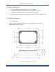
Mini Meter Installation Manual List of Figures Figure 1: Single Mini Meter and Epoxy Encapsulated Module......................................................... 3 Figure 2: Small Enclosure Outline and Mounting Dimensions......................................................... 4 Figure 3: Mini Meter Connections and Display................................................................................ 6 Figure 4: Mounting the Enclosure ……....................................................................
Mini Meter Installation Manual 1.3 Meter Certifications UL Recognized Component for us in US or Canada Conforms to accuracy requirements set forth in ANSI C12.10 Certified to California Division of Measurement Standards Approved by the California Energy Commission for use in California Solar 1.4 Physical Description 1.4.1 Single Meter Figure 1 below shows the dimensions of a single Mini Meter or Epoxy Encapsulated case and cover. Leviton Manufacturing Co., Inc.
Mini Meter Installation Manual 1.4.2 Enclosures Mini Meter and Epoxy Encapsulated module enclosures mounting drawings are shown below in figure 2. Leviton Manufacturing Co., Inc.
Mini Meter Installation Manual 2. Technical Specifications 2.1 Electrical Specifications Mini Meters and Epoxy Encapsulated Modules fall under UL Circuit Category III: a device for measurements performed in the building installation. The electrical specifications for Mini Meters are given in the table below. Input Configurations 1 Phase, 2 wire 1 or 2 Phase, 3 wire Supply Voltage Range (L1 or L2 to Neutral) Min. 102 VAC Max.
Mini Meter Installation Manual 2.2 Input/Output Connections and User Display Power LED Load LED Optional LCD Display area Sealing Studs Reverse Phase LED Figure 3: Mini Meter connections and display Voltage Inputs (wire connections) Description L1 Black wire, voltage input, Line 1, 120V with respect to neutral N White wire, Neutral input L2 Red wire, voltage input, Line 2, 120V with respect to neutral (7B and 5B models only) CT Inputs CT1 : X1 Current Transformer input, CT1.
Mini Meter Installation Manual Outputs 10, Isolated Output (10 Wh/P, Kh = 10) Isolated pulse output: 5 watthours on, 5 watthours off, referenced to ISOL COM NOT TO BE USED FOR FIELD WIRING 100, Isolated Output (100 Wh/P, Kh=100) Isolated pulse output: 50 watthours on, 50 watthours off, referenced to ISOL COM 1000, Isolated Output (1 kWh/P, Kh=1000) Isolated pulse output: 500 watthours on, 500 watthours off, referenced to ISOL COM (not available on models with T suffix) ISOL COM Isolated common for 1
Mini Meter Installation Manual 3. Installation Instructions The following section contains installation and wiring instructions for the Leviton Mini Meter™. If technical assistance is required at any point during the installation, contact information can be found at the end of this manual. Leviton is not responsible for damage to the meter caused by incorrect wiring. 3.1. Explanation of Warning Symbols Indicates the need to consult the operation manual due to the presence of a potential risk.
Mini Meter Installation Manual 3.3 Preparation 1. Verify the model number and electrical specifications of the device being installed to confirm they are appropriate for the intended electrical service (see Section 2). 2. Consult local codes for any possible permits or inspections required before beginning electrical work. 3. Ensure the conduit for the installation is flexible and non-metallic. For outdoor applications conduit and conduit fittings must be rated for UL Type 4x outdoor enclosures.
Mini Meter Installation Manual 3.5.2 Drilling Conduit Holes The bottom panel and lower half of the side panels work best for conduit opening locations in outdoor single meter enclosures. Select the location the makes wire installation easiest for the given environment. If the side panels are used, holes should be centered approximately half an inch from the bottom of the enclosure. Hole sizes must be appropriate to fittings, and large enough to fit all voltage and CT wiring (4-7 18 AWG min.
Mini Meter Installation Manual 3.6 Installation of Voltage Lines 1. Field wired voltage connections are made to the Mini Meter terminal block. The rated torque for these terminal blocks is 4.4 in-lb, and can be used with solid and stranded copper wires, at 12-18 AWG. 2. Verify that branch circuit fuse specifications meet local electric codes. 3. Connect 18 AWG min., 300 V min.
Mini Meter Installation Manual General Requirements: Splices on the CT leads must be within the meter enclosure, not inside the conduit. Leviton provided CT leads are 24 inches minimum. Wire insulation should be stripped so that the bare conductor length that connects to the meter terminal block does not exceed 0.300 inches. CTs should be securely fastened such that they will not slide down to live terminals.
Mini Meter Installation Manual Leviton Leviton 3-Phase, 4 wire hookup diagram Leviton Manufacturing Co., Inc.
Mini Meter Installation Manual 3.9 Testing the Installation Testing Voltage The power LED illuminates when the Mini Meter or Epoxy Encapsulated Module has a proper power supply. Voltage should also be tested using an AC Voltmeter to verify that the voltage across voltage line terminals (L1 to Neutral and L2 to Neutral) is not in excess of the maximum rated voltage. CT Reverse Phase Indicator Mini Meters and EE Modules have a red reverse phase indicator LED as described in section 2.3.
Mini Meter Installation Manual 4. Maintenance Properly installed meters with sound connections and secure conduit fittings should not require user maintenance. If the meter is functioning abnormally, consult the FAQ/Troubleshooting guide. If the answer cannot be found there, contact Leviton technical support. 5. Troubleshooting/FAQ Problem Solution 1. Power LED not illuminated 2. Load LED not flashing 3. Registered consumption low 4.
Mini Meter Installation Manual 6. Contact Information Leviton Manufacturing Co., Inc. Global Headquarters 201 N. Service Rd. Melville, NY 11747-3138 • Tech Line: 1-800-824-3005 • FAX: 1-800832-9538 Leviton Manufacturing Co., Inc. Lighting & Energy Solutions 20497 SW Teton Avenue, Tualatin, OR 97062 • Telephone: 1-800-736-6682 • FAX: 503-404-5594 Metering Tech Support: (6:00AM-4:00PM P.S.T. Monday-Friday): meters@leviton.com 1-800-959-6004 Leviton Manufacturing of Canada, Ltd.