
Instructions / Assembly

RENOIR II
2 WIRE FLUORESCENT DIMMING CONTROL
Cat. Nos. AWRMG-XXX, AWSMG-XXX & AWSMT-XXX
INSTALLATION
WARNINGS AND CAUTIONS:
• TO AVOID FIRE, SHOCK OR DEATH; TURN OFF POWER AT CIRCUIT BREAKER OR FUSE AND TEST THAT POWER IS OFF BEFORE WIRING!
• TO BE INSTALLED AND/OR USED IN ACCORDANCE WITH ELECTRICAL CODES AND REGULATIONS.
• IF YOU ARE NOT SURE ABOUT ANY PART OF THESE INSTRUCTIONS, CONSULT AN ELECTRICIAN.
• DO NOT GANG VERTICALLY.
• ONLY INSTALL FOR THE ALLOWED LOAD TYPES. INSTALLATION FOR ANY OTHER LOAD TYPE WILL VOID WARRANTY AND POSSIBLY CAUSE DAMAGE TO
THIS DEVICE AND/OR CONNECTED EQUIPMENT.
• USE THIS DEVICE WITH COPPER OR COPPER CLAD WIRE ONLY.
Installation Requirements:
• Thesedevicesaredesignedforinstallationintoametal2"x3"(5.08cmx7.62
cm)singlegangormulti-gangdevicebackbox.2-1/2"(6.35cm)ordeeper
backboxesarerequired.Thesedevicesarenotdesignedforamulti-gangeld
conguredbox.Insomeinstallationswhereconduitentryisfromtheside,or,in
multi-ganginstallationswherenipplesbetweentwoadjacentboxesareused,
deeperbackboxesmaybenecessary.Testtinstallationpriortorough-in.
• Installationofmultipledevicesintoasingleboxmayrequirede-ratingandother
specicinstallationprovisions.ReferenceMulti-Gang Installationsformore
details.
•
Asdevicesventtop/bottom,devicesshouldnotbeinstalledvertically
(oneovertheother).
• Toavoidickering,ashing,orlightsononedeviceadjustingwhenanother
device’slevelischanged,donotshareneutrals.Runseparateneutralsforeach
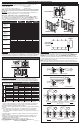
loadcircuitbacktothedevice.(See Figure 1).
Installation Instructions:
1. WARNING: TO AVOID FIRE, SHOCK OR DEATH; TURN OFF POWER AT
CIRCUIT BREAKER OR FUSE AND TEST THAT POWER IS OFF BEFORE
WIRING!
2.Removeexistingwallplateandswitch,ifapplicable.
3.Remove5/8"(1.6cm)ofinsulationfromeachcircuitconductor.Makesurethe
endsofwiresarestraight.
4.ConnectwiresperWIRINGDIAGRAMondeviceasfollows:Twiststrandsofeach
leadtightlytogetherand,withcircuitconductors,pushrmlyintoappropriatewire
connector.Screwconnectorsonclockwisemakingsurenobareconductorsshow
belowthewireconnectors.Secureeachconnectorwithelectricaltape.
5.Installationmaynowbecompletedbycarefullypositioningallwirestoprovide
roominoutletboxfordevice.Mountdeviceintoboxwithmountingscrews
supplied.Snapfaceplateintoplace.
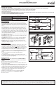
6.Installdevicecontrolpushbuttonandcontrolassembly(see Figure 2).
7.Restorepoweratcircuitbreakerorfuse.Installation is complete.
8.TestDeviceoperation.
INPUT - 120 - 277 VAC 60 HZ
OUTPUT-XA5A
OUTPUT-XB8.3A
OUTPUT-XC12.5A
OUTPUT-XD16A
Features and Operation:
• TurnDeviceONorOFF–PressingtheswitchwillturnthedeviceONifthe
deviceisOFF.IfthedeviceisON,pressingtheswitchwillturnthedeviceOFF.
• SetDeviceLevel–Adjusttheknoborslidertosetthedesiredoutputlevel.When
thedeviceturnsON,thedevicealwaysturnsONtothelevelsetbytheslideror
knob.
• SetCutoffLevel–Thecutofflevelisthelowestvoltagethedimmerwilloutput
beforeshuttingOFF.Tosetthecutofflevel,adjusttheknoborslidertothe
maximumoutput.Slowlylowertheoutputtothedesiredcutofflevel,thenpush
andholdthepowerbuttonfor5seconds.Thedimmerwilladjusttothenewlevel.
Toresetthecutofflevelto0,adjusttheknoborslidertotheminimumoutput,then
pushandholdthepowerbuttonfor5seconds.Ifyourloadisickering,notturning
ON,orsufferingfromanyothererraticbehaviorattheminimumsetting,raising
thecutofflevelmayeliminatetheproblem.
• PresetOperation–Whiledeviceisoff,setlevelofdevice.Thenpressbutton.The
devicewillturnonatthesetlevel.
• PowerRestore–Uponrestorationofpower,thedeviceturnsONtothestateit
wasinatthetimeofpowerloss.
• 5-WayOperation–Linktogether2,3,4,or5devicesformulti-waydimming.
• LEDLocator–AtthebottomoftheswitchisanLEDlocator.Thislocator
illuminateswhenthedeviceisOFFsoyoucanndthedeviceinthedark.
• RemoteControl–Ifyouareusingaremote,theoperationattheremoteis
identicaltotheoperationatthemaster.Aslightreactiondelaymaybenoticedif
operatinglevelchangesveryquickly.
ForTechnicalAssistanceCall:1-800-824-3005(U.S.A.Only)www.leviton.com
LIMITED 5 YEAR WARRANTY AND EXCLUSIONS
LevitonwarrantstotheoriginalconsumerpurchaserandnotforthebenetofanyoneelsethatthisproductatthetimeofitssalebyLevitonisfreeofdefectsinmaterialsandworkmanshipundernormalandproperuseforveyearsfromthepurchasedate.Leviton’sonlyobligation
istocorrectsuchdefectsbyrepairorreplacement,atitsoption,ifwithinsuchveyearperiodtheproductisreturnedprepaid,withproofofpurchasedate,andadescriptionoftheproblemtoLevitonManufacturingCo.,Inc.,Att:QualityAssuranceDepartment,201North
ServiceRoad,Melville,NewYork11747.Thiswarrantyexcludesandthereisdisclaimedliabilityforlaborforremovalofthisproductorreinstallation.Thiswarrantyisvoidifthisproductisinstalledimproperlyorinanimproperenvironment,overloaded,misused,opened,
abused,oralteredinanymanner,orisnotusedundernormaloperatingconditionsornotinaccordancewithanylabelsorinstructions.Therearenootherorimpliedwarrantiesofanykind,includingmerchantabilityandtnessforaparticularpurpose,butifanyimplied
warrantyisrequiredbytheapplicablejurisdiction,thedurationofanysuchimpliedwarranty,includingmerchantabilityandtnessforaparticularpurpose,islimitedtoveyears.Levitonisnotliableforincidental,indirect,special,orconsequentialdamages,including
withoutlimitation,damageto,orlossofuseof,anyequipment,lostsalesorprotsordelayorfailuretoperformthiswarrantyobligation.Theremediesprovidedhereinaretheexclusiveremediesunderthiswarranty,whetherbasedoncontract,tortorotherwise.
PK-93975-10-00-2A
Align flats when
installing knob
Center tab in opening
Figure2-RemoteDimmerAssembly
RotaryDevice SlideDevice
Wiring Diagram
Figure1-DONOTshareneutralwires
Blue
Hot (Black)
Neutral (White)
White
White
Load
Blue
Black
Black
White
Yellow
Yellow
Green
Ground
White
Hot (Black)
Neutral (White)
–
Load
X
–
Run a separate neutral wire
for each control circuit
–
Run a separate neutral wire
for each control circuit
DO NOT
share
neutral
wires
Green
Ground
Dimming Control
LOAD
Black
Blue
Neutral (White)
Hot (Black)
White
White Yellow
For use in multi-way
control (remote)
applications.
Cap wire if not used.
Ground (Green)
Line
120-277VAC
60 Hz