
Instructions / Assembly

1.Findthecellsthatcorrespondtoyourapplicationbyidentifyingtherowwiththe
numberofwideheatsinkdevicesyouhave,andthecolumnsthatcorrespondtothe
numberofnarrowheatsinkdevicesyouhave.Inthecellyou’llndthefollowing:
2.Thenumberindicatesthenumberof“Gangs”required.
3.Thelettersunderthenumberindicatetheorderdevicesshouldbeinstalled,N=narrow,
W=wide.
4.-W*=rightnbreak-offonwidedevice,N*=rightnbreak-offonnarrowdevice.
-*W=leftnbreak-offonwidedevice,*N=leftnbreak-offonnarrowdevice.
-*W*=nbreak-offonbothsidesofwidedevice,*N*=nbreak-offonbothsidesof
narrowdevice.
5.**indicatesthatuseofjumperbarsisrequired.Jumperbarscanbefoundinthekit
withthefaceplate.
6. Replace'x'inthefaceplatepartnumberwiththedesiredcolor:W=White,I=Ivory,
A=Almond,T=LightAlmond,E=Black,G=Gray,K=24KGold,L=SatinStainless,
R=AntiqueBronze,B=BrushedBrass.
NOTE:Metalnishesarenotavailableoncustomfaceplates.
BasicWIDE/NARROWcongurations,foradditionalcongurationssee:
www.leviton.com/RENOIRII
PK-93975-10-00-2A
©2012LevitonMfg.Co.,Inc.
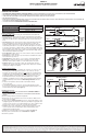
Multi-WayControl:
TheRenoirIIproductlinesupportsupto5-waycontrol.Anycombinationof
Dimmers,
FanControls,Switches,orRemotesaresupportedwithaMAXIMUM OF
5 DEVICES.TotalrunlengthfromendtoendisMAXIMUM 250 FEET.Remotes
requireUncontrolledHot,Neutral,&Groundforproperoperation.Onetravelerwireis
toruninbetweenallmastersandremotes.Remotesdraw15mApower(ea)fromthe
Controltowhichtheyareconnected.
NOTE:RemoteHot/NeutralshouldideallybefedfromthesamecircuitastheMaster.If
thisisnotpossible,ensurethatthemasterandremotearebothfedfromthesamephase.
MULTI-GANGINSTALLATIONREQUIREMENTS
Additional - Single Gang Box
Multi-WayControlWiringDiagram
Maximum 5 Devices, Dimmers, Remotes or Fan Controls
Maximum 250 feet
Device/Switch
Maximum 5 Devices, Dimmers, Remotes or Fan Controls
Maximum 250 feet
Remote
Device/Switch
Remote
Device/Switch
Remote
Device/Switch
Multiple Device/Switches and Remote Device/Switches
Master
Device/Switch
Remote
Device/Switch
Remote
Device/Switch
Remote
Device/Switch
Remote
Device/Switch
Hot
Neutral
Ground
Traveler
Hot
Neutral
Ground
Hot
Neutral
Ground
Traveler
Hot
Neutral
Ground
Traveler
Hot
Neutral
Ground
Traveler
Dimmed Hot
Neutral
Ground
LOAD
Hot
Neutral
Ground
Traveler
Hot
Neutral
Ground
Hot
Neutral
Ground
Traveler
Hot
Neutral
Ground
Traveler
Hot
Neutral
Ground
Traveler
Dimmed Hot
Neutral
Ground
LOAD
Dimmed Hot
Neutral
Ground
LOAD
Multiple Remote Device/Switches
Load in between Master Device/Switch and Remote Device/Switch
Master Device/Switch Remote Device/Switch
Dimmed Hot
Neutral
Ground
Hot
Neutral
Ground
Traveler
Hot
Neutral
Ground
LOAD
Load after Remote Device/Switch and Master Device/Switch
Master Device/SwitchRemote Device/Switch
Hot
Neutral
Ground
Hot
Neutral
Ground
Dimmed Hot
Neutral
Ground
Traveler
LOAD
Master
Device/Switch
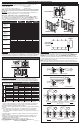
Figure 5 - Joiner Bar
Narrow/Narrow
Wide/Narrow Wide/Wide
Joiner Bar
Joiner Bar
3/4" space (use chase nipple)
3-1/2" deep
back box is
required
Four-gang wallbox Single-gang
wallbox
Fluorescent - 2 Wire Phase Control - 120-277VAC/VCA, 60HZ
Useonlyforcontrolofelectronicballastedluminaires.IntendedforAdvanceMark10,
LutronTu-Wire,orSylvaniaQuicktronicPowerSenseballasts.CAUTION:Toreduce
riskofoverheatingandpossibledamagetootherequipment,donotinstalltocontrola
receptacle,amotor-operatedappliance,oratransformersuppliedappliance.
Backbox - # Gangs
Wallplate Part #
Device Configuration
Backbox - # Gangs
Wallplate Part #
Device Configuration
Backbox - # Gangs
Wallplate Part #
Device Configuration
Backbox - # Gangs
Wallplate Part #
Device Configuration
Number & Type of NARROW
Number & Type of WIDE
0
1
2
3
0
4**
N+N+N
AWP00-30x
2
N*+*N
AWP00-20x
1
N
AWP0F-10x
1
6**
W+N+N+N
AWP00-31x
4
W+N*+*N
AWP00-21x
3
W+N
AWP0F-11x
1
W
AWP0F-01x
2
7
W+N*+N*+*N+W
AWP00-32x
6
W+N*+*N+W
AWP00-22x
5 or 6
W+N+W
AWP0F-12x
4
W+W
AWP0F-02x
3
9
W*+*W+N*+N*+*N+W
AWP00-33x
8
W*+*W+N*+*N+W
AWP00-23x
8
W+W+N+W
AWP0F-13x
6**
W+W+W
AWP0F-03x
Basic Configurations
Multi-Gang Installations:
Amulti-gangedinstallationexistswhenmultipledevicesareinstalledinthesame
backbox.Inmulti-ganginstallations,thefollowingmayberequired:
- Devicede-rating -Finremoval
- Useofjoinerbarsforadjacentdevices. - Backboxsize
NOTE: TEST FIT DEVICE INSTALLATION WITH THE WALL PLATE PRIOR TO BREAKING
FINS OR INSTALLING DEVICES TO ENSURE YOU UNDERSTAND ALL REQUIREMENTS.
BackBoxSize&JoinerBars:
Todeterminetherequiredback-boxsizeinmulti-ganginstallations,reference
tablebelow.Inapplicationswherethedevicesdonotlineupwithbackboxdevice
mountingholes,usejoinerbarstojointhecontrolstogether.ReferenceFigure 5.
De-ratings:
Whennsarebroken,somedevicesmustbede-rated.Referencetablebelowto
determinethedeviceratingswhen0,1,or2nsareremoved.
FinRemoval:
Whenitisdesiredtoinstalldevicesinassmallaspaceaspossible,allinsidensoflike
sized,adjacentdevicescanbebrokenoff.Figure 4showhowtobreakoffnsandthe
specicorderinwhichmultipledevicesmustbeinstalledinmulti-ganginstallations.
Figure4-FinRemoval
Back view of devices shown
Break off these fins
DO NOT Break off these fins
Break off these fins
Fin break off points
Fluorescent
2 Wire Phase Control
1500
12.5
3463
2875
1 fin
removed
600
5.0
1385
1150
780
6.5
1801
1495
1620
13.5
3740
3105
1224
10.2
2825
2346
840
7.0
1939
1610
1560
13.0
3601
2990
2 FINS
REMOVED
1476
12.3
3407
2829
636
5.3
1468
1219
1476
12.3
3407
2829
1044
8.7
2410
2001
1332
11.1
3075
2553
660
5.5
1524
1265
AWRMG-XA_
AWSMG-XA_
AWSMT-XA_
AWRMG-XB_
AWSMG-XB_
AWRMG-XC_
AWSMG-XC_
AWRMG-XD_
AWSMG-XD_
AWSMT-XB_
AWSMT-XC_
AWSMT-XD_
Amps
VA @ 120V
Amps
VA @ 120V
VA @ 230V
VA @ 277V
VA @ 230V
VA @ 277V
Amps
VA @ 120V
VA @ 230V
VA @ 277V
Amps
VA @ 120V
VA @ 230V
VA @ 277V
Amps
VA @ 120V
VA @ 230V
VA @ 277V
Amps
VA @ 120V
VA @ 230V
VA @ 277V
Amps
VA @ 120V
VA @ 230V
VA @ 277V
0 fins
removed
1000
8.3
2308
1917
1920
16.0
4432
3680
1500
12.5
3463
2875
1000
8.3
2308
1917
1920
16.0
4432
3680