User Guide 20/20 AD 20 Bit A/D Converter
Lexicon Precautions The 20/20 AD is a rugged device with extensive electronic protection. However, you should observe the same reasonable precautions that apply to any piece of audio equipment: • Always use the correct line voltage. • Do not install the 20/20 AD in a closed, unventilated rack, or directly above heat-producing equipment such as power amplifiers. • Never attach audio power amplifier outputs (speaker outputs) directly to any of the 20/20 AD's connectors.
20/20 AD User Guide SAFETY SUMMARY The following general safety precautions must be observed during all phases of operation, service and repair of this instrument. Failure to comply with these precautions, or with specific warnings elsewhere in these instructions violates safety standards of design manufacture and intended use of the instrument. Lexicon assumes no liability for the customer's failure to comply with these requirements.
20/20 AD User Guide Contents Introduction Controls and Connectors ...................................................................... 1 Unpacking • Power • Mounting .......................................................... 1 Front Panel Controls .......................................................................... 2 The Converter • The Level Meters • The Compressor Synchronization and Output Formatting • Alternate Modes Rear Panel Connectors ........................................................
20/20 AD User Guide Introduction The 20/20 AD is an analog-to-digital converter which can be configured for two 20-bit channels, or four 18-bit channels. Twin on-board signal processors provide 20-bit to 16-bit compression in the digital domain, as well as DC removal and a choice of four dither types. The compressor allows leeway in setting levels and provides insurance against clipping in the digital domain.
Controls and Connectors 20/20 AD User Guide After unpacking the 20/20 AD, save all packing materials in case you ever need to ship the unit. Thoroughly inspect the 20/20 AD and packing materials for signs of damage. Report any shipment damage to the carrier at once. The following accessories are included with the 20/20 AD: Controls and Connectors Unpacking 1. Power Cable 2. User Guide 3. Quick Reference Guide The 20/20 AD is equipped with a 3-pin IEC connector and detachable line cord.
Controls and Connectors Lexicon 20/20 AD Front Panel Controls The 20/20 AD front panel controls are divided into three functional groups for conversion, compression, and synchronization/output formatting.
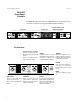
20/20 AD User Guide Controls and Connectors The Level Meters When the compressor is off, the behavior of the level meters is determined by the settings of the 1dB SCALE, and PK HOLD switches. When the compressor is on, pressing DISPLAY will cause gain reduction (in dB) to be displayed on the two right hand meters (2-channel mode) or on all four meters (4-channel mode). The following charts show all of the possible states of the level meter and the value in decibels for each state.
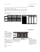
Controls and Connectors Lexicon Synchronization and Output Formatting DITHER Selects the type of dither: wide bandwidth, 20 bit, or High Frequency . DITHER FORMAT FORMAT Selects the format to be available at the output connectors, AES or S/PDIF. Note: The format selected here will be sent to all outputs. AES / WC: WIDE HF 48 AES WC PRES 20 BIT PL DN 44.1 SPDIF AES LOCK AES/WC In internal sync mode, PRES indicates that either WC or AES is available at the inputs as a sync source.
20/20 AD User Guide Controls and Connectors 20/20 AD Rear Panel Connectors BAL/UNBAL Push on/push off switch. Set button to correspond to input signal type. A mismatch between the input signal and the setting of this switch, will be indicated on the front panel by the BAL LED. Analog Input 3-pin XLR connectors. In 2channel mode, only inputs 1 and 2 are active. AC Power Standard 3-pin IEC power connector.
Controls and Connectors Lexicon Audio Connections Connectors Signal Mating Connector Description AES/EBU Digital Input XLR A3M Balanced RS-422 AES/EBU Digital Output XLR A3F Balanced RS-422 S/PDIF Consumer Digital Output RCA Unbalanced 75Ω S/PDIF Consumer Digital Audio Optical Output Consumer Digital Word Clock BNC Unbalanced 75Ω Analog Input XLR pin 2 high XLR Pinout Male 2 = high 3 = low 1 = ground Female 1 = ground 3 = low 2 = high XLR Pinout — pin 2 high by convention 6
20/20 AD User Guide Controls and Connectors Cables This interface requires balanced connections using high-quality, low-capacitance, controlled-impedance, data communication, twisted-shielded pair cable. Microphone cable may introduce a significant amount of jitter into the signal, causing distortion. AES/EBU Digital Output Use commercially-available, consumer audio optical cable assemblies.
20/20 AD User Guide the 20/20 AD Using theUsing 20-/20 AD The 20/20 AD has four analog inputs: CH1, CH2, CH3 and CH4. In two-channel mode, only CH1 and CH2 are used, and the dynamic range of the unit is extended. If you have two stereo pairs, one of which is used more often than the other, the most often used pair should be assigned to CH1 and CH2, and the other pair to CH3 and CH4. This allows you to take advantage of the extended dynamic range of two-channel mode when using only a single stereo pair.
Using the 20/20 AD Lexicon CAUTION These instructions are for use by qualified personnel only. Before opening the 20/20 AD, REMOVE THE POWER CORD. You may be exposed to hazardous voltages even if power to the unit is turned off. WARNING Turn off power and REMOVE THE POWER CORD before opening the unit. Take a moment to study the figure below. This diagram shows the terminating and grounding of input signals for the unit, and explains the function of most of the jumpers on the 20/20 AD Main pc board.
20/20 AD User Guide Using the 20/20 AD The following figure indicates the locations and factory settings of these jumpers on the board. In their closed positions, the jumpers have their right two (or lower two) pins shunted together. To open a jumper, move the shunting block to the left (or upper) two pins. (Note that the jumpers in J13 have only two pins; to open, simply remove the shunting block.
Using the 20/20 AD Lexicon Balanced and Make sure the BALANCE switches located on the rear panel are set to match Unbalanced the type of input. (OUT=balanced , IN=unbalanced). The red UNBAL lights on Input Signals the front panel will indicate an error if there is a mismatch between the switch setting and the signal type. Note that when an UNBAL light goes on, there is a good chance that the input signal has been audibly clipped, even if the level meter does not indicate an overload.
20/20 AD User Guide Adjust the front panel Gain knobs until the peak input levels are balanced and come within a few dB of clipping. For now, make sure that the DISPLAY switch in the DIGITAL COMP/LIMITER section is set to OFF. In normal operation, each level meter will indicate the level at the output of the converter in dB referenced to digital full scale (dBfs). A lighted green or yellow LED indicates that the signal has exceeded the level printed next to it.
Using the 20/20 AD Lexicon Synchronization The 20/20 AD can synchronize to its internally derived sample clock at 44.1kHz and Sample Rate or 48kHz, or to an external AES or Word Clock signal, in the range of 41-51kHz. The EXT SYNC switch allows you to select external Word Clock (WC), external AES (AES), or internal source (WC and AES off). Before switching between Internal and External modes, be sure to reduce monitor volume as some D/A converters do not mute when they lose lock.
20/20 AD User Guide Using the 20/20 AD The 20/20 AD is shipped configured for Internal mode. To operate in External mode, press EXT SYNC until the desired sync source (WC or AES) lights. If the selected sync source light flashes and the PRES light is not on, it indicates that there is no signal present as a sync source. If the selected sync source and PRES lights are on, but the LOCK light is off, the selected sync source is present, but is not within the 41-51kHz lock range.
Using the 20/20 AD Lexicon About Dither Dither is a low-level pseudo-random signal which is added to digital audio to reduce quantization noise, in effect, by replacing it with a “nicer sounding” noise. If the recorder or workstation which follows the 20/20 AD is capable of recording or processing 20 bits, the DITHER switch should be set to 20 BIT. If, however, the equipment can only record or process a 16-bit signal, either WIDE or HF dither should be selected.
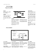
20/20 AD User Guide Using the 20/20 AD -60.00 -60.00 -70.00 -70.00 -80.00 -80.00 -90.00 -90.00 -100.0 -100.0 -110.0 -110.0 -120.0 -120.0 -130.0 -130.0 -140.0 -140.0 -150.0 -150.0 -160.0 -160.0 0.0 2.00k 4.00k 6.00k 8.00k 10.0k 12.0k 14.0k 16.0k 18.0k 0.0 20.0k Plot of noise + distortion vs. frequency for the 20/20 AD in 2channel mode with a -60dBfs sinewave at 1kHz. 2.00k 4.00k 6.00k 8.00k 10.0k 12.0k 14.0k 16.0k 18.0k 20.
Using the 20/20 AD Lexicon Automatic Offset DC offsets are created by input amplifiers and A/D converters for a number of Removal reasons. In the 20/20 AD, these typically include temperature changes, changes between 2-channel and 4-channel mode, change of sample rate or sync source, or large adjustments of input level controls. The DSP chips in the 20/20 AD automatically remove these DC offsets by passing data from the converters through a digital high pass filter with a corner frequency of less than 0.
20/20 AD User Guide Using the 20/20 AD Note that the 6dB GAIN setting is given only as an example. Feel free to experiment with any level in this mode. (GAIN settings above 12dB are not available because at that point practically all of the dynamic range of the converter will fit onto 16-bit media. ) Set THRESHOLD to -24dB. Now, when the signal level exceeds -24dB, the gain is gradually reduced until, at 0dB signal level, the compression gain is also at 0dB (unity).
Using the 20/20 AD Lexicon THRESHOLD GAIN 0dB 1 2 3 4 5 6 7 8 9 10 11 12 -3dB 1.50:1 3.00:1 4.00:1 4.00:1 4.00:1 4.00:1 4.00:1 4.00:1 4.00:1 4.00:1 4.00:1 4.00:1 -6dB 1.20:1 1.50:1 2.00:1 3.00:1 4.00:1 4.00:1 4.00:1 4.00:1 4.00:1 4.00:1 4.00:1 4.00:1 -8dB 1.14:1 1.33:1 1.66:1 2.00:1 2.66:1 4.00:1 4.00:1 4.00:1 4.00:1 4.00:1 4.00:1 4.00:1 -10dB 1.11:1 1.25:1 1.42:1 1.66:1 2.00:1 2.50:1 3.33:1 4.00:1 4.00:1 4.00:1 4.00:1 4.00:1 -12dB 1.
20/20 AD User Guide When RELEASE is set to 0, the compressor acts like an amplifier with a nonlinear transfer function. For example, setting GAIN to 6dB and THRESHOLD to -14dB produces a close approximation of a generic tape saturation curve. This mode is also useful for overload protection of some types of percussive instruments. Using the 20/20 AD Non-linear Transfer Functions Note: This function is not available in 4-channel mode.
Using the 20/20 AD Lexicon To summarize: 1. Set the input levels so that the peak level is a few dB below clipping. 2. Turn on the compressor. 3. Set compressor GAIN to the input level safety margin, and THRESHOLD to 0dB. 4. Adjust RELEASE to suit the program material. The faster the expected clipping source, the faster the release time should be. 5. Adjust THRESHOLD to suit the program material.
20/20 AD User Guide In 2-channel mode, when the LINK switch is off, each of the two channels is compressed independently. When the LINK switch is on, the louder of the two channels sets the amount of compression. This serves the same function as “stereo link” in analog compressors. When you are recording a stereo signal and want to maintain the stereo image, LINK should be on.
Using the 20/20 AD Lexicon Realigning Two DAT When recording in 4-channel mode to two DAT recorders, it may be useful to Recordings record a "clapper" signal to both DATs to facilitate realignment during postproduction. When you press ALT-LINK, the 20/20 AD will generate 8mS of silence, followed by an 8-cycle 1 kHz square wave burst at -12dBfs This signal is time-aligned on all four output channels.
20/20 AD User Guide Definition of Terms Definition of Terms AES : Audio Engineering Society. aliasing : a form of distortion which occurs when an A/D converter’s sample rate is less than twice the highest frequency component of a signal. frequency : the number of vibrations per unit of time, expressed in cycles per second (Hz). harmonic distortion : the appearance of harmonics of the input signal at the output of a device.
20/20 AD User Guide Definition of Terms Definition of Terms AES : Audio Engineering Society. aliasing : a form of distortion which occurs when an A/D converter’s sample rate is less than twice the highest frequency component of a signal. frequency : the number of vibrations per unit of time, expressed in cycles per second (Hz). harmonic distortion : the appearance of harmonics of the input signal at the output of a device.
3 Oak Park Bedford, MA 01730 USA Tel: 781-280-0300 Fax: 781-280-0499