Owner's Manual MC-1 Digital Controller
Important Safety Instructions Save these instructions for later use. Follow all instructions and warnings marked on the unit. Always use with the correct line voltage. Refer to the manufacturer's operating instructions for power requirements. Be advised that different operating voltages may require the use of a different line cord and/or attachment plug. Do not install the unit in an unventilated rack, or directly above heat producing equipment such as power amplifiers.
Dansk Vigtig information om sikkerhed Suomi Tärkeitä turvallisuusohjeita Gem denne vejledning til senere brug. Säilytä nämä ohjeet tulevaa käyttöä varten. Følg alle anvisninger og advarsler på apparatet. Seuraa kaikkia yksikköön merkittyjä ohjeita ja varoituksia. Apparatet skal altid tilsluttes den korrekte spænding. Der henvises til brugsanvisningen, der indeholder specifikationer for strømforsyning.
Deutsch Wichtige Sicherheitsanweisungen Español Instrucciones importantes de seguridad Heben Sie sich diese Sicherheitsanweisungen auch für später auf. Befolgen Sie alle auf der Vorrichtung stehenden Anweisungen und Warnungen. Immer nur mit der richtigen Spannung verwenden! Die Gebrauchsanweisungen des Herstellers informieren Sie über die elektrischen Anforderungen. Vergessen Sie nicht daß bei verschiedenen Betriebsspannungen ggf.
Contents Introduction 1 Installation Controls and Indicators ..................................................... 1 The Front Panel ................................................................ 1 The Rear Panel ................................................................. 2 The Remote Control .......................................................... 3 Alternate Remote Control Functions Using the Shift and Record/Zone 2 buttons Connection .............................................................
Introduction The MC-1 can be thought of as four units in one. At its heart is a reference-quality 8-channel music and film digital audio computer capable of creating or recreating a limitless amount of listening environments. This digital audio computer is mated to an 8-channel, 24-bit Digital-to-Analog converter that rivals the most exotic and costly standalone devices.
Lexicon soundtracks as well as Surround EX for those recorded in the Dolby Digital and DTS discrete formats. These enhancements ensure that film soundtracks, which are typically mixed for the acoustics of large theaters, sound as the filmmakers intended when played back in the relatively small environment of a home theater. Using the Documentation Because the MC-1 is designed to be customized for your system and your listening space, the information required for installation is extensive.
Effect An effect is a configuration that determines how the MC-1 will process an input signal. The MC-1 contains 24 effects: Panorama, Nightclub, Concert Hall, Church, Cathedral, Party, 2-Channel, Music Surround, Music Logic, Logic 7, TV Matrix, Pro Logic, THX Cinema, Mono Logic, 5.1 2-Channel, 5.1 Music, 5.1 Logic 7, Dolby Digital, THX 5.1, DTS 2-Channel, DTS Music, DTS Logic 7, DTS Film and DTS THX 5.1. Parameter Each Effect has a set of parameters (controls) that characterize it.
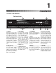
1 Installation MC-1 Digital Controller Installation Controls and Indicators The Front Panel 7 9 8 MC-1 Digital Controller LEXICON MC-1 COPYRIGHT 1999 Power VCR 1 1. POWER Alternately puts the MC-1 into and out of standby. Turning the MC-1 off with this button (or with the remote) deactivates the unit while leaving power to the signal processing circuitry to keep it at optimum operating temperature. Turning the MC-1 on with this button (or the remote) will restore the previous operating state. 2.
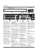
Installation Lexicon 4 The Rear Panel CAUTION: Never make or break any connections to the MC-1 with the rear-panel power ON. Make sure any associated amplifiers are turned off before turning this master power switch on or off. TRIGGERS TRIGGERS IR IN PGM GND PWR 5 6 S/PDIF INTPUTS VIDEO TUNER L CD AUX TV L R V-DISC DVD VCR 11 1 CAUTION 2 3 A B EXPANSION PORTS 4 1 1 AUDIO INPUTS 8 stereo analog audio inputs switched with corresponding video inputs and fed to the Monitor outputs.
Installation MC-1 Digital Controller The Remote Control 1 ON, FP and OSD ON turns the MC-1 on and selects the input last used with main and Zone 2 volume levels set to the levels chosen in the OUTPUT LEVELS menu. FP (ON) turns on the front panel display. OSD (ON) activates the MC1 on-screen display. 2 OSD 3 FP FP OSD Shift Record DONE 4 SELECT 7 5 Zone 2 6 2 OFF, FP and OSD OFF puts the unit into standby and mutes all of the outputs.
Installation Lexicon Alternate Remote Control Functions Using the Shift and Record/Zone 2 buttons You can access an additional set of controls with the MC-1 remote control by using the Shift key. PGM trigger OFF OFF Menu background OFF OSD L/R Balance adjust Press and hold with buttons shown to access these remote control functions Center balance and fader Loudness OFF, Bass, Treble and Tilt to +0.
Installation MC-1 Digital Controller Zone 2 controls are accessed by holding down the Record/Zone 2 button.
Installation Lexicon Connection Location Considerations The MC-1 is a highly specialized signal processing computer and requires special care during installation to ensure optimum performance. The MC-1 may be installed on a shelf or in a standard 19" equipment rack, using an optional rack-mount kit available from Lexicon dealers. Observe the following precautions: • • • • Select a dry, well-ventilated location out of direct sunlight.
Installation MC-1 Digital Controller Wiring Considerations Audio/Video Cables There is debate over the audible effects of different types of interconnects. Good engineering practices have minimized the effect that cables might have on the inputs and outputs of the MC-1 — but feel free to evaluate different interconnects in your system. Be conscious, however, of the mechanical stress from repeated insertion and overly tight connectors, and the possibly corrosive nature of some contactenhancing fluids.
Installation Lexicon AC-3 RF Optical or Coax Digital VIDEO DISC PLAYER ZONE 2 AMPLIFIER and SPEAKERS LDD-1 In Out VIDEO MONITOR or PROCESOR to Lexicon Amplifiers S/PDIF INTPUTS VIDEO S/PDIF OUT TAPE TUNER CD AUDIO AUDIO AUX TV L L R R V-DISC DVD VCR RECORD 1 RECORD 2 L R CAUTION 2 3 4 A B EXPANSION PORTS RS 232 ATTENTION RISQUE DE CHOC ELECTRIQUE NE PAS OUVRIR 5 1 R REAR 2 3 SIDE CENTER FRONT C LISTED AUDIO EQUIPMENT 7D77 E172268 LEXICON, INC. ASSEMBLED IN U.S.A.
Installation MC-1 Digital Controller Video Connections The MC-1 has eight composite and S-Video inputs. Connection to an SVideo input will override the composite signal connected via the RCAtype connector. Note that an S-Video input will be output on both the composite and S-Video outputs. Composite input signals will not be output as S-Video. You can assign any video source to any (or all) of the eight MC-1 inputs via the Input Configuration submenu of the Setup menu.
Installation Lexicon NOTE: Whenever playback of a 24/96 disc is desired, press 2-CH while holding down the Shift button on the remote control. If you are using SMALL loudspeakers, these inputs will send a full frequency response signal to the outputs, completely bypassing the internal crossovers. Do not use this input with Dolby Digital or DTS signals. Whenever playback of non-24/96 discs is desired, select the regular input on the MC-1 remote control or front panel.
2 System Configuration MC-1 Digital Controller System Configuration Restore Factory Defaults Although the MC-1 memory is cleared before it leaves the factory, it is good practice to restore the factory defaults with the following procedure before system configuration. Turn the MC-1 OFF with the remote control. Turn the unit back ON and immediately press and hold the MUTE button on the remote. (Make sure you do not block the infrared receiver on the MC-1 front panel.
System Configuration Lexicon (dB) (dB) 9.0000 9.0000 7.0000 7.0000 5.0000 5.0000 3.0000 3.0000 1.0000 1.0000 -1.000 -1.000 -3.000 -3.000 -5.000 -5.000 -7.000 -7.000 -9.000 -9.000 20 100 1k 10k 20k (Hz) Bass Tone Control Frequency Response 20 100 1k 10k 20k (Hz) Treble Tone Control Frequency Response Tilt The Tilt parameter can be thought of as a straight line that pivots on a fulcrum at 1kHz to correct the overall tonal balance of source material. The range is -3.0dB to +3.
System Configuration MC-1 Digital Controller Display Adjustment MAIN MENU EFFECT ADJUST EQUALIZATION DISPLAY ADJUST SETUP Depending on the location of the MC-1 in your room, you may need to adjust the brightness of the front panel display for optimum viewing. To adjust this display, press the ▲, ▼ or SELECT buttons on the Remote to enter the Main Menu. Press ▼ twice to select DISPLAY ADJUST. Press SELECT to highlight the Display Adjust Menu. Press ▼ to select FRONT PANEL DISPLAY.
System Configuration Lexicon DISPLAY ADJUST MENU ON-SCREEN DISPLAY FRONT PANEL DISPLAY ON-SCREEN DISPLAY STATUS 2 SECONDS TOP POSITION NTSC FORMAT ENABLE COLOR MENU BACKGROUND ON Adjust with ▲ or ▼ ALWAYS ON, 2 SECONDS, ALWAYS OFF TOP, CENTER, BOTTOM NTSC, PAL, SECAM ENABLE, DISABLE ON, OFF This menu allows you to choose the position and duration of items displayed on-screen during normal operation, as well as the options of color or black and white display and conformance to local video format.
System Configuration MC-1 Digital Controller Input Configuration SETUP MENU INPUT CONFIG SPEAKER CONFIG OUTPUT LEVELS LISTENER POSITION INPUT LOCK SETTINGS CONFIG MENU VCR DVD V-DISC TV AUX CD TUNER TAPE The MC-1 has eight inputs, each of which can be associated with any of the eight video and eight digital audio inputs. Selecting Input Configuration from the Setup menu displays a sub-menu which lists these inputs and allows you to select them individually for adjustment.
System Configuration Lexicon Input Level Meters INPUT GAIN CD AUTO MANUAL ON +00dB AUTO GAIN: L +00dB R PEAK LEVEL: When GAIN is selected, two on-screen horizontal bar meters display peak incoming signal level. The highest peak level is shown in dB in a separate text line, and as an arrow in the the meter display. White, yellow and red sections of the bar meter show increasing levels. The white portion is shown in 3dB increments, the yellow and red portions are shown in 1.5dB increments.
System Configuration MC-1 Digital Controller The MC-1 can also be set up to automatically switch to an appropriate effect whenever PCM, AC-3 or DTS encoded material is detected at the input. This allows one input to be used for different formats. For example, in the factory default state, the V-DISC input will automatically load the appropriate version of Logic 7 when an AC-3, DTS, or PCM signal is present. The default selections for input effect assignment are shown below.
System Configuration Lexicon The MC-1 V-DISC input is selected. A movie encoded in Dolby Surround is put in the laser disc player and starts to play. The LDD-1 recognizes that the movie is not AC-3 encoded, and automatically routes the laser disc player's PCM (2-channel digital) signal to the MC-1. The MC-1 identifies the signal as PCM and automatically loads the LOGIC 7 effect (as specified in the INPUT CONFIG menu). Now, assume the movie is replaced with one that is encoded in Dolby Digital (AC-3).
System Configuration MC-1 Digital Controller PCM Only NOTE: PCM ONLY is automatically selected for an input whenever ANALOG is selected as the AUDIO IN setting, as AC-3 and DTS effects are incompatible with analog inputs. If PCM ONLY is selected as the FX FORMAT for a given input, only PCM effects in the MC-1 can be used. When the MC-1 receives a signal which is not PCM encoded, it will mute and display "NO PCM AUDIO.
System Configuration Lexicon Audio In This option in the INPUT CONFIG menu determines which audio input connector on the MC-1 rear panel will be used for the MAIN zone. Using the digital inputs will always yield better performance, and these should be used whenever a source component has a digital audio output. The options available for AUDIO IN are: ANALOG, COAX (1-5) and OPTICAL (1-3).
System Configuration MC-1 Digital Controller Record/Zone 2 The MC-1 is designed to be the control center of any system. As such, there are separate outputs for easy integration of external recording devices as well as an additional “zone” in multi-room installations. The Record and Zone 2 outputs on the MC-1 are wired in parallel so that the input selection will always be the same for both. For example, if the CD input is selected for Record, the CD input is also output to Zone 2.
System Configuration Lexicon LED and redirects the current main zone input to the Record/Zone 2 outputs. From Standby, turns the unit on, selects the last used Zone 2 input, turns Zone 2 volume on to the value selected in the OUTPUT LEVELS menu and engages full mute in the main zone. OFF Turns off the Zone 2 outputs, and the associated front panel LEDs. OSD (ON) Displays a STATUS menu for the current input. Press Done to exit. VOL ▲ and ▼ Displays, then adjusts the current Zone 2 volume level.
System Configuration MC-1 Digital Controller PGM Trigger Assignment TRIGGERS TRIGGERS IR IN PGM GND PWR GND PWR PGM This menu item assigns the status for the programmable (PGM) trigger on the MC-1 rear panel. +12VDC is provided for controlling ancillary equipment or functions. Selections are ENABLE or DISABLE for the selected input. The factory default is ENABLE (high) for A/V inputs and DISABLE (low) for audio only inputs. (+5VDC is available via internal jumper.
System Configuration Lexicon Center dBr 0.0 -1.000 -2.000 -3.000 -4.000 -5.000 -6.000 -7.000 -8.000 -9.000 -10.00 -11.00 -12.00 -13.00 -14.00 -15.00 -16.00 -17.00 -18.00 10 20 50 100 200 500 1k 2k 5k 10k Systems that utilize a full-range center speaker should select LARGE to direct center information to the center output with a full frequency response. Select SMALL for installations where the center speaker is smaller than the left and right front speakers.
System Configuration MC-1 Digital Controller Subwoofer Output dBr Use of the subwoofer output is specified here. Selecting YES, then pressing SELECT allows you to display and adjust the crossover frequency for the subwoofer output. All summing and filtering is performed in the digital domain. You can select three different crossover points (40, 80 or 120Hz) for the subwoofer.
System Configuration Lexicon Select INTERNAL NOISE TEST or EXTERNAL NOISE TEST from the Output Levels menu. The INTERNAL NOISE TEST disables any EQ functions, centers the Balance and Fader controls, and sets the system volume to +00dB. The test signal circles the room according to the speaker configuration you have defined in the Speaker Configuration menu. For a full complement of speakers, the order is: Left Front, Center, Right Front, Right Side, Left Side, Subwoofer, Right Rear, Left Rear.
System Configuration MC-1 Digital Controller Note that the Volume control is active when utilizing external noise calibration. a Dolby Digital AC-3 signal is coming in, the MC-1 will load the DOLBY DIGITAL effect with the factory preset settings. If a DTS signal is coming in, the MC-1 will load the DTS FILM effect with the factory preset settings.
System Configuration Lexicon Be sure the limiter is set to ON before exiting. Press DONE to exit and automatically set the limiter to the level you have selected. Mute Level This menu allows you to set the level of attenuation used whenever the MC-1 MUTE function is engaged. In the Output Levels menu, attenuation levels of -10dB, -20dB, -30dB, -40dB, and FULL are available. Power On Volume This control in the Output Levels menu allows you to select the volume at which the MC-1 will power on.
System Configuration MC-1 Digital Controller Once you have entered the distance to the nearest speaker, the MC-1 will automatically calculate the maximum allowable distance. The display will show all of the speakers, each with a default distance setting equal to your nearest speaker. Use SELECT and ▲ and ▼ to highlight and enter actual distances for each speaker. The MC-1 rounds off distance settings into discrete steps – choose the closest step to the actual distance in these cases.
System Configuration Lexicon LISTENER POSITION 60° L127 . . . Center . . . R127 SPEAKER ANGLE is the angle between the main speakers as seen from the listening position — here it is about 60 °. LISTENER POS allows you to adjust for an offset listening position. SILENCE { NOISE Move your head from side to side to find the position where the noise is full left, and the right ear hears near total silence.
MC-1 Digital Controller System Configuration L/R Balance This control allows you to adjust the left/right balance of the front, side and rear main outputs. This control can also be accessed on the remote by pressing and holding the Shift button and using DONE to move to the left, and SELECT to move to the right. Zone 2 Balance This control allows you to adjust the left/right balance of the Zone 2 outputs.
System Configuration Lexicon Customization After you have calibrated and customized the MC-1, there are two additional steps recommended to safeguard the settings. First, document your adjustments using the worksheet at the end of this manual. Second, consider locking the settings so that they cannot be inadvertently changed. The last item in the Setup menu allows you to lock the MC-1 settings, as well as to change the name displayed during power up.
System Configuration MC-1 Digital Controller Using MC-1 Effects MAIN MENU EFFECT ADJUST EQUALIZATION DISPLAY ADJUST SETUP When EFFECT ADJUST is selected from the Main menu, the on-screen display shows a list of parameters specific to the current effect, as well as the current value of each parameter. (The front panel display shows one parameter at a time). Use the ▲ and ▼ buttons to move through the displayed list.
System Configuration Lexicon Restoring the original parameter values of an Effect The RESTORE PARAMETERS function allows you restore the currently selected Effect to its factory preset state. When you select this function, you will be prompted to reconsider erasing your changes. — If you don’t want to erase your versions, press DONE to exit the menu. Pressing SELECT in response to the displayed query will restore all of the factory preset values to the Effect.
3 PCM Effects and Parameters MC-1 Digital Controller PCM Effects and Parameters The PCM Effects are compatible with two-channel input signals (analog or digital). Panorama Panorama extracts the natural ambience from recorded music and moves it outward from the speakers, producing greater width and depth of image and a feeling of enhanced spaciousness. This mode adds no additional sound but expands the existing stereo image.
PCM Effects and Parameters Lexicon Concert Hall The Concert Hall Effect generates the appropriate early reflections for simulation of many different halls, and sends the reflections to all channels in addition to the direct signal in the main speaker. This Effect is not appropriate for highly percussive music. Parameter CENTER LEVEL SPEECH DETECT HALL SIZE LIVENESS ROLLOFF SUBWOOFER LVL EFFECT LEVEL CUSTOM Initial Value Range 8 ON 30 Meters 4 3.3kHz +00dB -01dB 0-15 ON/OFF 20-30 Meters 0-6 453Hz-20.
PCM Effects and Parameters MC-1 Digital Controller Party The Party effect allows unprocessed stereo signals to be played over all speakers for background music or for maximum acoustical output of the system. Parameter CENTER LEVEL SIDE LEVEL REAR LEVEL SUBWOOFER LVL CUSTOM Initial Value Range 15 +00dB +00dB +00dB 0-15 OFF, -30dB to +05dB OFF, -30dB to +05dB OFF, -30dB to +05dB 2-Channel The 2- Channel effect allows you to use your system for traditional two channel playback.
PCM Effects and Parameters Lexicon Music Logic Music Logic is a surround effect developed specifically for music listening. It makes full use of additional loudspeakers placed at the center, sides and rear of the room and provides a slight amount of steering for the front channels. Parameter CENTER LEVEL VOCAL ENHANCE FRONT STEERING SOUNDSTAGE 5 SPEAKER ENHANCE BASS ENHANCE SURROUND ROLLOFF REAR DELAY OFFSET SIDE LEVEL REAR LEVEL SUBWOOFER LVL CUSTOM Initial Value Range 16 +3.
PCM Effects and Parameters MC-1 Digital Controller TV Matrix The TV Matrix effect provides surround effects for television viewing of monaural, stereo, and stereo synthesized programs. Parameter AUTO AZIMUTH VOCAL ENHANCE FRONT STEERING RE-EQUALIZER SOUNDSTAGE 5 SPEAKER ENHANCE BASS ENHANCE SURROUND ROLLOFF SIDE LEVEL REAR LEVEL SUBWOOFER LVL CUSTOM Initial Value Range ON +3.0dB MUSIC OFF REAR ON OFF 6.9kHz +00dB +00dB +00dB ON/OFF 0.0dB, +3.0dB, +6.
PCM Effects and Parameters Lexicon Mono Logic Mono Logic takes a monaural soundtrack and sends music and sound effects to the sides and rear through a room simulator mode while keeping the dialog in the center. Parameter MAIN LEVEL ACADEMY FILTER ROLLOFF SUBWOOFER LVL EFFECT LEVEL CUSTOM Initial Value Range 8 ON 3.3kHz +00dB -04dB 0-16 ON/OFF 453Hz to 20.
MC-1 Digital Controller PCM Effects and Parameters speakers are used for bass enhancement, the effectiveness is improved with speakers capable of reproducing reproducing low frequencies (LARGE). Using speakers that are not capable of producing low frequencies (<80Hz) may cause damage to them. BASS RT (low frequency reverberation time) depends on MID RT and is expressed as a multiplier. BASS RT should be set to 1.0 x MID RT for a more natural effect in smaller spaces.
PCM Effects and Parameters Lexicon LOW FREQ WIDTH allows you to apply low-frequency spatial correction to the signal. Positive values of LOW FREQ Width indicate that the difference signal (L-R) has additional energy below 500Hz, while the sum (L+R) has correspondingly less. Negative settings of LOW FREQ WIDTH can compensate for recordings with too much of this property. This control can add needed spaciousness and warmth to classical recordings made with coincident or near-coincident microphones.
MC-1 Digital Controller PCM Effects and Parameters ROLLOFF mimics the absorption of the air in the hall and, typically, should begin with a low frequency to simulate large spaces. SIDE LEVEL controls the volume level of the side speakers. Although we have selected a default value, the correct setting will vary with each recording, the room, and your personal taste. SIDE ROLLOFF provides a high frequency cutoff for the side speakers.
PCM Effects and Parameters Lexicon SURROUND ROLLOFF allows the high frequencies of the surround channels to be attenuated with the same detection circuitry as that described for the Soundstage control. The attenuation is quite attractive on many music and broadcast sources which were not mixed for surround. When a surround source is detected, these filters are removed, so the rear speakers can reproduce surround events with full bandwidth.
MC-1 Digital Controller 4 AC-3 Effects and Parameters AC-3 Effects and Parameters AC-3 Effects are compatible with Dolby Digital input signals. Any AC-3capable software and/or source components should be labeled with a badge, similar to the one on the MC-1 front panel. AC-3 Status Display AC-3 STATUS MATRIX ENCODED NO DOWNMIX NO SAMPLE RATE 48kHz DATA RATE 384 kb/sec PGM CONTENT 3/2.
AC-3 Effects and Parameters Lexicon 5.1 2-Channel This Effect mixes Dolby Digital 5.1 information for two-channel playback. These soundtracks can be recorded onto two-channel formats, or played back through left and right front speakers. The mix is designed to play back with full surround when decoded through Logic 7. In mixing a film with very heavy use of the Low Frequency Effects Channel, it may be desirable to lower LFE MIX LEVEL.
AC-3 Effects and Parameters MC-1 Digital Controller 5.1 Logic 7 5.1 Logic 7 combines all the features of Dolby Digital AC-3 with enhancements by Lexicon and LucasFilm. This effect uses Logic 7 matrix technology to enhance the steering between the side speakers and the rear speakers, so sounds intended to come from behind the listener actually do come from behind. This effect also includes the adaptive decorrelation and re-equalizer features of THX 5.1. 5.
AC-3 Effects and Parameters Lexicon THX 5.1 (Including Surround EX) This Effect provides THX 5.1 and Surround EX enhancements for film soundtracks recorded in the Dolby Digital format. This processing compensates for the acoustical differences between large mixing theaters and the typically smaller home environment. When SIDE and REAR speakers are selected in the SPEAKER CONFIG menu, SURROUND EX is automatically set to ON for proper decoding of Surround EX soundtracks.
MC-1 Digital Controller AC-3 Effects and Parameters LFE MIX LEVEL allows separate level attenuation of the LFE channel, which is ultimately mixed to the subwoofer output. As the bass from as many as five other channels is added to the LFE, it can significantly raise subwoofer output levels — and create the risk of damage to a system. Careful adjustment of this parameter will allow you to achieve proper tonal balance and reduce the risk of damage.
AC-3 Effects and Parameters Lexicon VOCAL ENHANCE boosts dialog in the center channel. By targeting specific frequencies, it can boost only dialog, without raising the entire center channel level (which would alter the output balance achieved during calibration).
5 DTS Effects and Parameters MC-1 Digital Controller DTS Effects and Parameters DTS Effects are compatible with DTS Digital Surround input signals. Any DTS-capable software and/or source components should be labeled with a logo, similar to the one on the MC-1 front panel. DTS 2-Channel This Effect mixes DTS Digital 5.1 information for two-channel playback. These soundtracks can be recorded onto two-channel formats, or played back through left and right front speakers.
DTS Effects and Parameters Lexicon DTS Logic 7 DTS Logic 7 combines all the features of DTS Digital with enhancements by Lexicon and LucasFilm. This effect uses Logic 7 matrix technology to enhance the steering between the side speakers and the rear speakers, so sounds intended to come from behind the listener actually do come from behind. This effect also includes the adaptive decorrelation and re-equalizer features of DTS THX. DTS Logic 7 provides the ultimate in film reproduction.
DTS Effects and Parameters MC-1 Digital Controller DTS THX (Including Surround EX) This Effect provides THX 5.1 AND Surround EX enhancements for film soundtracks recorded in the DTS format. This processing compensates for the acoustical differences between large mixing theaters and the typically smaller home environment. When SIDE and REAR speakers are selected in the SPEAKER CONFIG menu, SURROUND EX is automatically set to ON for proper decoding of Surround EX soundtracks.
DTS Effects and Parameters Lexicon RE-EQUALIZER equalizes the left, center, and right channel outputs to match the overall frequency balance of the original recording. Without this re-equalization, many films and some television programs will sound too bright. REAR DELAY OFFSET is an additional delay added to the rear channels when listening to LOGIC 7 and MUSIC SURROUND. This delay increases the apparent size of the listening space by increasing the rear delay time.
6 Troubleshooting MC-1 Digital Controller Troubleshooting If you encounter a problem, please review the items in the following checklist. Also be sure to thoroughly check all other connected components such as speakers, receiver/amplifier/preamp, VCR, TV, CD player, etc. Problem Possible Cause and Solution Power does not come on Check line cord to ensure good connection to the AC outlet and to the receptacle on the MC-1 rear panel. Check to make sure that the MC-1 rear panel power switch is ON.
Troubleshooting Problem Lexicon Possible Cause and Solution No Video Make sure that video cables (particularly S-Video cables) are fully inserted and that the appropriate connector is assigned to the VIDEO IN parameter in the Input Configuration menu. Hum Finding and eliminating audio hum in a complex installation can be a very frustrating task. Often, the easiest way to identify the culprit(s) is to systematically eliminate devices from the audio chain.
MC-1 Digital Controller Troubleshooting Routine Maintenance Other than occasional replacement of the batteries in the remote control, the MC-1 requires minimal maintenance. Use a soft, lint-free cloth slightly dampened with warm water to clean the exterior surfaces of the unit. Do not use alcohol, benzene or acetone-based cleaners or any strong commercial cleaners. Do not use abrasive materials such as steel wool or metal polish.
7 Specifications MC-1 Digital Controller Specifications Inputs: Outputs: Audio: Audio: 8 stereo (RCA) pairs Video: 8 composite (RCA), 8 S-video Digital: 8: 5 coaxial (RCA), 3 optical (TosLink), conforms to IEC-958, S/PDIF standards; 3 Expansion Ports for 96kHz, 24-bit PCM digital audio Audio: 8 main (RCA): Left, Center, Right, L&R Sides, L&R Rears, Subwoofer 3 stereo pairs: 2 Record, 1 Zone 2 Video: 3 composite (RCA), 3 S-video: 1 Monitor, 2 Record A/D Conversion: D/A Conversion: Frequency Response: T
Installation Worksheet Model/Serial #________/____________ Installed by________________________________Phone____________________Date______________ Inputs VCR Gain _______ Name ________________ Audio In _______ Trigger: DVD V-DISC Rec/Zone2: FX Format: ■ disabled Rec/Zone2: FX Format: ■ disabled Rec/Zone2: FX Format: ■ disabled Rec/Zone2: Name ________________ Audio In _______ Video In _______ FX Format: ■ disabled Rec/Zone2: ■ enabled OSD Position: ■ bottom ■ center ■ top Speaker C