PCM 80 Digital Effects Processor User Guide
Unpacking and Inspection After unpacking the PCM 80, save all packing materials in case you ever need to ship the unit. Thoroughly inspect the PCM 80 and packing materials for signs of damage. Report any shipment damage to the carrier at once; report equipment malfunction to your dealer. Precautions Save these instructions for later use. Follow all instructions and warnings marked on the unit. Always use with the correct line voltage.
PCM 80 Digital Effects Processor User Guide
Dansk Vigtig information om sikkerhed Suomi Tärkeitä turvallisuusohjeita Gem denne vejledning til senere brug. Säilytä nämä ohjeet tulevaa käyttöä varten. Følg alle anvisninger og advarsler på apparatet. Seuraa kaikkia yksikköön merkittyjä ohjeita ja varoituksia. Apparatet skal altid tilsluttes den korrekte spænding. Der henvises til brugsanvisningen, der indeholder specifikationer for strømforsyning.
Deutsch Wichtige Sicherheitsanweisungen Español Instrucciones importantes de seguridad Heben Sie sich diese Sicherheitsanweisungen auch für später auf. Befolgen Sie alle auf der Vorrichtung stehenden Anweisungen und Warnungen. Immer nur mit der richtigen Spannung verwenden! Die Gebrauchsanweisungen des Herstellers informieren Sie über die elektrischen Anforderungen. Vergessen Sie nicht daß bei verschiedenen Betriebsspannungen ggf.
Contents Introduction 1. Product Overview Block Diagram .................................................................................... Front Panel Overview ......................................................................... Rear Panel Overview .......................................................................... Installation Notes ................................................................................ Mounting ........................................................................
Contents, cont'd. 3. The Algorithms and their Parameters About the Algorithms .......................................................................... 3-1 The 4-Voice Algorithms ...................................................................... 3-2 The Reverb Shell ......................................................................... 3-2 Concert Hall ................................................................................. 3-3 Plate .........................................................
5. MIDI Operation Selecting a MIDI Channel ................................................................... Controlling PCM 80 Tempo Rate with MIDI Clock .............................. MIDI Tempo Control • Using the PCM 80 as a MIDI Control Source • Slaving two or more PCM 80s Controller Quirks ................................................................................. The ADJUST Knob, Foot Pedal, Foot Sw 1 and Foot Sw 2 as MIDI controllers ..........................................................
Thank you for your purchase of the PCM 80, one of Lexicon’s most powerful and versatile digital effects processors. The PCM 80 brings you exciting new effects with extensive processing and control capabilities, and uncompromising sonic clarity. Introduction The PCM 80 contains a built-in library of 200 preset programs that provide a comprehensive array of effects ranging from beautiful and lush to completely wild.
Tempo can be set and displayed in either rhythmic value or time values. Many presets, particularly the Rhythmic Echo & Delay Effects in Program Bank P1, have delay times assigned to Tap tempo. Try loading some of these and pressing Tap twice in rhythm to change tempo. Editing An enormous range of editing control is provided for each algorithm, with parameters organized in an edit matrix of as many as 100 main controls.
Product Overview 1 Product Overview Block Diagram 1-1
PCM 80 User Guide Lexicon The Front Panel SELECT Adjusts analog input level. Two rows of 20 alphanumeric characters display effect names and ID numbers, and parameter names and values. In Edit mode, changes values of parameters chosen with SELECT. With Program Banks or Register Banks selected, behaves as a soft knob for patched parameters. Scrolls through presets, registers or parameters. With Program Bank or Register Bank selected, scrolls through the 50 programs in the selected bank.
Product Overview The Rear Panel Input Level S/PDIF format digital connectors conform to CP-340 Type II and IEC-958 consumer standards. Output impedance is 125Ω, each side, balanced, and levels up to +18dBu maximum full scale. 1/4" phone connectors and XLRs provided. 2-position (In/Out) switch for matching input gain to the source being used. In position adds 20dB of input gain (unbalanced) to the input stages. Out position provides 0dB of gain (balanced).
PCM 80 User Guide Lexicon Installation Notes Mounting The PCM 80 uses one EIA-standard rack space, and can be mounted on any level surface or in a standard 19 inch (483 mm) rack. If the PCM 80 is mounted in a rack or road case, support the rear of the chassis to prevent possible damage from mechanical shock and vibration. The maximum ambient operating temperature is 104°F (40°C). Provide adequate ventilation if the PCM 80 is mounted in a closed rack with heat-producing equipment such as power amplifiers.
Product Overview The PCM 80, with both analog and digital input and output connections, requires some attention to proper setting of signal level. Setting Audio Levels Analog inputs are first gain-conditioned by the rear panel input gain switch, and then by the front panel INPUT knob. Proper setting of both the switch and knob are important for best performance of the A/D converter. Audio data from the A/ D converter is level adjusted by the Analog Lvl parameter before reaching the effects processors.
PCM 80 User Guide Lexicon Setting Analog and Digital Input Level 1. Press Control. 2. Press Up or Down until the leftmost digit in the lower lefthand corner of the display is 0. 3. Turn SELECT to 0.2 Dig In Lvl, and turn ADJUST to display 0%. NOTE: If you are not running digital audio, controlled by External Clock, into the PCM 80, the digital audio input will be disabled or muted. Until there is valid digital audio input, select 0.0 External to enable the digital input level control.
Product Overview Configurations Connection to a mixing console's effects sends Effects Send (R) Effects Send (L) Channel Input or Effects Return (R) Channel Input or Effects Return (L) If you will be using a PCM 80 as your primary effects unit, and your system includes a console with one or more auxiliary (effects) sends, connect the PCM 80 as shown above.
PCM 80 User Guide Memory Cards Lexicon You can use Memory cards to store as many as 2350 PCM 80 registers (47 banks of 50 — on a 1 Meg card). Registers stored on a properly formatted card will be recognized whenever the card is inserted, and can be accessed via the front panel Register Banks button, exactly as internal registers. Memory cards can also be used to store "setups" (your system configuration, as set in Control mode).
Basic Operation 2 Basic Operation The PCM 80 provides a wide range of control over an extraordinary set of reverb and modulation effects. All of the controls are easily accessed from the front panel and are described in detail in this section. The PCM 80 has five basic modes of operation, each of which is selected by pressing a front panel button (Program Banks, Register Banks, Edit, Control and Tempo). Each of these first four mode buttons has an LED which lights when the mode is active.
PCM 80 User Guide Lexicon Navigating a Matrix All of the controls available in a mode are arranged in a matrix of up to 10 columns (numbered 0-9) and 10 rows (each numbered .0-.9). This arrangment allows any one of as many as 100 parameters to be selected simply by using the SELECT knob and the Up and Down buttons to select a position in the matrix. The SELECT knob moves you horizontally across the matrix. Simultaneously pressing Up and Down will always return you to 0.
Basic Operation The PCM 80 offers an extensive set of informative display messages which can be activated from the front panel. Info The front panel switches perform various functions when pressed. Most of these functions are activated on release of the button. If you want to know more about the function of a particular button (without actually executing any action) press and hold the button down. While you are holding down the button, an explanatory message will appear on the display.
PCM 80 User Guide Lexicon Control Mode Selections of various system states and conditions are made in Control Mode. Press Control to enter this mode. The Control button LED will light to indicate that the mode is active. Note that Control Mode functions are not available when the Compare function is active. The Control Mode matrix is shown below, followed by descriptions of each available selection. Simultaneously press Up and Down to return to 0.0.
Basic Operation When External clock is first selected, the PCM 80 will repeatedly try to establish lock. You can choose to have any subsequent interruptions of the incoming digital audio signal dealt with in one of two ways. An Auto Lock feature allows you to choose to have the PCM 80 attempt to re-establish lock, or not. (See 0.3 Auto Lock.) In either case, the PCM 80 will immediately mute the digital input, and switch to Internal clock at the sample rate of the last valid external signal.
PCM 80 User Guide Lexicon SlipSample: Indicates that a single sample is misaligned with the window defined by the Word Clock. This may occur when an external master changes sample rate, or when it is just powering up, but should not occur in normal operation. CRC: Indicates a Cyclic Redundancy Check error in the incoming data. Parity, Biphase: Indicate that at least one bit (and therefore at least one audio sample) was corrupted.
Basic Operation If digital audio is interrupted by lock or range errors, or by transmission of nonaudio data, the digital input will be muted. Whenever this occurs, the PCM 80 remains functional, while an error message, such as those shown below, is displayed. Error : Lock Error : Out Of Range (Press any button) (Press any button) Error : Non Audio (Press any button) Any such message will remain on the display until you dismiss it by pressing any front panel button.
PCM 80 User Guide Lexicon 0.5 Emphasis Bit The Emphasis control allows you to explicitly set the emphasis "flag" in the digital audio, or to pass along the incoming signal without changing its emphasis coding. (The PCM 80 does not perform any emphasis or de-emphasis as part of its signal processing.) The choices available with ADJUST are: Yes, No, and Pass Thru. 0.6 Output Level This control allows you to select the maximum output level at the PCM 80's analog outputs.
Basic Operation 1.2 Tempo Mode The PCM 80 gives you an exciting new approach to working with delay times and modulation parameters. Now you can set these parameters in beats, allowing you to control your effects in a completely musical way. Each PCM 80 effect has its own Tempo parameters, with tempo settings stored as an integral part of the effect. These include: Tempo Rate, Tempo Beat, Tempo Source (internal or MIDI), Tap Duration, and Tap Average.
PCM 80 User Guide Lexicon 1.5 Mem Protect The PCM 80 provides a memory protection feature to prevent accidental overwriting of your stored effects. When this control is set to On, pressing the front panel Store button will cause an error message to be displayed. To enable the Store function, turn ADJUST to select Off. 1.
Basic Operation Row 2 Card 2.0 Bank Copy This control allows you to copy banks of effects from one location to another. Banks can be copied internally, or to and from PCMCIA Memory Cards. Try, for example, copying Preset Bank 0 into the internal Register Bank. 1. Press Store. The following display will appear briefly. Select and copy effect banks The display will then change to show: Card Bank Copy 2.0 Src: ✱P0 Dst: R The asterisk indicates that Src is available for adjustment.
PCM 80 User Guide Lexicon 2.2 Format This control allows you to format a Memory Card for PCM 80 use. Press Store and insert an unformatted card (or one you don't mind erasing). Make sure the Write Protect latch on the card is set to Off. Press Store. The display will ask "Are you sure?" (Press STORE). Press Store. The following display will appear briefly. Format and name memory card The display will then change as shown below.
Basic Operation Pgm+ and Pgm –, are available as subparameters in each location. Pgm+ will load the next higher effect in the current bank, map , or chain. Pgm – will load the next lower effect. You can select the following sources to activate Pgm+ and Pgm –: Off Footswitch 1 Footswitch 2 • • • MIDI Controller #119 On Program Change messages 0—49 correspond to PCM 80 Effects 0.0 —4.9 in the current bank. Program Change messages 50—127 are ignored.
PCM 80 User Guide Lexicon To load a specific Program Chain, without sending the PCM 80 a MIDI Program Change message, use ADJUST to display the desired chain number. MIDI Pgm Change 3.3 ✱Chain 3 3.4 Automation This control is provided for communication with one or more additional PCM 80s. Select On to have values resulting from front panel operations sent out as SysEx messages. Press Load/✱ to select the ID (0-126 or All) of the target PCM 80(s). 3.
Basic Operation Row 4 Setup 4.0 Store Control mode Audio, System, and MIDI parameter settings, along with two settings from the Tempo matrix, comprise a "Setup." Five setups can be stored in the unit, or on a Memory Card, allowing you to transport not only your effects, but complete PCM 80 environments to another PCM 80. Press Store to initiate the Setup Store function. When the PCM 80 is shipped (or when you reinitialize the unit) default values are assigned to these parameters.
PCM 80 User Guide Lexicon Row 5 Mapx Map 0 and Map 1 When Control mode 3.3 is set to Map, received MIDI Program Change messages will be mapped according to the selections made here. The selections available are: MIDI Program Change # (0-127), Bank # (PCM 80 preset, register, or card bank) and Pgm # (PCM 80 effect number 0-49). When shipped, the PCM 80 has the two internal maps configured to access all presets and registers: Map 0 Map 1 MIDI 0 = P0 0.0 MIDI 127 = P2 2.7 MIDI 0 = P2 2.8 MIDI 121 = R 4.
Basic Operation The PCM 80 has 200 factory-designed programs, organized into four Program Banks of 50 each, and 50 memory locations, called registers, for storing your customized effects. One Register Bank is available in the PCM 80 itself. Additional Register Banks can be stored on PCMCIA cards. Program and Register Banks The PCM 80 has 4 Program Banks, each with 50 factory-designed programs A Register Bank provides 50 memory locations for storing your own effects.
PCM 80 User Guide Lexicon In the Program and Register Banks, ADJUST is a Soft Knob. Each of the factorydesigned programs has one or more parameters patched to this knob, providing a quick way to make useful changes to the effect. For example, in P0 0.0 Prime Blue, ADJUST varies the mix of Chorus, Echo and Reverb effects. The ■ symbol in the upper left corner of the display indicates that the currently running effect has an ADJUST knob patch.
Basic Operation The PCM 80 gives you unique control over tempo. In the PCM 80, tempo is not just a matter of setting echo rates. Any delay parameter (as many as 10 in some effects) and any time-based modulator (LFO, Sw1 and Sw2) can be individually assigned to an absolute time value, or assigned to a tempo value. Tempo Mode For example, a delay time can be set to a specific number of milliseconds, and you will always get a delay of that number of milliseconds, regardless of tempo changes.
PCM 80 User Guide Lexicon The Tempo Mode Matrix Press Tempo to access the following tempo parameters: Simultaneously press Up and Down to return to 0.0. An asterisk (✱) accompanying a parameter name indicates that there are subparameters available at that matrix location. The Load /✱ LED will light whenever an asterisk appears in the display. Press Load /✱ to step to the next subparameter. From any point in the matrix, press Up or Down together with Load /✱ to backstep to the previous parameter.
Basic Operation Row 1 Tap 1.0 Tap Duration This control determines how many beats will occur in a tap interval. The default setting (1 beat) is probably adequate for most applications. With the default setting of 1 beat, if the tempo is set to 120 bpm, and the beat value is set to quarter-note, each TAP = 1 quarter-note = 1 beat. Available values are: 1/8, 1/7, 1/6, 1/5, 1/4, 1/3, 1/2, 1-8 beats 1.1 Tap Source and Tap Level Press Load/✱ to toggle between these two controls.
PCM 80 User Guide Lexicon Editing an Effect With 10 algorithms and 200 preset effects, the PCM 80 gives you a lot to play with right out of the box. An enormous range of editing control is provided for each algorithm, with parameters organized in an edit matrix of as many as 100 main controls.
Basic Operation Beyond simple ADJUST knob editing, the PCM 80 offers two levels of editing control, called Go mode and Pro mode. Go mode is designed to be a basic "plug and play" mode, with easy access to a specific set of preset parameters. For each of the 200 presets, we have designed a Soft Row containing those parameters which allow you to make value changes to the effect without losing the character of the sound. When shipped, the PCM 80 will power up in Go mode with the first preset (P0 0.
PCM 80 User Guide Lexicon Compare Whenever you edit a PCM 80 effect from the front panel, the LED in the Compare button will light. This lets you know that the effect has been altered since the last store operation, and that the edit compare function is active. Whenever this light is on, you can press Compare to hear the original version of the effect. A message will be displayed to inform you that the stored version of the effect is being loaded.
Basic Operation Store Operations The PCM 80 is shipped with its Memory Protection option on. When you press the front panel Store button, the following message will be displayed: Turning Memory Protection Off Store not active Mem Protect is on To turn Memory Protection off, press Control and use Up and Down and SELECT to display matrix location 1.5. The display should read: System Mem Protect 1.5 On Turn ADJUST to select Off.
PCM 80 User Guide Renaming the Effect Lexicon Renaming an effect is straightforward. With the asterisk and the cursor positioned as shown, turn ADJUST to select a new character. Press Up or Down to select a new type of character (upper case, lower case, numeric, symbolic, or blank). Simultaneously press Up and Down to clear all characters from the cursor to the end of the line. Turn SELECT to reposition the cursor over another character, and use ADJUST to change it.
Basic Operation Setting Edit Mode to Pro (Control Mode 1.0) gives you access to the full parameter matrix of the algorithm for any loaded effect whenever you press the front panel Edit button. The Full Edit Matrix To select any parameter for adjustment, use SELECT to move horizontally across the matrix and the Up and Down buttons to move vertically. An asterisk (✱) appearing before a displayed parameter indicates that more than one parameter is available at that location.
PCM 80 User Guide Creating a Soft Row Lexicon In Pro mode you still have complete access to the Soft Row, which appears above row 0 of the full edit matrix. The parameters assigned here are duplicates of selected parameters in the matrix and can be adjusted from Row S (Soft Row), or from their matrix location. The following example shows the edit matrix for the preset, P 0.0 Prime Blue (Chorus+Rvb algorithm).
Basic Operation Modifying the Soft Row, or creating a completely new Soft Row for an effect is easy: 1. From the full Edit matrix, press Up until you get to the Soft Row, indicated by an S in the lower left corner of the display. 2. With any Soft Row parameter displayed, press and hold down the Edit button. The following display will appear briefly. Entering Soft Row assign . . . When you release the Edit button, the display will change to the Soft Row Assignment display shown below.
PCM 80 User Guide Lexicon Patching Patching is the ability to assign a control (Source) to any PCM 80 parameter (Destination). This allows you to alter the value of the parameter by manipulating the control Source. For example, you can select the front panel ADJUST knob as a Source and an effect's Mix parameter as a Destination. This simple patch will allow you to dynamically alter the mix of the effect whenever you turn ADJUST.
Basic Operation Three types of sources are available: Internal, MIDI and MIDI Controller. These types are indicated in the Source list by the labels: Int, MIDI, or a number (001119). Turn ADJUST to scroll through the entire list of available sources.
PCM 80 User Guide Assigning a Destination Lexicon Once you have selected a Source, press Load /✱ and the display will change to allow you to assign a Destination (Dst). SELECT will move you across the Patch row (0-9). The Edit matrix row label for the currently assigned parameter is shown here. The asterisk (✱) indicates that Destinations will be selected when you turn ADJUST. Press Load /✱ to bring up the Values display where you can assign Src Value and Dst Value.
Basic Operation Assigning Values Once you have assigned a Destination, press Load /✱ to get to the Values display. Patch 0 ✱000: Values Off The current Dst value is displayed here. When you press Load /✱ again, the asterisk will move to indicate that this value is available to be changed by turning ADJUST. Src values are shown here. The asterisk (✱) indicates that this field is available for control with the ADJUST knob (and that additional parameters are available by pressing Load /✱).
PCM 80 User Guide Lexicon Jump cont'd. From the Patch row Dst selection display: • Press Edit to jump to the Edit controls for the parameter you have selected as the Destination. You will have complete access to all parameter controls, including any subparameters at that location. Press Edit again to return to the Patch row. From the Patch row Values display: • Press Edit to jump to the next Src or Dst value. Default values are 0...minimum, 127...maximum.
Basic Operation Press Load/✱ to bring up patch Destinations for selection. The display should show that Destination is unassigned. Patch 1 ✱ Dst ✱✱✱ Unassigned ✱✱✱ The ADJUST knob will now scroll through all of the available parameters of EkoChorus. The lower line of the display will show the edit matrix row label on the left, and the parameters in that row on the right. Turn ADJUST clockwise until FX Width (in the effect's Controls row) is displayed in the lower right corner of the display.
PCM 80 User Guide Adjusting the modulation source parameters Lexicon Continuing the previous example, we’ll adjust the rate of the LFO by jumping to it from the Patch row. Press Load/✱ repeatedly to return to the Patch 1 Source selection display. ✱ Src Patch 1 Int LFO Press Edit to jump directly to the LFO parameters in the Mod row. The asterisk (✱) indicates that LFO Rate will be altered when you turn ADJUST.
Basic Operation Let’s modify the patch further by adjusting the Destination values to a more useful range. Changing the default destination values Press Load/✱ repeatedly until the Patch 1 Values screen is displayed. Patch 1 ✱ 000 Values –360 MONO Notice that the ✱ is to the left of the Source value. This indicates that the Source value is selected and its value will be changed when you turn ADJUST. Press Load/✱ once to move the ✱ to the right of the Source value.
PCM 80 User Guide Adding an additional pivot point to the patch Lexicon So far, our example uses only two pairs of patch values. The Destination parameter moves linearly between the value assigned at 000 and the value asssigned at 127. You can watch this change by displaying the Destination parameter. Here’s how to jump directly to it from the patch: Press Load/✱ repeatedly to return to the Patch 1 Destination selection display.
Basic Operation Press Load/✱ to bring up the Values display. The last value edited will be displayed, so you will see either the minimum or maximum value. Patch 1 ✱ 000 Values +0 MONO OR Patch 1 127 : ✱ Values +90 L-R, R-L If the ✱ is not at the left of the Source value, press Load/✱ three times to move it there. (You can take a short cut instead — simultaneously press Down and Load/✱ to back-step.) Patch 1 ✱ 000 Values +0 MONO OR Patch 1 ✱127 : Values +90 L-R, R-L Turn ADJUST to display 64.
PCM 80 User Guide Multiple Patches with the Same Destination Lexicon If you create two or more patches with the same Destination, the Destination value will be the sum of all of the patches assigned to it. For example, if Pedal and ADJUST are both assigned to Mix, the Mix value will be the sum of the patch Destination values for those two patches.
The Algorithms and Their Parameters 3 The PCM 80 uses ten algorithms to create different types of effects. Each algorithm includes an uncompromised stereo reverb effect, as well as several voices of additional stereo effects. Each of these algorithms and its associated parameters are described in detail in this section. The Algorithms and Their Parameters When you select any effect, the name of the algorithm from which it was derived will appear on the upper display line.
PCM 80 User Guide Lexicon The 4-Voice Algorithms The Reverb Shell Each of the 4-Voice algorithms share a common set of controls and parameters built around one of five stereo reverb effects: Concert Hall, Plate, Chamber, Inverse and Infinite. The diagram below shows these common controls and parameters as they are structured around a reverb effect. We call this structure the Reverb Shell. (Individual reverb effects are described on the following pages.
The Algorithms and Their Parameters This algorithm emulates a real concert hall. The reverberation is very clean, and designed to remain behind the direct sound — adding ambience, but leaving the source unchanged. This effect has a relatively low initial echo density which builds up gradually over time.
PCM 80 User Guide Lexicon Plate 3-4 The Plate algorithm mimics the sound of metal plates, with high initial diffusion and a relatively bright sound. This makes them a good choice for enhancing any type of percussion.
The Algorithms and Their Parameters The Chamber algorithm produces an even, relatively dimensionless reverberation, with little change in color as the sound decays. The initial diffusion is similar to the Concert Hall algorithm, but the sense of space and size is much less obvious. This characteristic, along with the low color in the decay tail makes Chamber useful on a wide range of material. It is especially useful on spoken voice, giving a noticeable increase in loudness with very low color.
PCM 80 User Guide Lexicon Inverse The Inverse algorithm allows you to vary the slope of the initial portion of the reverb envelope. The slope can decay, remain level, or rise over a variable time interval. When the time interval is up, the reverberation cuts off abruptly. The resulting effect is similar to a gate, but is not at all dependent on the level or complexity of the input signal. Slopes are adjustable over a negative, even, or positive slope.
The Algorithms and Their Parameters Infinite is acoustically similar to the Chamber algorithm, with the addition of an Infinite parameter. When this parameter is turned on, the input to the reverberator ramps off. (Note that this still allows the Reverb Shell to be utilized.) With Infinite on, the reverb tail remains constant, creating strange and useful reverb effects. When Infinite is switched off, input to the reverberator is restored, and the current running reverb time is utilized.
PCM 80 User Guide Lexicon The 6-Voice Each 6-Voice algorithm is a combination of a specific 6-voice stereo effect and Algorithms a specific reverb effect. These algorithms: Glide>Hall, Chorus+Rvb, M-Band+Rvb, Res1>Plate and Res2>Plate are each optimized for a particular class of audio processing effects in combination with studio quality stereo reverberation, bringing formidable processing power and flexibility to effects creation.
The Algorithms and Their Parameters A stereo pair of 2-tap gliding delays feeds six individually adjustable delay voices. Each voice has its own level, feedback, delay, cross-feedback, and pan parameters. The output of these delay voices is fed into a Concert Hall reverb algorithm. Glide>Hall is useful for creating such effects as stereo flangers, loop samplers, pitch modulation, etc. which can then be fed into the reverb.
PCM 80 User Guide Chorus+Rvb Lexicon The Chorus effect has six separately adjustable voices — allowing the PCM 80 to sound like a rack of six digital delay boxes. Each voice has its own independently adjustable chorus depth and rate, level control, delay time, feedback and panning control. The 6-voice chorus is in parallel with a plate algorithm, providing two independent stereo effects. Note that the Diffusion parameter (Rvb Design 2.1) is shared by both the reverb and the chorus effect.
The Algorithms and Their Parameters Chorus+Rvb cont'd.
PCM 80 User Guide M-Band+Rvb Lexicon This effect features six separately adjustable voices, each with its own level control, delay time, low and high frequency filters, feedback and pan controls. The multi-band effect is in parallel with a Chamber effect, providing independent stereo effects. Note that the Diffusion parameter (Rvb Design 2.1) is shared by both the multi-band and reverb effects.
The Algorithms and Their Parameters M-Band+Rvb cont'd.
PCM 80 User Guide The Resonant Chord Algorithms: Res1>Plate and Res2>Plate Lexicon The Resonant Chord effects use impulsive energy at the inputs to excite six resonant voices (notes). The level, pitch, duration, and high-frequency cutoff of the overtones for each voice are separately controllable. Each voice can be panned independently. The voices resonate to some degree with any input, but the most effective excitation contains all frequencies, like percussion.
The Algorithms and Their Parameters The Resonant Chord Algorithms: Res1>Plate and Res2>Plate cont'd.
PCM 80 User Guide Lexicon The Parameters PCM 80 parameters are organized into labeled rows within each edit matrix. Although there are similarities among all matrixes, such as having a row of Controls first, and Modulation and Patching rows last, some of the parameters within each row, and some entire rows are unique to specific algorithms.
The Algorithms and Their Parameters Row 0 of every algorithm contains parameters that provide overall control of both the reverb and voice effects. Controls Mix Mix controls the ratio of dry and wet signal present at the PCM 80 outputs. When the PCM 80 is patched into a console or an instrument amplifier through an auxiliary or effects loop, this control should always be set to 100% wet. (Control Mode 1.1 allows you to select a global Mix setting.
PCM 80 User Guide Controls cont'd. Lexicon FX Width FX Width can be thought of as an extension of typical mono to stereo imaging controls. The range of this parameter is -360 to +360, in single digit increments. Values of -360, 0, or +360 cause the effect's audio output to be mono. Values of -315 and +45 cause the output to be normal left/right stereo. Values of -45 and +315 cause "swapped", or right/left stereo.
The Algorithms and Their Parameters In each algorithm, the Delay Time row contains parameters for delay settings of each voice, as well as master delay parameters for all voices. Delay Time Master, GldResp, GldRange, Clear Press Load/✱ to cycle through selections: Master, GldResp, GldRange and Clear. Master This control allows you to simultaneously change the delay times of all voices in the effect. The available range is from 0-200%.
PCM 80 User Guide Delay Time cont'd. You can set and display delay values in units of time, or with tempo values. Press Up and Tempo simultaneously to toggle between these two options. When time units are selected, delay times are set and displayed in milliseconds (From 0ms to the maximum available delay for that parameter). When tempo values are selected, delay values are set and displayed as a ratio of echoes to beats (from 24:1 to 1:24).
The Algorithms and Their Parameters Parameters in this row provide level and phase setting for feedback of individual voices, as well as a master feedback parameter for all voices. In the Glide>Hall algorithm, a duplicate set of parameters is included for cross-feedback. Feedback/ Cross Feedback Master A Master Feedback control is available in effects which have a feedback level control for each voice. It allows the feedback level for all voices to be simultaneously adjusted over a range of 0-100%.
PCM 80 User Guide Lexicon Filters In the M-Band+Rvb algorithm, Row 5 contains parameters for cut-off frequencies of low and high cut filters for each voice, as well as master low and high cut controls for all voices. Mstr LC/HC Two master controls are provided in the first row position. Press Load/✱ to toggle between them.
The Algorithms and Their Parameters X-Fbk L/R These parameters control the corresponding cross feedback levels of the left and right channel glide delays. Specifically, X-Fbk L controls the feedback from the left channel A+B glide delay output to the right channel glide delay feedback input. X-Fbk R controls the feedback from the right channel A+B glide delay output to the left channel glide delay feedback input.
PCM 80 User Guide Modulation Lexicon The Modulation row, which is the same for every algorithm, contains the parameters for the PCM 80's internal modulation sources. Use the Patch row to assign these modulators to any PCM 80 effect parameter. Mod: LFO Four parameters are available: Shape, P Width, Depth, and Rate. Shape allows you to select the wave shape which will be used when "LFO" is selected as a patch Source.
The Algorithms and Their Parameters Mod: AR Env This envelope generator's output, when turned on, will go from 0 to127. How quickly it goes from 0 to 127 is determined by the setting of Attack (0-10 seconds). Once the envelope generator has reached 127, it remains there as long as it is turned on. When it is turned off, it goes from 127 to 0, at the rate determined by Release (0 to 10 seconds). Modulation cont'd. T Src allows you to select a Source to turn the envelope generator on and off.
PCM 80 User Guide Modulation cont'd. Lexicon Mod: Latch The latch is a very flexible modulation source. It can be used to do such things as derive a switch from a continuous “return to zero” source (like MIDI After Touch). It can turn a momentary (on/off) footswitch into a latching footswitch (push on/ push off), and it can divide the switching rates of sources in half or thirds. The latch has three parameters: Src, High and Low. Any patch source can be the Src (See Source listing under Patching.
The Algorithms and Their Parameters Mod: Sw 1 and Mod: Sw 2 These are identical time switches. Each has five parameters: Rate, P Width, Mode, T Lvl and T Src. Rate P Width Mode Off T Lvl T Src Modulation cont'd. sets the speed at which the switch cycles. It can be set in time values (such as 1.5 Hz) or tempo values (such as 3:2 Cycles per Beat). Simultaneously pressing Up and Tempo will toggle these display options. determines the proportion of each switch cycle during which the switch is on.
PCM 80 User Guide Lexicon Modulation cont'd. A special, composite output of these switches, called Sw 1&2 is available as a patch source. The value of Sw 1&2 alternates between the output of Sw 1 and the output of Sw 2. The alternation occurs on the transition from on to off. Note that both Sw 1 and Sw 2 must be active for the alternation to occur. Panning Parameters in the Panning row provide control of panning of individual effects voices, as well as a master panning parameter for all voices.
The Algorithms and Their Parameters The last row of each algorithm's edit matrix is the Patch row. This row provides parameters for creating as many as ten patches in each effect. Each row position (Patch 0-9) has three controls available: Src, Dst, and Values. Press Load/✱ to cycle among these selections. Patching Src Use ADJUST to select any of the sources listed below. Dst Use ADJUST to select any effect parameter except those on the Patch row.
PCM 80 User Guide Lexicon Pitch The Resonant Chord algorithms: Res1>Plate and Res 2>Plate each have a Pitch row that contains the parameters for setting and controlling the tuning of the effect's resonators. Each set of parameters is presented separately here. Res 1>Plate Pitch parameters The voice resonators take the audio impulse from a delay voice and “resonate” it at a desired pitch. Until a resonator is assigned a pitch, it does not resonate.
The Algorithms and Their Parameters Res 2>Plate Pitch parameters The voice resonators take the audio impulse from a delay voice and “resonate” it at a desired pitch. The Res2 effect is a “interval harmonization” pitch assign in that pitch changes generate interval pitches to be assigned to the six voice resonators. Pitch cont'd. Position 0 contains all of the pitch parameters which affect the voices in the remaining position in the row.
PCM 80 User Guide Pitch cont'd. Lexicon Rule This parameter has four values: Round Down, Round Up, Shift Down, and Shift Up. Its exclusive purpose is to tell the interval harmonizer what to do with out-of-key pitch assignments. The values instruct the interval harmonizer as follows: Round Down Take the input pitch assign, round it down a half-step to an in key pitch, then calculate the interval pitch.
The Algorithms and Their Parameters An example application of Key, Scale, Root, Rule and Voice Pitch Intervals. Active resonators set to 3. The Key is C. Pitch cont'd. The Scale is Major. The Root is 1. (C Major Ionian) Voice 1 Pitch is assigned to Unison. Voice 2 Pitch is assigned to +3rd. Voice 3 Pitch is assigned to +5th. (Basic triad) In-key pitch assignment examples: 1. Pitch Assign:C4. Voice 1 will resonate at C4, Voice 2 at E4, and Voice 3 at G4. (Standard chord in the key based on the tonic) 2.
PCM 80 User Guide Lexicon Resonance In the Resonant Chord algorithms: Res1>Plate and Res2>Plate, this row contains high cut filter and resonance controls for each voice, as well as master high cut and resonance controls for all voices. Mstr Res,Mstr HC Position 0 of the Resonance row contains two master parameters for the six resonator voices: Mstr Res and Mstr HC. (Press Load/✱ to toggle between them.) Mstr Res is a master resonance control for all of the resonator voices.
The Algorithms and Their Parameters Shape, Spread In the Chamber and Infinite algorithms, Shape and Spread work together to control the overall ambience of the reverberation created by the PCM 80. Shape determines the contour of the reverberation envelope. With Shape all the way down, reverberation builds explosively, and decays quickly. As Shape is advanced, reverberation builds up more slowly and sustains for the time set by Spread.
PCM 80 User Guide Lexicon Rvb Time The Reverb Time row, available in every algorithm, contains parameters that affect the time-based aspects of the reverb effect. Mid Rt and Low Rt Mid Rt sets the reverb time for mid-frequency signals. Because low frequency reverb time (Low Rt) is a multiplier of Mid Rt, Mid Rt acts as a master control for the reverb time. Low Rt sets the reverb time for low-frequency signals, as a multiplier of the Mid Rt parameter.
The Algorithms and Their Parameters RefLvl L&R, RefDly L&R These controls provide pre-echoes to the left and right channels. The maximum range for Inverse effects is 800ms. In all other effects it is 1.2 seconds. Press Load/✱ to cycle through the selections. Rvb Time cont'd. EkoFbk L&R,EkoDly L&R Available in the Plate, Chamber and Infinite algorithms, these controls provide a pre-echo of 1.2 seconds maximum to the left and right channels, with feedback. Press Load/✱ to cycle through the selections.
PCM 80 User Guide 3-38 Lexicon
The Presets 4 The PCM 80 has 200 factory-designed presets which are organized into four banks of 50 each (labeled P0, P1, P2 and P3). Each bank is organized in a matrix of 5 rows of 10. Press the front panel Program Banks button to display the first bank. Press it again to switch to another bank. Simultaneously press Program Banks and either the Up or Down button to backstep through the banks.
PCM 80 User Guide Lexicon Program Bank 0 (P0) Multi Effects (P0 0.0 – P0 1.9) 0.0 Prime Blue ADJUST: Efx/Rvb X 0–127 A combination of 3 stereo effects: 6 voice chorus, rhythmic echoes, and reverb. You can dial-in the exact proportion of each. As ADJUST is turned from 0 to 127 the effect smoothly changes from chorus only , to chorus with echoes, to chorus with echoes and reverb, to reverb with echoes, and finally to reverb only. Use Tap to set the echo rhythms. 0.
The Presets 1.2 Flange >Rvb ADJUST: FX Mix 0–100 This stereo effect feeds the output of a flanger into a concert hall reverb. ADJUST controls the mix of dry and wet flanged audio. The Soft Row includes master delay and feedback parameters for adding echoes, as well as parameters for modulation and image control. Multi Effects (P0 0.0 – P0 1.9) cont'd. 1.3 Flange+Rvb ADJUST: FX Mix 0–100 A rich 6 voice chorus in parallel with reverb. ADJUST controls the mix of the two independent stereo effects.
PCM 80 User Guide Modulation Effects (P0 2.0 – P0 3.5) cont'd. Lexicon 2.4 Split C&E ADJUST: InputPan 0–100 The left input is processed into a lush 3-voice chorus with the voice panners adjusted from center to left. The right input is processed into a rhythmic 3-voice echo with the output panned from center to right. ADJUST cross-pans the inputs. 0 = left/right stereo, 50 = mono, 100 = right/left stereo. 2.
The Presets 3.6 Under Water ADJUST: DrownKnob 0–100 This effect really pulls you under! It will submerge any track under water. ADJUST controls the over all rate of the effect. Special Effects (P0 3.6– P0 4.9) 3.7 Thunder FX ADJUST: FlashTime 0–127 An unusual special effect that produces a rolling clap of thunder from a percussive source (tom toms , etc.) and ethereal sweeps from synth pads. The effect is driven by the AR Env, which is available in the soft row. ADJUST controls the AR release rate. 3.
PCM 80 User Guide Special Effects (P0 3.6– P0 4.9) cont'd. Lexicon 4.8 NoCenter Eko ADJUST: Center Fc 0–127 This is the same effect as Remove Center with delays added to the processed signal. It allows you to add echoes to the left and right material without affecting the mono material of a stereo mix or sub mix. For example, you can add additional echoes to a mix without affecting the vocals, kick or snare. ADJUST controls a low pass filter for the center channel frequencies. 4.
The Presets 0.7 Sliding Eko ADJUST: Slide It! 0–100 This stereo delay effect lets you dial in the perfect “feel” to match the moment. Two echoes are produced. One is fixed on the beat. The other can be slid in musical time anywhere in front of or behind the beat by turning ADJUST. 0-49 = in front of the beat, 50 = on the beat, 51–100 = behind the beat. Of course, the Soft Row contains additional controls for fine tuning the effect. Rhythmic Echo and Delay Effects (P1 0.0 – P1 3.6) cont'd. 0.
PCM 80 User Guide Rhythmic Echo and Delay Effects (P1 0.0 – P1 3.6) cont'd. Lexicon 1.6 LatchedEkos ADJUST: EchoWidth 1–99 The inputs and outputs of stereo delays are gated on and off by two rhythmic switches. The Latch is used to trigger the AR envelope, which in turn alternates the left and right delay outputs. ADJUST controls how long the inputs to the delays remain open over a period of four beats. 1.
The Presets 2.7 BandEkoSweep ADJUST: Mstr Fbk 0–100 A variation of BankEko Rvb. In this preset, the center frequency of the band pass filter is swept by the LFO producing echoes of shifting colors. Reverb and diffusion are turned off, but you can add them in from the Soft Row. ADJUST controls master feedback for the left and right delays. Rhythmic Echo and Delay Effects (P1 0.0 – P1 3.6) cont'd. 2.
PCM 80 User Guide Ambience Effects (P1 3.7 – P1 4.9) Lexicon 3.7 PhoneOrRoom? ADJUST: Pick One 0–1 Use ADJUST to choose between a mono telephone filter and a small room with stereo ambience. The Soft Row provides access to the filter controls as well as reverb design parameters. 3.8 CheapTV Room ADJUST: The Walls 1–10 This stereo preset simulates the sound of a Lo-Fi TV in a small room. Use ADJUST to change the reflectivity of the walls.
The Presets 4.8 2WayTunnel ADJUST: Speed 1–100 This is a variation of IntoTunnel. The source approaches and enters the tunnel, then turns around and comes back. Use ADJUST to control the speed. Ambience Effects (P1 3.7 – P1 4.9) cont'd. 4.9 FinishLine ADJUST: Speed 1–100 This preset adds two pairs of stereo delays to the basic drive-by effect to simulate the 1st, 2nd, and 3rd place cars crossing the finish line. ADJUST controls the speed.
PCM 80 User Guide EQ Effects (P2 0.0 – P2 1.0) cont'd. Lexicon 0.8 BandReject 4 ADJUST: FX Mix 0–100 Three independent modulators are used to sweep filters and pan the outputs of this preset. The result is an effect with constantly changing tonal and spatial characteristics. A touch of reverb adds some overall ambience. Use ADJUST to set the mix of filters and reverb. 0.9 WaaPedalEko ADJUST: FeedBack 0–10 Wah-wah with echoes. Foot pedal is patched to filter cutoff. ADJUST controls echo feedback. 1.
The Presets 1.9 Too Deep! ADJUST: Decay 0–40 The left and right envelope followers control the post delay glides while the AR generator controls reverb width. ADJUST controls reverb decay. Spatial Effects (P2 1.1 – P2 2.4) cont'd. 2.0 Dyna-Hall ADJUST: Decay 0–130 A tamer version of Too Deep! No envelope chorusing. Good, beautiful, straight ahead, and spacious. 2.1 RotoRox ADJUST: FX Mix 0-100 RotoRox crossfades deeper into two delay voices when the envelope follower detects an absence of input.
PCM 80 User Guide Gain Effects (P2 2.5 – P2 4.0) cont'd. Lexicon 2.9 Spin & Duck ADJUST: Spin Rate 0–127 In this preset, panning is combined with 6-voice chorus delays and reverb to produce a rich spacious effect. ADJUST controls the panning rate. 0 = slow, 127 = fast. The delays are tempo controlled and ducked by input level. They won’t be heard during active passages, but will fade up in the spaces between phrases. 3.
The Presets 4.0 Pedal Swell ADJUST: FX Mix 0–100 This is a combination of four 400 ms delays, a slight amount of chorus, and just a hint of reverb. The foot controller is controlling the left and right input levels which allows you to get majestic volume swells. ADJUST controls the combination of delays and chorus with reverb. Gain Effects (P2 2.5 – P2 4.0) cont'd. 4.1 Rez Climber ADJUST: Tuning 0–60 Try this preset with dialog or unpitched source material.
PCM 80 User Guide Resonant Chord Effects (P2 4.1 – P2 4.9) cont'd. Lexicon 4.7 LvlSweeper ADJUST: Color 0–24 This preset is driven by level. Any input that exceeds the input threshold will cause a little burst of resonators that quickly swirl through the stereo field. ADJUST controls the pitch range of the resonators. 4.8 Sweeper ADJUST: Pitch 0–24 This preset is a resonant arpeggiator in which a tempo-driven LFO controls the resonator pitches. ADJUST controls the pitch range of the arpeggio effect. 4.
The Presets 1.1 Gate Chamber ADJUST: Duration 0–64 Bright, moderatly dense reverb envelope with an abrupt cutoff. ADJUST sets the length of the gate. Reverb Effects (P3 0.0 – P3 2.8) cont'd. 1.2 Vox Plate ADJUST: Decay 0–30 Bright, straight ahead preset for vocals with some added strengthening reflections. ADJUST controls the reverb decay for just the right sound. 1.3 Good olPlate ADJUST: Decay 0–60 Preset for the old plate you might have heard years ago. The reverb effect is slightly mono.
PCM 80 User Guide Reverb Effects (P3 0.0 – P3 2.8) cont'd. Lexicon 2.5 Plate4 Horns ADJUST: Impact 0–100 Bright and percussive for those horn tracks needing that certain edge. Use ADJUST to modify the attack and release characteristics. 2.6 Alley Slap ADJUST: Pre Delay 0–100 Great for any punctuated sound source — vocals, guitars, anything. Use ADJUST to match the delay to the music. 2.7 Drum Gate ADJUST: Duration 0–70 This inverse gated preset is low on diffusion and high on attitude.
The Presets 3.6 Dyna Vibrato ADJUST: Glide 0–127 Input level triggers a delayed vibrato. The vibrato is created by modulating two pairs of gliding delays. ADJUST controls the offset between the delay pairs. Use it to thicken up the effect. You’ll find parameters to change the modulation depth and add reverb in the Soft Row. A nice effect to sweeten up acoustic guitar, dry sampler or synth tracks, etc. Processed Reverb Effects (P3 2.9 – P3 3.9) cont'd. 3.
PCM 80 User Guide Remix Effects (P3 4.0 – P3 4.9) cont'd. Lexicon 4.5 ADJToFreeze ADJUST: Freeze It 0–1 Click ADJUST to create an infinite stereo loop of the input source. Click it again to stop the loop. A little reverb is added while the loop is on. The loop size is tempo controlled. Change it on the fly by pressing Tap while the loop is off. The preset is set to freeze 1 beat, but you can set any rhythm you want by changing the Soft Row delay parameter values. 4.
The Presets Alphabetical Index of Presets 2WayStreet 2WayTunnel 6 StrokeRoll 6 Vox Chorus 6 Vox Flange ADJToFreeze ADJToFreeze2 ADJUpMyEchos Alley Slap AmbientCarBy AutoFadeIn 1 AutoFadeIn 2 AutoFadeIn 3 AutoInfinite Backstage BandEko Rvb BandEkoSweep BandReject 4 BigBoomRoom BowedChords BowedEchoes Brass Plate Brick Kick ChaosImpuls ChaseEcho CheapTV Room Chord Walk ChordSwells Chorus Plate Chorus Room Chorus&Amb Chorus&Pan ChorusToRvb Circular Pan Comb Room Concert Hall Concert Wave ConcertHall2 Deep Spa
PCM 80 User Guide 4-22 Lexicon
MIDI Operation 5 MIDI Operation All PCM 80 parameters, programs and registers can be accessed by MIDI. All MIDI applications require the PCM 80 to be connected with one or more MIDI devices with standard MIDI cables via the rear panel MIDI jacks. Selecting a MIDI Channel MIDI controls, such as Transmit and Receive Channel selection are available in Control mode Row 3 MIDI. All of these controls are described in Chapter 2. Several are repeated here for your convenience.
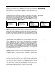
PCM 80 User Guide Lexicon Controlling PCM 80 Tempo Rate with MIDI Clock MIDI Tempo Control MIDI Out (MIDI Clock) MIDI In PCM 80 Tempo 0.2 Source set to MIDI Using the PCM 80 as a MIDI Clock Source MIDI In MIDI Out PCM 80 5-2 Control 3.6 Int Clock set to Transmit On Tempo 0.2 Source set to Internal Tempo 0.
MIDI Operation The configuration below shows the MIDI connections for controlling the PCM 80 simultaneously with MIDI Clocks from a sequencer, and messages from another MIDI controller. Note that the controller is set to "local control off" and the sequencer is set to "echo input". MIDI Thru MIDI In MIDI Out MIDI In MIDI In MIDI Out (MIDI Clock) PCM 80 Tempo 0.
PCM 80 User Guide Lexicon Controller quirks Some synthesizers and controllers cannot send the full range of MIDI program change messages (1-128). Others may appear to be able to send only 32, but actually have a bank mode that does let you send all 128 program change messages. Also, be aware that some MIDI devices use a program numbering system that uses 0-127 instead of 1-128. If in doubt, see the manual for your controller.
MIDI Operation Each PCM 80 preset has a unique soft knob patch that allows you to control the effect directly from Program or Register Banks mode with the ADJUST knob. You can also control the soft knob patch remotely from MIDI, or from the Foot Pedal. Controlling the Soft Knob with MIDI To control the soft knob with MIDI, set Control mode 3.1 (Receive) to the desired MIDI Channel. Set Control mode 3.5 (ADJUST) to the desired MIDI Controller such as Mod Wheel. MIDI ✱ADJUST 3.
PCM 80 User Guide Program Change Messages Lexicon Reception of MIDI Program Change and Bank Select messages can be selectively enabled/disabled from Control Mode parameter 3.0, MIDI Pgm Change. The manner in which the PCM 80 interprets these messages is determined by the value of this parameter as follows: Pgm Change: Off All Program Change and Bank select messages are ignored. Pgm+ and Pgm– will load the next higher or lower program in the current bank.
MIDI Operation SysEx Automation The PCM 80 will transmit SysEx automation messages when Control Mode parameter 3.4, MIDI Automation is set to On. All changes made by front panel operations are transmitted as PCM 80 SysEx messages. This is intended primarily for use by editor programs and in configurations where it is desirable for one or more PCM 80s to be slaved to a single PCM 80 acting as a master.
PCM 80 User Guide Lexicon Dynamic MIDI The following MIDI messages are available as Dynamic MIDI patch sources: MIDI Controllers 1-119 Pitch Bend After Touch (Polyphonic and Channel combined) Velocity (Note On) Last Note Low Note High Note Tempo (40–400BPM is converted to controller range 0-127) Clock Commands These MIDI messages are also available as threshold sources for several Modulation parameters: AR Env, Latch, Sw 1 and Sw 2. They may also be used as a tap source for controlling Tempo.
MIDI Operation MIDI Implementation Chart Lexicon PCM 80 Digital Effects System Function Transmitted Recognized Remarks Basic Channel Default Changed 1 1-16 1 1-16 Mode Default Messages Altered X X Mode 1, 3 X X X 0-127 Last Note, Low Note, High Note used as controllers used as controller Note Number Velocity Note ON Note OFF X O 9n v = 1-127 After Touch Keys Channel X X X O X O OX OX ADJUST, Footpedal, Footswitch 1, and Footswitch 2 can be assigned controllers 1-119 for MIDI tra
PCM 80 User Guide 5-10 Lexicon
Troubleshooting 6 Troubleshooting This chapter is intended primarily to help you recognize some common error states which can be corrected from the PCM 80 front panel, or by simple means such as cable replacement. Any error states which are not covered here should be referred to your local dealer for service by a qualified technician. In a low-voltage, or "brown-out" condition, the PCM 80 will freeze in its current state. None of the controls will have any effect.
PCM 80 User Guide Operational Problems Lexicon The PCM 80 will not lock onto an incoming digital signal. Check the cables that you are using. DO NOT USE ANALOG AUDIO CABLE TO CONNECT DIGITAL AUDIO. Also check to make sure that your input signal complies with S/PDIF format standards. The PCM 80 will recognize AES professional format signals from an appropriate connector, but will not necessarily read and transmit encoded information accurately.
Troubleshooting You can restore the PCM 80 to its default state without erasing registers by restoring the factory default setup: 1. Press Control. 2. 3. Use the Up and Down buttons to locate Row 4 Setup. Turn SELECT to 4.1 Load. 4. 5. Turn ADJUST counterclockwise to select "Factory Settings". Press Load/✱. The PCM 80 will display the message "Setup restored".
PCM 80 User Guide Lexicon Reinitialization Reinitializing will erase all registers and setups The following procedure will return the PCM 80 to the state it was in when shipped from the factory. This includes erasing all registers and setups, as well as restoring all of the default settings: 1. Press Control. 2. Use the Up and Down buttons to locate Row 1 System. 3. 4. Turn SELECT to 1.8 Initialize. Press Store. The PCM 80 will display the message "Are you sure? (Press STORE).
Specifications 7 PCM 80 Specifications Audio Input Connectors: Impedance: A/D Dynamic Range: Levels: CMRR: Audio Output Connectors: Impedance: D/A Dynamic Range: Levels: Protection: A/D Performance D/A Performance A/A Performance Frequency Response: Crosstalk: S/N Ratio: THD: Dynamic Range: Delay: Frequency Response: Crosstalk: S/N Ratio: THD: Dynamic Range: Delay: Frequency Response: Crosstalk: S/N Ratio: THD: Dynamic Range: Combined 3 pole XLR and 1/4 inch T/R/S phone jacks (2) 0 dB/BAL switch
PCM 80 User Guide Lexicon Digital Audio Interface Internal Audio Data Paths Audio Memory Configuration External Memory Card Control Interface General Connectors: Coaxial, RCA type Format: conforms to S/PDIF IEC-958 consumer standards Sample Rates: 44.
Lexicon Inc.