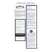
IMPORTANT SAFETY INSTRUCTIONS WARNING FOR YOUR PROTECTION PLEASE READ THE FOLLOWING: KEEP THESE INSTRUCTIONS HEED ALL WARNINGS FOLLOW ALL INSTRUCTIONS the apparatus shall not be exposed to dripping or splashing liquid and no object filled withi liquid, such as vases, shall be placed on the apparatus. CLEAN ONLY WITH A DRY CLOTH. DO NOT BLOCK ANY OF THE VENTILATION OPENINGS. INSTALL IN ACCORDANCE WITH THE MANUFACTURER’S INSTRUCTIONS.
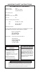
IMPORTANT SAFETY INSTRUCTIONS DECLARATION OF CONFORMITY Manufacturer’s Name: Lexicon® Manufacturer’s Address: 8760 S. Sandy Parkway Sandy, Utah 84070, USA declares that the product: Product name: PCM96 Note: Product name may be suffixed by the EU. Product option: None conforms to the following Product Specifications: Safety: IEC 60065 (7th ed.
Warranty This warranty is valid only for the original purchaser and only in the United States. If outside the United States please contact the local Lexicon® distributor. 1. The warranty registration card that accompanies this product must be mailed within 30 days after purchase date to validate this warranty. Proofof-purchase is considered to be the burden of the consumer. 2. Lexicon Professional warrants this product, when bought and used solely within the U.S.
Introduction.................................................................... 1 The Front Panel ............................................................... 3 The Rear Panel ................................................................. 5 USing the PCM 96 ............................................................. 7 Powering Up the PCM 96.............................................. 7 The Preset Screen...........................................................
Channel Map (How Channels Map to Machines).......... 28 Bank Dump................................................................... 28 Reverse Bank Dump (Bank “Load”)............................... 28 Continuous Controllers.................................................. 28 Soft Row Parameter/MIDI CC Map.............................. 29 Bank/Preset Map............................................................ 29 MIDI SysEx Implementation......................................... 30 The Algorithms.......
Introduction Congratulations and thank you for purchasing the PCM96 Reverb/Multi Effects Processor! The PCM96 offers legendary reverbs you’ve come to expect from Lexicon®, plus new mono reverbs, new room algorithms with selectable, reversible reflection patterns, and more. And you can add it all to your recording software via FireWireTM connectors supporting four 96kHz sample rate audio streams in each direction. The PCM96’s intuitive front panel makes operation simple.
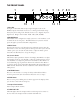
The Front Panel 1 3 2 MACHINE 4 SELECT 5 6 7 89 TAP/TEMPO STORE LOAD COMPARE FLASH BUSY BACK 10 11 12 13 1. Gain LEDs Each pair of Gain LEDs indicate input signal strength of each of the PCM96’s inputs. If the Audio Source is set to Analog (in the Audio Setup menu), they show analog levels. If Audio Source is set to Digital, they show digital levels. Range is from -18dB, -12dB, -6dB, -3dB, and 0dB. 2.
9. Power Button Press to turn the PCM96 on or off. 10. Display This high resolution, high contrast, and high viewing angle OLED (Organic LED) display shows menu and box configuration and status information. 11. BACK Pressing this button moves you up one level in the menu tree. Note that when a System preset is loaded, this button takes you to the System Mode Category Selection menu. When a Machine preset is loaded, the Back button takes you to the Machine Mode Category Selection menu. 12.
The Rear Panel 1 2 3 6 4 5 7 1. Power Jack Standard 3-pin IEC power connector. 100-240V, 50-60Hz automatic switching to correct voltage range. 2. Ethernet Inputs These RJ-45 connections are used to network PCM96 devices and control them via Ethernet. 3. MIDI IN Receives MIDI information from other MIDI equipment such as master keyboard controllers, MIDI foot controllers, sequencers and synthesizers. MIDI THRU Passes any MIDI data received without change.
6
Using the PCM96 Powering Up the PCM96 1. Plug in the power cord. 2. Press the Power button. 3. The Lexicon® logo appears, and remains until the boot process is complete. Next, the Preset screen appears, showing the currently loaded preset. The Preset Screen The Preset screen is the starting point for many of the instructions in this manual, so it’s a good idea to know how to get to the Preset screen. In most cases, pressing the Back button one or more times will take you back to the Preset screen.
Selecting Your Audio Source and Clock Source 1. Press the Machine button until the words “System View” appear in the Display. 1:ConcertHall->Flange 1:Single Stereo Config 96 48 (System View) 2. Press the Select knob. The System Menu appears. System Menu Version 1.0 +Audio Setup +System Control +MIDI Control 48 3. With Audio Setup highlighted, press the Select knob. The Audio Setup menu appears. |:Audio Setup Audio Source: ANALOG Clock Source: INTERNAL Clock Rate: 48KHz (Lock) 48 A B C 4.
System Presets and Machine Presets also have User and Card categories, where you can access user-edited presets. Presets in the User category are stored on the PCM96, and presets in the Card category are stored on a Compact Flash card. To select a different category 1. From the Preset screen, press the Back button. The Category Selection screen appears.
Note that pressing the Back button or the Select knob have different results depending on what kind of preset is loaded. The following diagram shows what happens when you press the Select knob, Back button, and Machine button in both System View and Machine View.
0:Med Hall 1:PreDelay 2:MidRT 2:ReverbTime 3:RvbOutFreq 48 :14ms :1.59s :4750.0Hz Configuration Icon (Machine Preset) Press the Machine button repeatedly to cycle through the virtual machines in a System Preset, and eventually back to the System Preset. Editing a Preset To edit a System Preset, you must edit the virtual machines within it. Press the Machine button to cycle through the virtual machines within a System Preset.
Storing a Preset Once you’ve edited a preset, you can store it on the PCM96 (in the User category) or on a Compact Flash card (in the Card category). Note: When you first insert a Compact Flash card, you may receive the message “Card Needs Initializing.” Refer to page 13 for instructions on how to initialize a Compact Flash card. 1. From the Preset screen, press the Store button. The Save As screen appears. Select Knob -> Change Position ʻAʼ Knob -> Change Letter Save As: Single Stereo Config 2.
Initializing/formatting a Compact Flash Card To initialize or format a Compact Flash card: 1. 2. 3. 4. 5. 6. Press the Back button until the Preset screen appears. Press the Machine button until System View is displayed. Press the Select knob to enter the System Menu. Turn the Select knob until Card Config is highlighted. Press the Select knob to access the Compact Flash Menu. Press Knob B to Format the card OR press Knob C to initialize the card.
DSP Configurations The PCM96 processor can be divided in up to four virtual machines, each of which can run its own algorithm. This lets you route signals from each input through a variety of algorithm combinations. The PCM96 can use up to two physical inputs and two physical outputs at a time; configurations for the physical inputs and outputs are described below.
The PCM96 Plug-IN The plug-in lets you add PCM96 reverbs and effects to projects on your Digital Audio Workstation (DAW). Installing the Plug-In software To install the PCM96 plug-in: 1. Double-click the PCM96_Installer x.x.x.x.dmg file (where “x.x.x.x.” is the version number) on the included DVD. The dmg file opens. 2. Double-click the PCM96_Installer x.x.x.x.dmg to begin the installer. 3. Follow the on-screen instructions to complete installation. 4.
In the second control area, you can adjust the soft row parameters by clicking on and moving the sliders. Note that the soft row parameters vary from preset to preset. Click the down arrow in the lower right corner to open the third control area. 16 In the third control area (located at the bottom of the plug-in), you can adjust all the parameters in the preset by clicking on and moving the sliders.
tons in the row at the top of the third control area (in the example above, I/O Levels, Input Control, Shape, etc.). Some parameters appear as dropdown menus; click the menu to open it, and click on an option to select it. When you move a parameter’s slider, an arrow appears where the slider’s default position is. To return a preset to its default, click on the arrow or move the slider toward the arrow until the arrow disappears.
PCM96 Setup Dialog When you click the PCM96 Communication button in the PCM96 Control Panel, the PCM96 Setup dialog appears. Communications Interface Select your computer’s connection to the PCM96 here. Choose from FirewireTM or “Ethernet X,” where “X” is a number corresponding to your computer’s network interface card. Driver Buffer Setting This control manages latency.
Networking This section provides a step-by-step guide on how to properly connect the PCM96 to a Local Area Network (LAN) for several different network architectures. The first topology is a simple direct connection using the provided Ethernet cable. The second method describes how to connect and configure several PCM96 units to create an isolated network using an Ethernet switch with static or with DHCP.
Subnet A small network within a larger network. For example, a TCP/IP network might be a subnet of a venue’s network, which could include computers throughout the building, or a network might be divided into subnets. For example, in a large installation, there may be one subnet per rack or room. DHCP (Dynamic Host Configuration Protocol) This is a protocol for automatically assigning IP addresses to devices on a network.
Virtual Private Networks (VPN) Virtual private networks (VPN) provide an encrypted connection (or tunnel) between networks or between a network and a user over a public network (such as the Internet). Instead of using a dedicated, real-world connection such as a leased line, a VPN uses virtual connections through the public network.
• • PC running the System Architect software Hub / Switch (if used) If you fail to see a link light try removing and reinserting the cable or trying a different, known good, cable. Also, make sure that you are using the correct cable. Ping There is a simple utility built into OS-X that tests the network connection between two devices. The following steps outline how to use this utility. 1. In the Applications folder, double click the Terminal icon. 2.
System Menu The System Menu lets you adjust several settings in the PCM96. To access the System Menu, press the Select knob while a System Preset is loaded. The System Menu contains sub-menus and options. Sub-menus contain options and/or more sub-menus. To enter a sub-menu, highlight it with the Select knob and press the Select knob. Options contain values that you can adjust (indicated by a colon followed by a value, for example, “Audio Source: ANALOG”).
transmitting device is paused. Mode - Select “Consumer” to send information in S/PDIF format. Select “Professional” to send information in AES format. Confidence Error - “0” indicates no problem. “1” indicates the PCM96 is detecting excessive jitter or noise on the digital audio line. No data has been corrupted, but corrective action should be taken. Sample Slip - An unchanging number indicates you are not slipping samples.
Bank Dump Lets you copy an entire bank of presets from the PCM96 to another device via MIDI. (For a map of banks and presets, see page 29; to see the current preset’s bank number, press Knob C while viewing the Preset screen.) When Bank Dump is highlighted, turn the corresponding B or C Knob to select a bank. Press the corresponding B or C Knob to send the bank to the connected device.
Machine Menu The Machine menu lets you adjust settings for a single virtual machine. To access the Machine menu, press the Select knob while a Machine Preset is loaded. The sub-menus vary depending on what algorithm is active. Soft Row Setup This sub-menu lets you assign parameters to a Machine Preset’s soft row. The soft row is the list of parameters that appears below a Machine Preset’s name in the Preset screen.
Using MIDI The MIDI Control menu is where all MIDI related control is changed. See page 24 for information about the MIDI Control menu. MIDI Implementation The PCM96 offers MIDI implementation for use with external MIDI hardware and software controllers. You can connect up to three PCM96 units to a single MIDI controller. You can also slave two or more PCM96 units together by connecting a cable from the MIDI Out port of the master to the MIDI In port of the slave.
Channel Map (how channels map to machines) Channel Usage Base System Level Channel Base + 1 Virtual machine 1 Description Use for loading System presets. This is the PCM96 unit’s base channel. The next four channels apply to this PCM96 unit’s virtual machines. Changes parameters in one virtual machine in a System preset on the PCM96 unit with base channel 0. Use for loading machine presets and changing parameters for machine #1.
Soft Row parameter/MIDI CC Map Soft Row Parameter Parameter #1 Parameter #2 Parameter #3 Parameter #4 Parameter #5 Parameter #6 Parameter #7 Parameter #8 MIDI CC CC 48 CC 49 CC 50 CC 51 CC 52 CC 53 CC 54 CC 55 Bank/Preset Map Bank Mono Internal Flash Bank 1 Mono Internal Flash Bank 2 Stereo Internal Flash Bank 1 Stereo Internal Flash Bank 2 System Internal Flash Bank 1 System Internal Flash Bank 2 Presets Mono User Onboard Flash Category Presets 1 – 128 Mono User Onboard Flash Category Presets 129 – 25
MIDI SysEx Implementation Command 0: Request Preset Dump When this command is received by the PCM96, it will respond with a preset dump of the requested preset. If the preset does not exist, the PCM96 will not respond. Only presets from User banks may be requested. Factory banks will not be transmitted.
Command 2: Request Preset Bank Dump When this command is received by the PCM96, it will respond with a series of preset dumps for all presets in the bank. Blank presets will be transmitted in a special form. Only presets from User banks may be requested. Factory banks will not be transmitted.
32
The Algorithms Chamber (Stereo and Mono) Chamber is a complex miniature-space effect resembling an echo chamber at its smaller settings and, at its larger ones, a small performance space with a more rapid build-up of reflection density than a hall. Reverberant tails are randomized. Random Delay (Stereo and Mono) Random Delays provide no-holds-barred control over delays. These algorithms feature one delay line per input channel. Each delay line has two outputs, called “voices.
Random Delays are similar to Simple Delays, but are especially useful for: • Multitap Tape Loops Feedback can be used to recirculate delays. Appropriate use of highpass and lowpass filters emulates the bandpass effects of multi-generational tape loops (hiss not included). Feedback diffusion allows emulation of azimuth misalignment – a hallmark of the sound.
Random Hall (Stereo and Mono) Random Hall is a hall effect with gradual build-up, well suited to complex sounds like orchestral music. Its reverberators change over time in controlled random ways to avoid the buildup of tinny, grainy, metallic, or other colorations. The modulation can be noticeable and is often a desirable effect. The early reflections are user adjustable in amplitude and delay. Some skill is needed to set useful reflection patterns.
Resonant Chords (Stereo and Mono) The Resonant Chord algorithm uses impulsive energy at the inputs to excite six resonant voices (notes). The level, pitch, duration, and high-frequency cutoff of the overtones for each voice are separately controllable. Each voice can be panned independently. The voices resonate to some degree with any input, but the most effective excitation contains all frequencies, like percussion.
round-robin. For example, if MIDI note numbers are used to assign pitch, the resonators will constantly be re-tuned to the pitches of the last six MIDI notes received. (This can produce an effect similar to playing a piano with the sustain pedal depressed.) In Res2>Plate, pitches are assigned to the six resonators diatonically, harmonized with the key, scale, and root of your choice.
38
The parameters The PCM 96 contains hundreds of presets, covering just about every possible need. But you can refine and customize any preset by adjusting its parameters. Parameters are the building blocks within each preset that determine how it sounds and behaves. Each algorithm contains a set of parameters, and a variety of those parameters (sometimes from more than one algorithm) are combined to create a preset.
Category (Room) This parameter lets you select a specific category from which a room response may be chosen. Changes here have a direct effect on the Pattern Selector parameter. Chorus Depth (Concert Hall) This parameter controls the amount of randomization of the chorus tap. Higher values are generally preferred in order to minimize reverb coloration. Pitch effects may result and are closely tied to the Reverb Chorus Rate parameter.
The actual feedback level is modified by the Master Echo Feedback parameter, if present. The master value is a percentage (0-100%) that is applied to the Echo Feedback level. Feedback Diffusion Feedback Diffusion is similar to Input Diffusion, except that it is applied to a delayed signal that is being added back into the input. Feedback Level This parameter determines the feedback level for a particular voice. It is controlled independently of the voice’s output level.
Master Reflection Delay (Reflection Time Master) Controls all reflection delays in the algorithm. Each reflection delay voice has its nominal delay time adjusted by this percentage. MidRT MidRT is the mid frequency reverb time. As such, it is one of the primary controls affecting the length of the reverb tail. At low values, it models a space with absorbent walls—a signal won’t bounce many times before it dissipates. At high values, the walls are flat and extremely reflective.
Resonance Master Controls all voices in the algorithm. Each voice has its nominal resonance adjusted by this percentage. Resonance Tuning Master Affects all voices in the algorithm. Each voice has its nominal resonance adjusted by this value. In the musical world, the tuning reference is A=440. This means that the note A (above middle C) is equivalent to 440 Hz. Changing the master tuning causes all notes to be sharp or flat.
to bounce around. When the room size is small, the “walls” of this space are closer together and the resultant reflection density increases. When the room size is large, that density decreases. The most natural reverbs use room sizes that vary from about 24 meters to 45 meters or so, but there are many useful reverbs that are outside of this range. There is a relationship between this parameter and the MidRT parameter. Please see the MidRT parameter for clarification.
Signal Type Selects the type of signal to be created by the signal generator. The types of signal are: • • • • • • • • Sine Wave — When this is selected the signal frequency parameter is used to control frequency. Sweep Up — 20Hz to 20KHz sweep. When this is selected the signal rate parameter is used to control rate. Sweep Down — 20Khz to 20Hz sweep. When this is selected the signal rate parameter is used to control rate. Pink Click — Broadband impulse.
Type This parameter lets you configure a filter as any of 4 basic types, in order: • • • • Lowpass Highpass Bandpass Notch (Band-reject) The filter provides a subset of filter types available to a Biquad filter. Wet Dry Mix Wet Dry Mix is the proportion of wet (processed) signal to dry (unprocessed) signal.
PCM 96 Menu Navigation Map - System View and Machine View 47
PCM 96 Menu Navigation Map - Stereo Hall Algorithms 48
PCM 96 Menu Navigation Map - Stereo chamber and room Algorithms 49
PCM 96 Menu Navigation Map - Stereo Delay Algorithms 50
PCM 96 Menu Navigation Map - Stereo Effects Algorithms 51
PCM 96 Menu Navigation Map - Mono Hall Algorithms 52
54
56
PCM96 Specifications Analog Inputs Connectors Impedance Level (for 0 dbFS) Freq Response @96K A/D Conversion A/D Dyn Range THD Crosstalk @ 1Khz Two, Female XLR 20K Ohm, balanced +4dBu mode: +20dBu –10dBV mode: 8.2dBu 20Hz to 40KHz, +0/–3dB 24 bits >112 dB unweighted, 115dB A-weighted <.
Clock Jitter Intrinsic Jitter Gain Exceeds AES3 Amendment 1 Exceeds AES3 Amendment 1 Control Interfaces MIDI ** In/Out/Thru **supports program change Algorithms Chamber Random Delay Random Hall Plate Dual Delay Resonant Chords Chorus/Flange Concert Hall Room Hall Signal Generator Stereo and Mono Stereo and Mono Stereo and Mono Stereo and Mono Stereo and Mono Stereo and Mono Stereo only Stereo only Stereo and Mono Stereo and Mono Storage Media Type I Compact Flash Can hold up to 1536 user preset
Dimensions Rack Units Size 1U 19.0” W x 1.75” H x 12.5” D (483mm x 44.5mm x 317.5mm) Weight 8.65 lbs Regulatory Approvals FCC CE UL cUL TUV Class A EN55103-1, EN55103-2 UL1419 C22.
MIDI Implementation Chart Function Basic Channel Mode Note Number Velocity After Touch Pitch Bend Control Change Program Change Bank Select System Exclusive System Common Default Changed Default Messages Altered True Voice Note ON Note OFF Keys Channel Song Position Song Select Tune Request System Clock Real Time Commands Aux Local ON/OFF Messages All Notes OFF Active Sensing System Reset Notes Mode 1: OMNI ON, POLY Mode 3: OMNI OFF, POLY 60 Transmitted X X X X X Recognized Remarks 1-16 X N/A X X X
61
Harman Music Group 8760 South Sandy Parkway | Sandy, Utah 84070 U.S.A. Phone: (801)-568-7660 | Fax: (801)-568-7662 PCM96 Copyright 2008 Lexicon Professional® Questions or comments? Email us at: customer@lexiconpro.com or visit us online at www.lexiconpro.