4600 MFP Option Printer and Scanner Setup Guide for the C782n printer February 2007 www.lexmark.
Stability Information CAUTION: Certain floor-mounted configurations require additional furniture for stability. More information is available on our Lexmark Web site at www.lexmark.com/multifunctionprinters.
English
Edition: February 2007 The following paragraph does not apply to any country where such provisions are inconsistent with local law: LEXMARK INTERNATIONAL, INC., PROVIDES THIS PUBLICATION “AS IS” WITHOUT WARRANTY OF ANY KIND, EITHER EXPRESS OR IMPLIED, INCLUDING, BUT NOT LIMITED TO, THE IMPLIED WARRANTIES OF MERCHANTABILITY OR FITNESS FOR A PARTICULAR PURPOSE. Some states do not allow disclaimer of express or implied warranties in certain transactions; therefore, this statement may not apply to you.
CAUTION: This product uses a laser. Use of controls or adjustments or performance of procedures other than those specified herein may result in hazardous radiation exposure. CAUTION: This product contains mercury in the lamp (<5mg Hg). Disposal of mercury may be regulated due to environmental considerations. For disposal or recycling information, contact your local authorities or the Electronic Industries Alliance: www.eiae.org. CAUTION: The printer weighs 48–82 kg (105–181 lb).
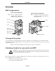
Overview Overview MFP configurations Printer stand configuration Scanner cabinet configuration Note: Do not use a printer stand with a configured stack containing a 2000-sheet, high-capacity drawer. Note: Do not place a scanner shelf on top of a configured stack containing a 2000-sheet, high-capacity drawer.
Overview • Keep the equipment away from the direct airflow of air conditioners, heaters, or ventilators. • Keep the equipment free of sunlight, humidity extremes, or temperature fluctuations. • Keep the equipment clean, dry, and free of dust. Customizing your MFP option You can customize your MFP with various input, output, and memory options. Note: Leave all components and hardware in the boxes until you are ready to install them.
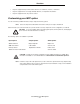
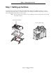
Step 1: Setting up furniture Step 1: Setting up furniture If you purchased your scanner as a bundle (printer shipped with: a duplex unit, two 500-sheet drawers, a scanner, a scanner shelf, and a printer stand), or you purchased your scanner with optional furniture and/or drawers, set up your printer starting with the printer stand or scanner cabinet. Note: Place the furniture in the location you are assembling your printer and follow the instructions that came with the furniture.
Step 2: Installing optional drawers Step 2: Installing optional drawers Note: Do not place a scanner shelf on top of a configured stack containing a 2000-sheet, high-capacity drawer. Note: Do not use a printer stand with a configured stack containing a 2000-sheet, high-capacity drawer. If you are installing a 2000-sheet drawer, install it before any other optional drawer. Follow the installation setup instructions that came with each drawer, and then go to Step 3 to install the duplex unit.
Step 5: Preparing the printer Step 5: Preparing the printer Removing the print cartridge packaging Note: If you are installing a scanner after initial printer setup, the print cartridge packaging has already been removed. 1 Remove all exterior packing tape. 2 Open the front door. 3 Remove and discard the packing strips.
Step 5: Preparing the printer 4 Remove and discard the tabs from the cartridges. 5 Lift up, and then pull out to remove each toner cartridge. 6 Place all toner cartridges on a clean, flat surface. 7 Remove the image transfer unit (ITU) detentioner and protective cover.
Step 5: Preparing the printer 8 Shake each toner cartridge front to back and side to side. 9 Remove each toner cartridge cover. Warning: Do not touch the photoconductor. 10 Reinsert the toner cartridges into the printer. Each toner cartridge will drop down and snap into place. 11 Close the front cover.
Step 5: Preparing the printer Loading paper Complete these instructions to load paper into any of the standard or optional trays. All trays are loaded in the same way. 1 Remove the tray. 2 Adjust the length and width guides to the correct position for the size of paper you are loading. 3 Flex the sheets of paper back and forth to loosen them, and then fan them. Do not fold or crease the paper. Straighten the edges of the stack on a level surface. 4 Place the paper into the tray.
Step 6: Installing an optional operator panel cover Step 6: Installing an optional operator panel cover An optional operator panel cover is provided with the MFP. To install the optional cover: 1 Locate the cover bracket packaged with your MFP. 2 Remove the backing from the tape on the rear of the cover bracket. 3 Align the holes in the cover bracket with the buttons on the operator panel, and then press it into place. 4 Align the cover with the cover bracket.
Step 7: Attaching a scanner shelf Step 7: Attaching a scanner shelf 1 Remove the top cover from the printer. You will not need the cover when the scanner shelf is attached. Store the cover; it will be needed if you remove the scanner shelf. 2 Remove the backing from the tape on the scanner shelf bottom. 3 Align and insert the scanner shelf mounting brackets into the slots on top of the printer.
Step 8: Installing the scanner on a scanner shelf 4 Make sure the scanner shelf is positioned securely. 5 Attach the plastic bracket to the scanner shelf. 6 Place the tips of the wire bail into the ends of the plastic brackets so that the bail curves downward. The wire bail came with the printer and rests in the standard output bin when installed. 1 2 Step 8: Installing the scanner on a scanner shelf 1 Place the scanner on the scanner shelf.
Step 8: Installing the scanner on a scanner shelf 3 Align the hinges on the scanner top with the slots in the scanner, and then lower the scanner top onto the scanner. For information on removing the scanner top, see “Removing the scanner top” in the User’s Guide located on the4600 MFP Software and Documentation CD. 4 Connect the two scanner cables. Note: To prevent errors and scanner malfunction, make sure the scanner cable thumbscrews are tightened securely.
Step 9: Unlocking the scanner Step 9: Unlocking the scanner 1 Locate the lock switch on the side of the scanner, and then slide the switch down. 2 Lift the scanner feed tray up until it locks into position. Step 10: Installing the scanner without a scanner shelf 1 Remove the scanner from the carton. 2 Place the scanner on a table, scanner cabinet, or other flat surface.
Step 10: Installing the scanner without a scanner shelf 3 Align the hinges on the scanner top with the slots in the scanner, and then lower the scanner top onto the scanner. For information on removing the scanner top, see “Removing the scanner top” in the User’s Guide located on the4600 MFP Software and Documentation CD. 4 Connect the two scanner cables. Note: To prevent errors and scanner malfunction, make sure the scanner cable thumbscrews are tightened securely.
Step 11: Installing output options Step 11: Installing output options If you purchased an output option (output expander, 5-bin mailbox, or StapleSmart™ finisher), follow these steps: 1 Remove the top cover from the printer. You will not need the cover when the output option is attached. Store the cover; it will be needed if you remove the output option. 2 Remove the option from the box, and follow the installation setup instructions that came with the option.
Step 12: Installing memory, option, or interface cards Step 12: Installing memory, option, or interface cards Note: If you purchased the printer as part of a bundle, memory cards have been preinstalled. CAUTION:If you are installing memory or option cards sometime after setting up the printer, turn the printer off, and unplug the power cord from the wall outlet before continuing. The instructions in this section help you install the interface card, memory card, and “optionadded” firmware card.
Step 12: Installing memory, option, or interface cards Installing a memory card Note: Printer memory cards designed for other Lexmark printers may not work with the printer. 1 Remove the system board access cover from the back of the printer. (See Accessing the printer system board.) Warning: Printer memory cards are easily damaged by static electricity. Touch something metal such as the printer frame before you touch a memory card. 2 Push open the latches on both ends of the memory card connector.
Step 12: Installing memory, option, or interface cards Installing an “option-added” firmware card Note: “Option-added” firmware cards designed for other Lexmark printers will not work with the printer. 1 Remove the system board access cover from the back of the printer. (See Accessing the printer system board.) Note: If an “option-added” firmware card has already been installed, you must remove it. 2 Unpack the “option-added” firmware card.
Step 12: Installing memory, option, or interface cards Installing the interface card Warning: Interface cards are easily damaged by static electricity. Touch something metal such as the printer frame before you touch an interface card. 1 Remove the system board access cover from the back of the printer. (See Accessing the printer system board.) 2 Remove the screw and cover plate, and save them.
Step 12: Installing memory, option, or interface cards 3 Unpack the scanner interface card and cable. Save the packaging materials. a Connect the USB interconnect cable to the card. Connector Interface card USB interconnect cable b Connect the USB interconnect cable to the system board.
Step 12: Installing memory, option, or interface cards 4 Align the connection points on the card with the connector on the system board, and then push the top of the card firmly into the system board connector. 5 Insert and tighten the screws to secure the card. Replacing the access cover plate After you have installed options on the printer system board, follow these steps to reattach the access cover plate.
Step 13: Attaching cables to the printer and the scanner Step 13: Attaching cables to the printer and the scanner CAUTION: Do not use the fax feature during a lightning storm. Do not set up this product or make any electrical or cabling connections, such as the power cord or telephone, during a lightning storm. CAUTION:Connect the power cord to a properly grounded electrical outlet that is near the product and easily accessible. 1 Connect the scanner cable to the scanner and printer.
Step 13: Attaching cables to the printer and the scanner 3 Connect the RJ-11 telephone fax line cable into the left modem port on the back of the scanner. Note: Germany: Use only the German TAE type F adapter shipped with this product, because it contains a billing tone filter. The adapter is designed only for the F connector of the German wall outlet. This must be the only device attached to the NFN wall receptacle.
Step 13: Attaching cables to the printer and the scanner 6 Connect the power cord to the scanner. Use the power cord from the printer box. 7 Plug the power cord into a properly-grounded outlet. 1 2 If you have a 2000-sheet drawer, follow the steps below: 1 Connect the 2000-sheet drawer to the scanner using the cord from the scanner box. 2 Connect the 2000-sheet drawer to the printer using the cord from the 2000-sheet drawer box.
Step 14: Installing drivers for the printer, MFP, and other options Step 14: Installing drivers for the printer, MFP, and other options After attaching the power cables and turning on your computer, you will need to install two sets of drivers. First, install the printer drivers located on the Software and Documentation CD that came with your printer, then install the MFP drivers located on the4600 MFP Software and Documentation CD that came with the MFP.
Step 15: Setting up fax and IP addresses Step 15: Setting up fax and IP addresses Fax setup When you first turn on the MFP or if the MFP has been off for an extended time, Set clock will appear.
Step 15: Setting up fax and IP addresses Assigning a printer IP address If the network is using DHCP, an IP address is automatically assigned after connecting the network cable to the printer. 1 Look for the address under the “TCP/IP” heading on the network setup page. To print a network setup page 2 a Touch the key icon on the MFP control panel. b Touch Reports. c Touch Network Setup Page or Network Setup Page. Go to Performing browser fax setup on page 34.
Step 15: Setting up fax and IP addresses Performing browser fax setup Note: Configuration is a task usually done by a system support person. If you are prompted for a password during the following instructions, see your system support person for help. 1 Type the IP address of the MFP in the URL field of your browser (for example, http://192.168.236.24), and then press Enter. 2 Click Configuration. 3 Under the MFP heading, click Fax Setup. 4 Click Configuration.
Step 16: Verifying MFP setup Step 16: Verifying MFP setup Printing a menu settings page 1 Touch the key icon on the MFP control panel. 2 Touch Reports. 3 Touch Menu Settings Page. 4 Verify the options you installed are correctly listed under “Installed Features” and “Printer Information.” Printing the Help pages We recommend you store this information in a convenient location near the printer. 1 Touch the key icon on the MFP control panel. 2 Touch Help. 3 Touch Print all guides.
Step 16: Verifying MFP setup 4 Enter the fax number using the numbers on the touch screen or keypad. Add recipients by touching next and then entering the recipient's telephone number or shortcut number, or search the address book. Note: To place a two-second dialing pause within a fax number, touch the Dial Pause button. The dial pause will appear as a comma in the Fax to: box. Use this feature if you need to dial an outside line first. 5 Touch Fax It.
Step 17: Solving setup problems Step 17: Solving setup problems Problem Solution Nothing appears on the scanner display. The scanner and the printer are not talking to each other. 1 Turn the printer off and then back on. 2 Turn the printer off, and unplug the scanner. Make sure all cables and cords are connected, and then plug the scanner in before turning on the printer. The control panel is not responding. Make sure the printer is turned on.