Lexmark OptraTM C710 5016-001 • Table of Contents • Start Diagnostics • Safety and Notices • Trademarks • Index Lexmark and Lexmark with diamond design are trademarks of Lexmark International, Inc., registered in the United States and/or other countries.
5016-001 Edition: May 2001 The following paragraph does not apply to any country where such provisions are inconsistent with local law: LEXMARK INTERNATIONAL, INC. PROVIDES THIS PUBLICATION “AS IS” WITHOUT WARRANTY OF ANY KIND, EITHER EXPRESS OR IMPLIED, INCLUDING, BUT NOT LIMITED TO, THE IMPLIED WARRANTIES OF MERCHANTABILITY OR FITNESS FOR A PARTICULAR PURPOSE. Some states do not allow disclaimer of express or implied warranties in certain transactions; therefore, this statement may not apply to you.
5016-001 Table of Contents Notices and Safety Information . . . . . . . . . . . . . . . . . . . . . . . . . . . . ix Laser Notices . . . . . . . . . . . . . . . . . . . . . . . . . . . . . . . . . . . . . . . . . . . ix General Information . . . . . . . . . . . . . . . . . . . . . . . . . . . . . . . . . . . . 1-1 Models . . . . . . . . . . . . . . . . . . . . . . . . . . . . . . . . . . . . . . . . . . . . . . . 1-2 Standard Features . . . . . . . . . . . . . . . . . . . . . . . . . . . . . . . . . . . .
5016-001 Carriage Unit Service Check . . . . . . . . . . . . . . . . . . . . . . . . . . . .2-39 Coupling Unit Service Check. . . . . . . . . . . . . . . . . . . . . . . . . . . .2-42 Cover Interlock Service Check . . . . . . . . . . . . . . . . . . . . . . . . . .2-45 Developer/Paper Feed Motor Service Check . . . . . . . . . . . . . . .2-48 Erase Lamp Service Check . . . . . . . . . . . . . . . . . . . . . . . . . . . . .2-50 Fuser Cold Service Check. . . . . . . . . . . . . . . . . . . . . . . . . . . .
016-001 Toner Low/Empty Sensor Service Check . . . . . . . . . . . . . . . . . 2-97 Transfer Roll Service Check . . . . . . . . . . . . . . . . . . . . . . . . . . . 2-98 Tray 1 (Integrated Tray) Service Check . . . . . . . . . . . . . . . . . . . 2-99 Options Service Checks . . . . . . . . . . . . . . . . . . . . . . . . . . . . . . . . 2-106 Flash Memory Option(s) Service Check . . . . . . . . . . . . . . . . . 2-106 DRAM Memory Option(s) Service Check. . . . . . . . . . . . . . . . .
5016-001 Error Log . . . . . . . . . . . . . . . . . . . . . . . . . . . . . . . . . . . . . . . . . . . . .3-22 Viewing the Error Log . . . . . . . . . . . . . . . . . . . . . . . . . . . . . . . . .3-22 Clearing the Error Log . . . . . . . . . . . . . . . . . . . . . . . . . . . . . . . . .3-22 Restore EP Factory Defaults . . . . . . . . . . . . . . . . . . . . . . . . . . . .3-22 Exiting Diagnostic Mode . . . . . . . . . . . . . . . . . . . . . . . . . . . . . . . . .3-23 Repair Information . . . . . . .
5016-001 Paper Sensor Board. . . . . . . . . . . . . . . . . . . . . . . . . . . . . . . . . . Resist Sensor Board Removal . . . . . . . . . . . . . . . . . . . . . . . . . . Waste Toner Board Assembly Removal . . . . . . . . . . . . . . . . . . Fuser Unit . . . . . . . . . . . . . . . . . . . . . . . . . . . . . . . . . . . . . . . . . . . . Fuser Unit Removal . . . . . . . . . . . . . . . . . . . . . . . . . . . . . . . . . . Fuser Lamp Removal. . . . . . . . . . . . . . . . . . . . . . . . . . . . . . .
5016-001 How To Use The Parts Catalog . . . . . . . . . . . . . . . . . . . . . . . . . . . . .7-1 Assembly 1: Fuser . . . . . . . . . . . . . . . . . . . . . . . . . . . . . . . . . . . . . . .7-2 Assembly 2: Fuser . . . . . . . . . . . . . . . . . . . . . . . . . . . . . . . . . . . . . . .7-4 Assembly 3: Transfer . . . . . . . . . . . . . . . . . . . . . . . . . . . . . . . . . . . . .7-8 Assembly 4: Frames. . . . . . . . . . . . . . . . . . . . . . . . . . . . . . . . . . . . .
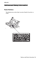
5016-001 Notices and Safety Information Laser Notices The following laser notice labels may be affixed to this printer as shown: Notices and Safety Information ix
5016-001 Laser Notice The printer is certified in the U.S. to conform to the requirements of DHHS 21 CFR Subchapter J for Class I (1) laser products, and elsewhere is certified as a Class I laser product conforming to the requirements of IEC 825. Class I laser products are not considered to be hazardous. The printer contains internally a Class IIIb (3b) laser that is nominally a 5 milliwatt gallium arsenide laser operating in the wavelength region of 770-795 nanometers.
5016-001 French Avis relatif à l’utilisation de laser Pour les Etats-Unis : cette imprimante est certifiée conforme aux provisions DHHS 21 CFR alinéa J concernant les produits laser de Classe I (1). Pour les autres pays : cette imprimante répond aux normes IEC 825 relatives aux produits laser de Classe I. Les produits laser de Classe I sont considérés comme des produits non dangereux.
5016-001 Spanish Avisos sobre el láser Se certifica que, en los EE.UU., esta impresora cumple los requisitos para los productos láser de Clase I (1) establecidos en el subcapítulo J de la norma CFR 21 del DHHS (Departamento de Sanidad y Servicios) y, en los demás países, reúne todas las condiciones expuestas en la norma IEC 825 para productos láser de Clase I (1). Los productos láser de Clase I no se consideran peligrosos.
5016-001 Dutch Laserinformatie De printer voldoet aan de eisen die gesteld worden aan een laserprodukt van klasse I. Voor de Verenigde Staten zijn deze eisen vastgelegd in DHHS 21 CFR Subchapter J, voor andere landen in IEC 825. Laserprodukten van klasse I worden niet als ongevaarlijk aangemerkt. De printer is voorzien van een laser van klasse IIIb (3b), dat wil zeggen een gallium arsenide-laser van 5 milliwatt met een golflengte van 770-795 nanometer.
5016-001 Finnish Huomautus laserlaitteesta Tämä kirjoitin on Yhdysvalloissa luokan I (1) laserlaitteiden DHHS 21 CFR Subchapter J -määrityksen mukainen ja muualla luokan I laserlaitteiden IEC 825 -määrityksen mukainen. Luokan I laserlaitteiden ei katsota olevan vaarallisia käyttäjälle. Kirjoittimessa on sisäinen luokan IIIb (3b) 5 milliwatin galliumarsenidilaser, joka toimii aaltoalueella 770 - 795 nanometriä.
5016-001 Swedish Laser-notis Denna skrivare är i USA certifierad att motsvara kraven i DHHS 21 CFR, underparagraf J för laserprodukter av Klass I (1). I andra länder uppfyller skrivaren kraven för laserprodukter av Klass I enligt kraven i IEC 825. Laserprodukter i Klass I anses ej hälsovådliga. Skrivaren har en inbyggd laser av Klass IIIb (3b) som består av en laserenhet av gallium-arsenid på 5 milliwatt som arbetar i våglängdsområdet 770795 nanometer.
5016-001 Catalàn Avís sobre el Làser Segons ha estat certificat als Estats Units, aquesta impressora compleix els requisits de DHHS 21 CFR, apartat J, pels productes làser de classe I (1), i segons ha estat certificat en altres llocs, és un producte làser de classe I que compleix els requisits d’IEC 825. Els productes làser de classe I no es consideren perillosos. Aquesta impressora conté un làser de classe IIIb (3b) d’arseniür de gal.li, nominalment de 5 mil.
5016-001 Japanese Laser Notice Chinese Laser Notice Notices and Safety Information xvii
5016-001 Korean Laser Notice xviii Service Manual
5016-001 Safety Information • This product is designed, tested and approved to meet strict • • global safety standards with the use of specific Lexmark components. The safety features of some parts may not always be obvious. Lexmark is not responsible for the use of other replacement parts. The maintenance information for this product has been prepared for use by a professional service person and is not intended to be used by others.
5016-001 Norme di sicurezza Italian • Il prodotto è stato progettato, testato e approvato in conformità • • a severi standard di sicurezza e per l’utilizzo con componenti Lexmark specifici. Le caratteristiche di sicurezza di alcune parti non sempre sono di immediata comprensione. Lexmark non è responsabile per l’utilizzo di parti di ricambio di altri produttori. Le informazioni riguardanti la manutenzione di questo prodotto sono indirizzate soltanto al personale di assistenza autorizzato.
5016-001 Pautas de Seguridad Spanish • Este producto se ha diseñado, verificado y aprobado para • • cumplir los más estrictos estándares de seguridad global usando los componentes específicos de Lexmark. Puede que las características de seguridad de algunas piezas no sean siempre evidentes. Lexmark no se hace responsable del uso de otras piezas de recambio. La información sobre el mantenimiento de este producto está dirigida exclusivamente al personal cualificado de mantenimiento.
5016-001 Informació de Seguretat Catalàn • Aquest producte està dissenyat, comprovat i aprovat per tal • • d'acomplir les estrictes normes de seguretat globals amb la utililització de components específics de Lexmark. Les característiques de seguretat d'algunes peces pot ser que no sempre siguin òbvies. Lexmark no es responsabilitza de l'us d'altres peces de recanvi. La informació pel manteniment d’aquest producte està orientada exclusivament a professionals i no està destinada a ningú que no ho sigui.
5016-001 Korean Notices and Safety Information xxiii
5016-001 xxiv Service Manual
5016-001 1. General Information The LexmarkTM OptraTM C710 is a letter quality page printer designed to attach to an IBM-compatible personal computer and most computer networks.
5016-001 Models The 5016-001 printer is available in the following models: Model Memory INA Options C710 32 MB N/A N/A C710n 32 MB 10 Base 100T N/A C710dn 64 MB 10 Base 100T • Additional 2x250 paper drawer • Duplex Standard Features Feature Description Printing Process Dry electrophotographic process using a laser diode. Performance • • • • Monochrome, Letter or A4 - up to 16 ppm. Color, Letter or A4 - up to 3ppm. Color transparencies, Letter or A4 - up to 1.8 ppm.
5016-001 Feature Description Maximum Duplex Print Speed (Mono/Color) 5/1.5 ppm (Letter and A4) Paper Input • Standard 250 sheet integrated input tray • Multipurpose feeder: 50 sheets Paper Output Top output bin: 250 sheets Media Size Supported A4, B5, Letter, Legal and Executive Physical Characteristics • Width: 18.5” (470mm), Depth 25.5” (645mm), Height 16.0” (405mm). • Height of 2nd drawer: 2 x 250 trays 8.9” (223mm). • Height of duplex option: 5.7” (145mm). • Weight: 79 lbs. (35.
5016-001 Feature Description Charging System Corona Development Non-magnetic mono-component Fusing System Hot roll fuser 170 degree C (Hot roll 30mm, backup roll 34mm) Operating Temperature Erase System Image Transfer System • 10 - 35 degrees C (50 - 95 degrees F) Light discharge (LED lamp) • Intermediate transfer (primary) • Transfer roller (secondary) PC Drum Photoconductor: OPC (organic photoconductor) Cleaning System Blade Printer Memory • 32MB SDRAM Note: Some models may ship with more mem
5016-001 Feature Description Tri-port Adapter Provides support for the following interfaces: • Serial RS-232C/RS-422A (which can also be configured to support a class 1 Fax modem. • High speed infrared local connections. • LocalTalk network connection. Parallel/USB Port Adapter IEEE 1284 adapter provides additional parallel and USP port. Infrared Adapter For use with the Tri-port adapter. Receives infrared beam from an IrDA-compatible workstation.
5016-001 Maintenance Approach The diagnostic information in this manual leads you to the correct field replaceable unit (FRU) or part. Use the service error codes, user status messages, user error messages, service checks, and diagnostic aids to determine the printer problem and repair the failure. After you complete the repair, perform tests as needed to verify the repair. Tools Required For Service • • • • • • • • • • • • • • Flat-blade screwdriver #1 Phillips screwdriver #2 Phillips screwdriver 7.
5016-001 Options The following options are available. Some options are not available in every country. Contact your point of purchase for options available in your country.
5016-001 Operational Theory Interlock Mechanism When the front cover assembly, fuser cover or cartridge cover is open, a CLOSE DOOR message displays indicating the interlock system is open. If the front door assembly or the fuser cover are closed, the door switch actuator 3 [A] moves in the direction of arrow [B]. When the cartridge door is closed the door switch actuator 1 [C] rotates in the direction shown by arrow [D] and activates the door switch [E] and laser switch [F].
5016-001 Sheet Bypass Paper Feed Unit Operation of the sheet bypass paper feed unit (multipurpose tray) When the sheet bypass tray is closed and printing is started, revolution of the developer/paper feed motor is transmitted to the clutch gear and timing clutch gear of the sheet bypass paper feed assembly. When the bypass paper feed clutch activates, the sheet bypass paper transfer roll is lowered and touches the paper in the tray.
5016-001 Detecting paper present A sheet of paper in the sheet bypass tray is detected by the sheet bypass paper detect sensor. When the sheet of paper is detected, the paper detect sensor turns off. When the sheet of paper is not detected, the sensor turns on.
5016-001 Paper Feed Unit Operation of the paper feed unit (tray 1) When the paper cassette (tray 1) is present in the printer, a flag molded in the right side of the tray contacts the release lever rotating the paper transfer roll, allowing it to contact the paper in the tray.
5016-001 Detecting paper size Paper size is determined by the paper size detect plate connecting the inner part of the partition plate which detects the paper size turning on the corresponding switch. It detects Legal, Letter, A4 or B5/EXE.
5016-001 Second Paper Feed Unit (Optional Paper Trays) Construction of the Second paper feed option The second paper feed unit consists of two separate feed units which are the same as the paper feed unit for tray 1, along with idler rollers above the paper feed units and paper guides on the side of the paper feed opening. The interconnect board assembly, drive module and LVPS for the option is located on the right side frame.
5016-001 Operation of the Second paper feed unit When the paper cassette (tray 1) is placed in the printer, a flag molded to the right side of the tray, contacts the release lever which rotates the paper transfer roll allowing it to contact the paper in the tray. When the command is given to start printing, the optional paper tray stepper motor rotates, rotating the respective reduction gears.
5016-001 Detecting the paper Paper in the casette is detected by the paper detect sensor. When the paper is detected the sensor is turns off. If paper is not detected the sensor remains off. Detecting paper level The amount of paper remaining in tray 1 is detected by the paper detect sensor. When there is enough paper in tray 1 the sensor remains off. When the level is too low, less than 50 sheets, the sensor turns on and Load Paper tray 1 message displays.
5016-001 Detecting paper size Paper size is determined by the paper size detect plate connecting the inner part of the partition plate. This plate detects the paper size turning on the corresponding switch. It detects Legal, Letter, A4 or B5/EXE.
5016-001 Drive Block Operation of the Drive Block Note: The Drive Block consists of the paper feed drive block, developer drive block, fuser drive block, carriage drive block and OPC/IMT (Intermediate) drive block. Refer to the drawing for layout of gears and rollers. In the paper feed system, transmission is switched by three electromagnetic clutches. In the fuser system a one way clutch is provided in the center of the paper path to make paper jams easier to remove from the fuser unit.
5016-001 Contact Cam Operation of transferring from the OPC to the transfer belt The contact cam is stopped at the position shown in figure below. The pins fit into the grooves of the cam. Lever 1 and lever 2 are controlled at the position shown. The pin fits into the groove in lever 1 which controls the position of the transfer roller cam, detaching transfer roller from the transfer belt. The discharge roller is also detached from the transfer belt at this time.
5016-001 Coupling Unit Operation of the coupling unit when initializing or printing The coupling cam is rotated by the coupling motor. The carriage position pin slides toward the carriage. The OPC and carriage are positioned by the movement of the carriage position pin in the following order: After initializing or printing, the coupling shaft, detent shaft and carriage position pin slide in reverse, by rotating the coupling motor in reverse in order to reset the position of the OPC and carriage.
5016-001 1-20 Service Manual
5016-001 Carriage Unit Rotation and stopping operation of the carriage The carriage rotates by 90 degree angles when switching from one color to another. The carriage drive motor (pulse motor) turns on to rotate the carriage. After the carriage home position sensor detects the carriage home position detect rib, the operation is performed as many times as the specified number of pulses; then the carriage is stopped at the specified position.
5016-001 Toner Cartridge Unit Detecting a new cartridge When initializing, a reflector attached to the new cartridge detect lever installed in the cartridge, reflects light. A new cartridge detect sensor installed in the bottom part of the printer, allows the cartridge to be detected. Once the cartridge has been used the new cartridge detect lever makes a turn and no additional reflections occur. A new cartridge detect sensor: • Will be high “H” when a cartridge has been used.
5016-001 Detecting toner level The toner level sensor is installed in the bottom of the printer and emits light from infrared LED’s mounted in the sensor assembly, to mirrors mounted at an angle of the cartridge sensor window.
5016-001 Intermediate Transfer Unit Function of the intermediate transfer unit The intermediate transfer unit consists of the transfer belt, belt cleanser and waster toner bottle in which cleaned toner is collected. The transfer belt is made of an electrically conductive resin. The toner image, when placed on the organic photoconductor (OPC) drum is transferred onto the transfer belt by an electric field.
5016-001 The waste toner bottle is partitioned and collected toner is transferred into respective partitions in order. When the bottle is filled to capacity, it is detected by the waste toner bottle full sensor. The cleaner consists of the discharge roller, cleaning roller, blade and toner transport coil.
16-001 Operation of the drive for the intermediate transfer unit The belt gear is rotated by the belt drive gear, rotating the transfer belt. At the same time the cleaning roller and discharge roller are rotated by the timing belt and gear. The cleaner lever is shifted by a pin and the cleaning roller is detached from the transfer belt. At the same time, the contact pin is shifted by a lever causing the contact cam to turn.
5016-001 Fuser/Paper Exit Unit Operation of the fuser and paper exit When the power switch is turned on the fuser lamp is turned on by the low voltage power supply while the hot roll begins to heat. When the hot roll reaches approximately 170 degrees C the fuser drive motor is turns on and the backup roll, hot roll and paper exit rollers start turning. After a specified time the fuser drive motor turns off and the printer is ready to print.
5016-001 Detecting New Cleaning Unit Detecting the cleaning unit in the Fuser Assembly A thermal fuse is attached on the contact point A in the cleaner unit. When the cleaner unit is placed inside the fuser unit, contact A contacts contact B. The circuit is then complete through the thermal fuse. When primary power is applied to the printer, a current flows through the thermal fuse detecting a new cleaner unit and the print counter resets to ‘Zero.
5016-001 Duplex Unit (Option) One side print The print fed by the paper feed rollers in tray 1 in the printer and in the second paper feed unit is halted temporarily at the timing roller for registration. The paper then passes through the transfer unit, in which the image is formed, and is fused in the fuser assembly. When the paper exit sensor detects paper, the drive of the automatic two sided print unit starts, switching the gate claw to the outer side to eject the page.
5016-001 Two sided print When the printer has been set for two sided print mode and start is pressed the following occurs: When the setting is two pages. The paper feed roller in the printer starts rotating. The paper is transported by the timing roller and the back page is printed. The paper then passes through the fuser roller.
5016-001 When the trailing edge of the paper passes through the reverse sensor filler (S4], the motor rotates in the reverse direction transporting the paper in reverse. The print is transported to the timing roller in the printer through the rollers in the curved area, the skew correction mechanism and the paper feed roller. The paper is then fed through the transfer and fuser units in sync with the image of the front page as it is transported onto the middle transfer unit.
5016-001 When the setting is four pages The back page of the first printed page is printed after Print Start is pressed. The print is received in the upper unit through the above step and then halted when it reaches the paper exit sensor [S5] through the storage, reverse and skew correction mechanisms in the lower unit. The second page is then fed from the selected paper tray and its back page is printed and transported to the upper unit.
5016-001 When the setting is not less than six pages or three prints This operation stages pages in the lower and upper units and alternates transportation as shown in the preceding steps. These steps are performed successively.
5016-001 Exit of the one sided print When the printed page passes through the paper exit sensor in the printer, the upper duplex unit motor rotates in the reverse direction, rotating the gate claw in reverse, so that paper is ejected to the paper exit tray. When the page passes through the paper exit sensor in the printer, the upper duplex unit motor rotates in the normal direction in low speed mode, rotating the gate claw normally in order to receive the page.
5016-001 Detecting the paper exit tray open/close When the paper exit tray opens to remove a jammed print, the sensor lever shuts off the open/closed sensor so that detection is performed. Detecting the duplex upper unit open/close When the upper unit opens, the actuator detaches from the right sensor pin in the right hinge. The actuator, pulled by the return spring, closes the sensor and detection is performed.
5016-001 Gate claw operation, when print exits When the leading edge of a duplexed page prints, it turns the paper exit sensor in the printer on. The duplex upper unit motor starts rotating in the reverse direction, rotating the claw gear. The gate claw rotates counterclockwise feeding the page to the paper exit roller. The page then exits the printer. When the leading edge of a simplexed page prints, it actuates the paper exit sensor and the duplex upper unit motor rotates in the normal direction.
5016-001 Storage of the paper in the duplex unit The page that is transported from the duplex rear unit pushes on the gate claw and is stored in the duplex lower tray unit. When the trailing edge of the page passes through gate claw 2, gate claw 2 is rotated by the gate claw spring until the gate claw lever touches the stopper, switching to reverse paper exit mode.
5016-001 Operation of the motor When the leading edge of the paper reaches the paper pass sensor in the duplex upper unit, the upper unit motor goes into high speed mode (270m/sec). At this time, the duplex lower unit motor rotates in the normal direction. The rotation is transmitted to the gears in the lower unit as shown. When the leading edge of the paper reaches the paper pass sensor [S3], the duplex upper unit motor stops rotating.
5016-001 When the page is transported from the duplex rear unit for storage, the reverse sensor detects the paper. After the sensor detects the paper, for a specified time, the motor turns off and the print is stored. The duplex lower unit reverse motor supplies drive to the duplex rear unit and tray through gear 18Z. When the duplex tray is pulled out, the interlock switch opens and interrupts the circuit to the reverse motor.
5016-001 When paper is fed from the 2nd paper option, the chassis side input gear rotates in [B] direction. The drive is transmitted to the one way gear 16Z through the store roller drive shaft, rotating the one way gear 16Z in the [B] direction. Note: Drive is not transmitted when the rotation is in the [A] direction, due to the one way clutch [A]. The timing belt drives, turning the idler rollers in the [B] direction, while transporting the page in the [B] direction.
5016-001 Skew Correction The holder mounted on the lower side of the rear cover is inclined about 3 degrees, in the paper pass direction. The page is brought to the opposite side of the skew correction mechanism in the duplex lower tray unit by this inclination for the preparation of skew correction. To mount the holder, engage the tab of the holder with the second groove from the rib of the rear cover.
5016-001 Acronyms CSU DRAM EDO EP EPROM ESD FRU GB HVPS LASER LCD LED LVPS MROM NVRAM OEM PC RIP ROM SIMM SRAM UPR V ac V dc Customer Setup Dynamic Random Access Memory Enhanced Data Out Electrophotographic Process Erasable, Programmable Read-Only Memory Electrostatic Discharge Field Replaceable Unit Giga Byte High Voltage Power Supply Light Amplification Stimulated Emission of Radiation Liquid Crystal Display Light-Emitting Diode Low Voltage Power Supply Masked Read Only Memory Nonvolatile Random Access
5016-001 2. Diagnostic Information Start CAUTION: Remove power from the printer before you connect or disconnect any cable, electronic board or assembly, for personal safety and to prevent damage to the printer. Always use the hand grips on the side of the printer and be sure your fingers are not under the printer when you set the printer down.
5016-001 Service Error Codes Service Error Codes are generally non-recoverable except in an intermittent condition, when you can POR the printer to temporarily recover from the error condition. Error Code Action 900 RIP Software Contact your customer service center, or the Lexmark Customer Support Center. 910 DC Motor (1) Locking error - the motor did not stabilize. Go to the “OPC Drive Service Check” on page 2-66. 911 DC Motor (2) Locking error - the motor did not stabilize.
5016-001 Error Code Action Note: The following errors are detected when the printer is above the maintenance count. As the fuser assembly is a CRU (customer replaceable unit) and is contained in the maintenance kits, ask if the customer has replaced the fuser CRU, or if he/she has installed a maintenance kit recently. 925 Fuser Error Indicates that the fuser is below temperature when printing. 926 Fuser Error Indicates that the fuser is below temperature and the system is detecting a thermistor short.
5016-001 Error Code Action 948 Engine Board Indicates that the engine board microprocessor has stopped. Replace the engine board assembly. Go to the “Engine Board Assembly Removal” on page 4-19. 953 NVRAM Failure Indicates the NVRAM failed the CRC check. Replace the engine board assembly. Go to the “Engine Board Assembly Removal” on page 4-19. 954 NVRAM CRC Failure Indicates the engine board NVRAM failed the CRC check. Replace the engine board assembly.
5016-001 Error Code Action 963 Memory Error Indicates that the DRAM installed in slot 3 on the controller board is defective. Replace the DRAM SIMM. If this does not fix the problem, replace the controller board assembly. Go to the “Controller Board Assembly Removal” on page 4-19. 964 Emulation Error Indicates that the download emulation CRC has failed. A checksum failure was detected in the emulation header or emulation file. Replace the code overlay SIMM.
5016-001 Error Code Action 993 Cam Sensor does not turn on The cam sensor did not activate. Go to the “Fuser Drive and Contact Cam System Service Check” on page 2-53. 994 Engine EEPROM Error An engine EEPROM error has been detected.
5016-001 User Status Messages Message Status Action Ready The printer is ready to receive and process data. If the printer has an internal fax modem, the Ready/Fax icon is also displayed. Power Saver When your printer is in power saver mode, the Power Saver message replaces the Ready message on the display. When Power Saver is displayed, your printer is ready to receive and process data.
5016-001 Message Status Waiting The printer has received a page of data to print but is waiting for an End of Job or Form Feed command or for additional data. • To print the contents of the print buffer, press The printer is not ready to receive or process data, because someone selected Stop when another message was displayed. • Press Go to remove the printer from the Not Ready state. Hex Trace diagnostic mode is active, and the printer is ready to receive data.
5016-001 Message Status Action Unlocking Menus Someone has unlocked the menus. Users can now change the printer default settings from the operator panel. N/A Disabled Menu Menus have been locked, or disabled. N/A Enabled Menu Menus have been unlocked. N/A Supplies At least one of the printer supplies needs attention. You may have a paper tray that is low on paper or a print cartridge that needs replacing. Press Menu> or
5016-001 Message Status Action Cancelling Job The printer is processing a request to cancel the print job. N/A Resetting the Printer The printer is deleting any print jobs in progress and restoring all print settings to the user defaults. N/A Flushing Buffer The printer is flushing corrupted print data and discarding the current print job. No buttons are active when this message is displayed.
5016-001 Message Status Action Printing Menu Settings A list of user default settings and installed options is printing. To cancel the print job, press Menu> or or
5016-001 Message Status Action Programming Flash The printer is storing resources in flash memory. Do not turn the printer off while this message is displayed. Defragmenting Flash The printer is performing the defragmentation operation on flash memory. This operation is used to reclaim flash memory space occupied by deleted resources. No buttons are active when this message is displayed. Do not turn the printer off while this message is displayed. The printer is formatting the hard disk.
5016-001 User Attendance Messages Message Status Action Close Door The printer’s front cover, fuser cover, or cartridge cover is open. Close the printer’s front cover, fuser cover, or cartridge cover. Insert Tray x The tray is not inserted. Insert the tray indicated (tray 1, 2, or 3). Change Media The printer is requesting a different size or type media than what it detects is in the identified tray (tray 1, 2, 3, or the multipurpose feeder).
5016-001 Message Status Action Load Media This attendance message indicates the type of media selected is not available in the source tray you want to print from or the paper type indicated by the Paper Menu does not match the type or size of the media you have requested to print on. To clear the message: This message will display either the custom media name defined using the MarkVision utility, the media size, or the media size and type it is looking for.
5016-001 Message Status Action Load Manual You have sent a request for a manual feed job to the printer, and the printer is ready for you to insert a single sheet or envelope into the multipurpose feeder. The message displays either the custom media name defined using the MarkVision utility, the media size, or the media size and type it is looking for. To clear the message, load media of the requested size and type in the multipurpose feeder.
5016-001 Message Status Action Delete All Jobs Go/Stop? This message is displayed when you have selected all CONFIDENTIAL JOBS or HELD JOBS for deletion. This message warns the user this operation results in the deletion of all confidential or held print jobs. You must take one of the following actions: You have changed the Job Buffer Size setting from the operator panel, and the printer must reformat the hard disk to activate the change.
5016-001 Message Status Action 35 Res Save Off Deficient Memory The printer lacks the memory needed to enable the Resource Save function. This message usually indicates that too much memory is allocated for one or more of the printer link buffers. To disable Resource Save and continue printing, press Go. To enable Resource Save after you get this message, perform one of the following: • Set the link buffer for each interface to Auto. Then exit the menus to activate the link buffer changes.
5016-001 Message Status 37 Insufficient Memory Held Jobs may be Lost. Go/Stop? The printer is unable to perform the requested Print and Hold operation because the printer does not have enough memory. Action • Press Go to clear the message. The printer starts to free memory by deleting the oldest held job and continues deleting held jobs until enough memory has been freed to process the incoming job. • Press Stop to clear the message. Incoming data that was not stored is lost.
5016-001 Message Status 39 Complex Page The text, graphics, and print information on the page require more memory to print than what you have installed in your printer. Action • Press Go to clear the message and continue printing. Some data may not print or may not print correctly. • Cancel the print job. Press Menu> or or
5016-001 Message Status Action 52 Flash Full There is not enough space available to hold the resources you want to store in flash memory. Press Go to clear the message and continue processing. Downloaded fonts and macros not previously stored in flash memory or disk are deleted. To reset the printer: • Press Menu> or or
5016-001 Message Status Action 54 Serial x Fax Connection Lost The printer has detected the external modem that was once connected to the serial port is no longer responding. If the printer has been configured to receive faxes from a serial port and the Fax Port setting is not set to disabled, it polls the modem. If it detects the modem connection is missing, it displays the attendance message. If the modem connection is re-established, the printer removes the message from the display.
5016-001 Message Status 54 Par x ENA Connection Lost An External Network Adapter (ENA) that was once connected to the specified parallel port is no longer responding. The printer only recognizes the missing connection when the printer power is first turned on. • Be sure the cable connecting the ENA and the printer is securely attached. Turn the printer off and then on again to see if the printer recognizes the connection. This attendance message may appear if the printer is processing a print job.
5016-001 Message Status Action 56 Parallel Port x Disabled Data was sent to the specified parallel port, but the port has been disabled from the parallel buffer menu item. Press Go to clear the message. The printer discards the data sent to the parallel port. To reset the printer: • Press Menu> or
5016-001 Message Status Action 61 Defective Disk The hard disk installed in your printer is defective. Press Go to clear the message and continue printing. You must install a different disk before you can perform any disk functions. 62 Disk Full There is not enough space available to hold the resources you want to store on disk. Press Go to clear the message and continue processing. Downloaded fonts and macros not previously stored in flash memory or disk are deleted.
5016-001 Message Status Action 70–79 Network Reserved for messages relating to the optional print server sometimes referred to as an Internal Network Adapter (INA) installed in your printer. For more information, refer to the online documentation included on the printer CD under “Network Printing.” 83 Transfer Belt Life Warning This message indicates the waste toner area is full. If you suspect a false waste toner full condition has occurred, you can clean the waste toner sensor.
5016-001 Message Status Action 87 Fuser Exhausted This message indicates a new fuser kit must be installed. If you do not have the fuser kit, order it now. Press Go to clear the message and continue printing. The fuser exhausted intervention message is posted every time the printer power is turned on. When a new fuser is installed, you must reset the fuser counter to zero. To reset the fuser counter: 1. Turn the printer off. 2.
5016-001 Message Status Action 20x Paper Jam The printer has detected a paper jam in the area specified in the message. You must remove the paper from the entire paper path. Close any open covers and press Go to clear the message. 23x Paper Jam Check Duplex The printer has detected a paper jam in the duplex unit. You must remove the paper from the entire duplex unit paper path. Close any open covers and the duplex tray. Press Go to clear the message.
5016-001 Symptom Tables Base Printer Symptom Table Symptom Action Operator panel - One or more buttons do not work. Go to the “Operator Panel Buttons Service Check” on page 2-65. Operator panel - Display is blank. Printer sounds 5 beeps. Go to the “Operator Panel Service Check” on page 2-64. Operator Panel - Display is blank. Printer does not emit 5 beeps. Replace the operator panel assembly. Operator panel continuously displays all diamonds - 5 beeps.
5016-001 Symptom Action Print quality - Random marks. Go to “Random Marks Service Check” on page 2-90. Print quality - Toner on backside of printed page. Go to “Toner on Backside of Page Service Check” on page 2-91. Print quality - Vertical black bands on edge of copy. Go to “Black, Color Lines or Bands Service Check” on page 2-83. Covers Interlock Symptom Table Symptom Action Close Door displays when all covers are not properly latched. Go to the “Cover Interlock Service Check” on page 2-45.
5016-001 Operator Panel Symptom Table Symptom Action Operator panel - one or more buttons do not work. Go to the “Operator Panel Buttons Service Check” on page 2-65. Operator panel - display is blank and the printer beeps five times. Go to the “Operator Panel Service Check” on page 2-64. Operator panel - display is blank and the printer does not beep. Replace the operator panel. Go to the “Operator Panel Cover Removal” on page 4-3.
5016-001 Paper Tray Options Symptom Table Symptom Action Paper feed problem with 250/250 Sheet Paper Tray Option. Go to the “Options Service Checks” on page 2-106. Media fails to pass thru from the lower attached paper tray option to the next higher mounted option. Go to the “Options Service Checks” on page 2-106. Paper jam 242 or 243 displays Go to the “Paper Feed Service Check” on page 2-68. Printer does not detect: Go to the “Options Service Checks” on page 2-106.
5016-001 Print Quality Symptom Table Symptom Action All black page Go to the “All Black or Color Page Service Check” on page 2-80. Blank page Go to the “All Blank Page Service Check” on page 2-81. Light print Go to the “Low Image Density Service Check” on page 2-87. Background Go to the “Background Service Check” on page 2-82. Residual image Go to the “Residual Image Service Check” on page 2-90. Skew Go to the “Skew Service Check” on page 2-91.
5016-001 Symptom Action Poor color reproduction Go to the “Poor Color Reproduction Service Check” on page 2-89. Black or color spots Go to the “Black or Color Spots Service Check” on page 2-84. Scratch marks parallel to paper feed direction Replace the fuser assembly. Go to the “Fuser Unit Removal” on page 4-23.
5016-001 Service Checks Note: Anytime the controller board is replaced, the Configuration ID must be reset in NVRAM on the new controller board. Go to “Setting Configuration ID” on page 3-20. Review the following information before performing any service checks. • Paper feed Problems (especially paper jams): Go to “Viewing • • the Error Log” on page 3-22 and check the printer error log for indications of repetitive entries that help to isolate a problem to a particular area of the printer or option.
5016-001 Base Printer Service Checks Bypass Tray (Multipurpose Tray) Service Check Note: The multipurpose tray holds up to 50 sheets of paper. You only feed transparencies from the multipurpose tray and tray 1. Set the paper type to "transparency" from the paper menu when checking for transparency feeding and print quality problems. Set the paper type to "envelopes" from the paper menu when checking for envelope feeding and print quality problems.
5016-001 A Media does not feed from MPT, 250 paper jam message displays. FRU Action 1 Gear B1 Gear 4 PF Bushing Check PF gear B1, and gear 4 to be sure they turn. If any problem is found, repair as necessary. 2 Clutch Gear Paper Feed Drive Gear Paper Feed Idler Gear Fulcrum Gear Drive Gear Check all the MPT paper feed gears for signs of worn, loose or broken parts.
5016-001 B Media tries to feed from MPT, 250 paper jam message may display. FRU Action 1 Media Be sure the media meets specifications. 2 Paper Transfer Roller Check the sheet bypass paper feed roller and paper transfer roller for contamination, wear or anything that would cause the rollers to feed improperly. Sheet Bypass Paper Roller Be sure the rollers operate properly and repair as necessary.
5016-001 D Transparencies are not detected, printer does not slow to half speed. FRU Action 1 OHP Detect Reflection Plate Check the inner front cover OHP detect reflection plate to be sure it is not damaged or missing. Clean the plate, if dirty, or replace if damaged or missing. 2 Transparency Paper Detect Sensor (PHI 5) This sensor is located on the paper pass/ transparency detect sensor board. Check the sensor for proper operation. If no problem is found, replace parts in the following order: 1.
5016-001 G Double feeding from MPT tray. 1 FRU Action DPT Pad Assembly The DPT assembly design helps prevent double feeding from the MPT tray. Check the DPT assembly for proper operation and check the pad to be sure it is not worn, damaged or missing. Repair as necessary. Carriage Unit Service Check Note: The carriage unit motor rotates the carriage by 90 degree angles when switching from one color to another.
5016-001 1 FRU Action Carriage Unit Motor (M3) Check the carriage unit motor for proper operation. Check the voltages on the motor. Engine Board Carriage unit motor connector (M3). Cable Pin # 1 (Yellow) 2 (Red) 3 (White) 4 (Brown) 5 (Violet) Voltage Signal PH1B+24 V dc PH1B+ PH1A+ PH1A- Voltage Static +24 V dc +24 V dc +24 V dc +24V dc +24V dc Voltage Motor On 20 - 24 V dc +24 V dc 20-24 V dc 20-24 V dc 20-24 V dc Note: All voltages are approximate values.
5016-001 3 FRU Action Carriage Home Position Sensor (PHI 2) Be sure the carriage home position cable is installed correctly to the sensor. Engine Board Check the sensor for correct operation. If incorrect, replace the following parts in the order shown: Cable Right Carriage Side Plate 1. Carriage home position sensor assembly 2. Engine board 3. Cable Check the right side carriage plate home position detect ribs for signs of damage. If broken or missing, replace the right side carriage plate.
5016-001 Coupling Unit Service Check A 990 Service Engine Error. The coupling does not turn. B 990 Service Engine Error. The coupling motor turns. C 991 Service Engine Error. Indicates a problem with the coupling on and off sensors. Note: Verify correct operation of the mechanical parts of the coupling unit by manually resetting the coupling unit. Use the green coupling arm knob to reset the coupling unit and observe its operation. A 990 Service Engine Error - Motor does not turn on.
5016-001 B 990 Service Engine Error - Motor turns. Note: Observe the coupling operation as the printer is performing the self test and the engine is warming up. Determine when the failure occurs. 1 FRU Action Motor Mounting Stay A Assembly Check the parts associated with the coupling operation for signs of excessive wear, breakage or looseness. Check the coupling arm, coupling shaft and cam. Coupling parts • If a problem exists, repair or replace the complete motor mounting stay A assembly.
5016-001 C 991 Service - Engine error. Note: This error displays when a problem exists with the coupling on and off sensors. The same error displays for either sensor. 1 FRU Action Coupling On/Off Sensors Turn the printer on and observe how long it takes for the error to display. If the coupling On sensor is failing, the warm-up will be shorter than the coupling Off sensor.
5016-001 Cover Interlock Service Check Check that switches S2, S3, and S4 are open. These should be open anytime the cartridge, fuser or front covers are not latched properly. When a cover is opened, switch S2 opens the +24 V dc supply to the engine board and the AC line from the LVPS to the fuser lamps. Switches S3 and S4 open the +5 V dc supply from the engine board to the printhead. If Door Open displays, go to A. If a 922 Fuser Error displays, go to B. A Door Open displayed.
5016-001 2 FRU Action Interlock Switch S2 Switch S2 has two functions. Two terminals control +24 V dc to the engine board and four terminals control the AC line voltage to the fuser lamps. Terminal A3 (red wires) and terminal B3 (blue wires) control the +24 V dc supply to the engine board. When this circuit opens, a Close Door message displays.
5016-001 B 922 Fuser Error displays. 1 FRU Action Interlock Switch Mechanism Check the interlock switch actuator hardware for proper operation making sure of the following: • Actuator 1 activates door switch S2. • There is +5 V dc to interlock switches S3 and S4. If the mechanism does not operate properly or activate any of the switches, repair as necessary. 2 Interlock Switch S2 Switch S2 has two functions.
5016-001 Developer/Paper Feed Motor Service Check Service Error Code 911 displayed. Whenever a 911 service error code displays, this indicates a problem with the developer/paper feed motor, or motor circuits. Note: Excessive gear or motor noise is usually caused by a defective motor assembly or engine board. 1 FRU Action Fuser Block Assembly Check the paper feed parts in the fuser drive assembly for excessive noise or vibration. Look for loose or worn paper feed parts.
5016-001 2 FRU Action Developer/Paper Feed Motor Assembly (M2) Check the voltages on connector CON 1 on the developer/paper feed motor board.
5016-001 Erase Lamp Service Check Note: The erase lamp assembly is mounted on the top of the printhead assembly. 1 FRU Action Printhead Erase Lamp Check the cable to be sure it is installed properly from CN14 on the engine cable to CN750 on the erase lamp assembly. Engine Board Erase Lamp Cable If the cable is installed correctly, check the voltage on the engine board at CN14 pin 21. It should measure +24 V dc. • If incorrect, replace the engine board.
5016-001 Fuser Cold Service Check 922 Error - Fuser below maintenance count. Note: If selected, turn Power Saver off. Error codes 920, 921 and 922 may display for a cold fuser failure. A 920 fuser error caused by low line voltage may be cleared by turning the printer on and off. 1 FRU Action Fuser Assembly Be sure the fuser assembly is correctly installed and locked down. Disconnect the AC power cord from the printer.
5016-001 920 and 921 Error codes. 1 FRU Action Thermistor Be sure the thermistor is clean and positioned properly. Check the following resistances of the thermistor: • Hot: (CN18-1 and CN18-2) (engine board) should be approximately 2.0 - 2.5 k ohms. • Cold: Should be approximately 150k to 250k ohms. If incorrect, replace the thermistor. 2 Engine Board HCU Cable Check the HCU cable and fuser to engine board cable, to be sure the contacts in the HCU cable (the autoconnect) are not bent or damaged.
5016-001 Fuser Drive and Contact Cam System Service Check Error Code 993: Indicates the cam sensor has not been activated. The sensor activates when the fuser drive motor turns the cam disk. If the fuser drive motor does not turn on, or the drive parts are not operating, go to A. If the fuser drive motor turns and appears to be operating properly, and the cam is turning, go to B. If the fuser drive motor turns and appears to be operating properly, and the cam is not turning, go to C.
5016-001 A The fuser drive system is not operating properly. 1 FRU Action Fuser Assembly Check the fuser assembly internal drive gears for binding, or broken or worn teeth. If a problem exists, repair or replace the fuser assembly. Fuser Drive Motor Fuser Motor/Paper Feed Motor Carriage Unit Motor Cable Engine Board Remove the fuser drive motor from the stay assembly, leaving the motor cable connected to the motor. Turn the printer on, but do not allow the motor to touch other areas of the printer.
5016-001 B The fuser drive system is operating properly and the cam disk is turning. 1 FRU Action Cam Sensor (PH16) Be sure the cam sensor is mounted correctly and locked into place. Engine Board (M4) SN Cable Check the following voltages on the cam sensor: Pin # 1 (Orange) 2 (Brown) 3 (Green) Signal Voltage +5 V dc -CCSENS GND Voltage Disc in +5 V dc +5 V dc 0 V dc Voltage Disc Out +5 V dc 0 V dc 0 V dc Note: The voltage on pin 2 should vary, as the cam turns from approximately 0 V to +5 V dc.
5016-001 C The fuser drive system is operating properly and the cam disk is not turning. 1 FRU Action Contact Cam Solenoid Check the solenoid for proper operation, making sure it picks during POR cycle. CRF Cable Disconnect the solenoid and check the resistance on the solenoid cable. It should measure approximately 65 ohms. If incorrect, replace the solenoid. Engine Board Check the voltages on the solenoid cable connector.
5016-001 Fuser Hot Service Check CAUTION: The fuser may be hot, use caution before removing or servicing. Error Codes 923 and 924 may display for a hot fuser failure. Error Code 924 indicates the engine board has detected an open in the thermistor circuit. Note: Most of the wiring and electrical devices can be reached by removing the paper exit cover on the bottom of the fuser assembly.
5016-001 High Voltage Leakage Detect Service Check Error Code 992. This error code displays when leakage is detected in the print cartridge, high voltage contacts (grid blocks 1 and 2) or HVPS. Note: • This symptom may require replacement of one or more • customer replaceable units, designated as supplies or maintenance items, which are the responsibility of the customer. With the customer’s permission, if available, try new print cartridges.
5016-001 2 FRU Action HVPS Remove the HVPS from the printer. Grid Block 1 Reinstall the HVPS verifying the HVPS board touches all the appropriate contacts on grid blocks 1 and 2, and is mounted securely. Grid Block 2 • If a 992 error displays, remove the HVPS and check the contacts on grid blocks 1 and 2 for any signs of pitting, bending, deformed contacts, or contamination. Repair or replace parts as necessary.
5016-001 ITM Drive Service Check If the 84 Transfer Belt Exhausted message displays and the OPC/ ITM drive gear is not turning. Go to A. If the 84 Transfer Belt Exhausted or 917 Error Code displays and the OPC/ITM drive gear is turning; and a new ITM does not fix the problem. Go to B. If the waste toner bottle is not detected and a new ITM does not fix the problem. Go to C.
5016-001 B 84 Transfer Belt Exhausted or 917 Error Code displays, the OPC/ ITM drive gear is turning and a new ITM does not fix the problem. 1 FRU Action Transfer Belt Position Sensor (PS200) The transfer belt sensor is a LED Optotransistor pair that detects the belt by sensor (PS200) reflecting light from the LED to the belt in the ITM and back to the phototransistor. The sensor checks when the transfer belt has reached home position. Check the transfer belt sensor for correct operation.
5016-001 Main Fan Service Check FRU Action 1 Main Fan Cable Be sure the fan cable in-line connector is connected properly to the CRF cable from the engine board. 2 Main Fan Engine Board Cable (CRF) Engine Board Manually spin the fan and verify it rotates freely. • If incorrect, replace the engine board (CRF) to fan cable. • If the fan turns freely, turn the printer off and check the voltages below from the fan connector to the printer board cable (CRF), as you turn the printer on.
5016-001 New Toner Cartridge Detection Service Check This symptom may require replacement of one or more customer replaceable units, designated as supplies or maintenance items, which are the responsibility of the customer. With the customer’s permission, if available, try new print cartridges. A new cartridge contains a reflector attached to the new cartridge detect lever, mounted inside the cartridge.
5016-001 Operator Panel Service Check The printer detects a problem with the operator panel assembly, operator panel cable, interconnect board or controller board, when a POR does not complete and the printer emits 5 beeps. If the operator panel operates properly, except for a PEL or a few PELs missing or broken, run the “LCD Test” on page 3-10, before continuing with this service check. 1 FRU Action Operator Panel Cable Check for proper installation of the cable at J1 on the interconnect board.
5016-001 5 FRU Action Operator Panel Assembly Verify the voltages at J1-1 and J1-3 measure approximately +5 V dc. If incorrect, replace the FRUs in the following order: Interconnect Board 1. Operator panel assembly interface board 2. Controller board COntroller Board Operator Panel Buttons Service Check Note: Before continuing with this service check, go to the “Button Test” on page 3-10. By running this test, you should be able to isolate a failing button.
5016-001 OPC Drive Service Check OPC Drive Symptom Chart This symptom may require replacement of one (or more) customer replaceable units (designated as supplies or maintenance items), which are the responsibility of the customer. With the customer's permission, install a new print cartridge. If the print cartridge fails to increment the OPC in the cartridge, go to A. Error Code 910 indicates a problem with the OPC drive motor, engine board or cables. If Error code 910 displays, go to B.
5016-001 Paper Exit Sensor Service Check Note: The paper exit sensor (PHI 1) is located in the fuser assembly, attached to the exit sensor mounting plate. FRU Action 1 Paper Exit Sensor Flag Check the paper exit sensor flag and flag spring for proper operation. If problems exist, repair as necessary. 2 Paper Exit Sensor (PHI 1) The voltages on the engine board, CN18 to pin 5 should measure approximately +5 V dc. • If incorrect, replace the engine board.
5016-001 Paper Feed Service Check Paper jam messages 201 and 202 display when a timing problem with media exists, either not arriving or leaving the paper pass or exit sensors within the specified time. When a 201 paper jam message displays, the media has not completely passed over the paper pass sensor. When a 202 paper jam message displays, media has exited the paper pass sensor, but has not reached or exited the exit sensor.
5016-001 3 FRU Action Registration Roller Clutch Assembly (CL01) Check the resistance of the registration clutch. It should measure between 135 and 175 ohms. Also check from the case of the clutch to either winding. It should measure infinity. If incorrect for either, replace the clutch assembly. Note: The registration clutch cable, (two blue wires), connect to the CRF cable, (violet and orange), near the clutch assembly. Check the voltages on the inline CRF cable connector.
5016-001 B Paper jam 201 displays indicating the registration roller in the base printer is turning. Note: This symptom may require replacement of one or more customer replaceable units, designated as supplies or maintenance items, which are the responsibility of the customer. With the customer’s permission, if available, try a new ITM or fuser. FRU Action 1 ITM Assembly If media is jamming at the ITM assembly, there may be a problem with the ITM CRU assembly.
5016-001 C Paper jam 202 displays indicating media is detected and fed from tray x and paper jams after it passes the paper pass sensor. 1 FRU Action Fuser Assembly Fuser assembly available: Paper Exit Sensor Flag and Spring Try a new fuser assembly before proceeding with this service check. Heat Insulating Cover 1 Fuser assembly not available: If the media jams over the exit sensor, check the exit sensor flag and spring for correct operation and loose or broken parts.
5016-001 Power Service Check Note: If any paper handling options, (250/250 tray or duplex unit), are installed, remove the option(s) and check the base printer for correct operation. If the base printer operates incorrectly, go to A. If the printer operates correctly, reinstall the options and go to B. Note: If the AC input cables attached to CN404 (A) or CN405 (B) are unplugged from the LVPS assembly, be sure they are reinstalled correctly.
5016-001 4 FRU Action LVPS Fuses F401, F402 either or both continue to blow after being replaced. Turn the printer off and disconnect CN401, CN402, CN403 and CN406 from the LVPS. Turn the printer on and: • If F401 or F402 continues to blow, replace the LVPS assembly. • If the fuses do not blow, turn the printer off and reconnect the cables to the LVPS.
5016-001 5 FRU Action LVPS Fuses F401, F402 either or both continue to blow after being replaced. (Continued) Check the AC line voltage on the LVPS at connectors CN404 and CN405. • If incorrect, go to step 6. • If correct, disconnect the cables to CN401, CN402 and CN403. Check the voltage at CN401 pin 1 or 2. The voltage should measure approximately +5 V dc. • If incorrect, replace the LVPS. • If correct, reconnect the cable to CN401 and recheck the voltage. If incorrect, go to step 6.
5016-001 8 9 FRU Action LVPS Fuses F401, F402 either or both continue to blow after being replaced. (Continued) The problem might be with any +24 V dc device, such as stepper motor, solenoid or clutch connected to the engine board. Remove and replace one FRU at a time until you find the failing component. AC Input Receptacle Check the AC input receptacle for signs of damage. • If damage is found, replace the receptacle. Note: A shorted motor, case to winding short, may also damage the engine board.
5016-001 B Base printer operates incorrectly when paper handling options are installed. FRU Action 1 250/250 Tray Option Go to the “250/250 Dual Paper Tray Service Check” on page 2-108. 2 Duplex Option If a duplex option is installed, remove and reinstall the option and check for correct operation. If a malfunction occurs, go to the “Duplex Unit Option Service Check” on page 2-120.
5016-001 Printhead Service Check The printhead assembly does not contain any service replaceable parts or components. Do not remove any screws from the printhead cover assembly, as this might cause internal contamination or damage. 931 Error Code: This error may be caused by a failure with the HYSNC signal to the printhead or a malfunction within the printhead. Go to A. 932 and 933 Error Codes are not used.
5016-001 2 FRU Action S3, S4 Interlock Switch Cables. Printhead to Engine Board Cable Check the cable from the interlock microswitch S3 Pin 1 (orange lead) to connector CNLS2 on the printhead and the yellow jumper from S3 Pin 2 to S4 Pin 2. Be sure these cables are connected properly and are not damaged. Be sure to note the interlock switch cable connector mounted to the left side frame. If a problem is found with any of these cables, replace the failing cable.
5016-001 Print Quality Service Checks Check the following before performing any of the print quality service checks. Print Quality Initial Service Check • Use tray 1 (integrated tray) to test the print quality of the base printer. • Be sure the fuser assembly is installed correctly. • Be sure that paper installed in tray 1 meets paper specifications.
5016-001 All Black or Color Page Service Check Note: An all black or a page that is all one color is generally caused by a problem in the high voltage system, or incorrect high voltage in the printing process resulting in the development of toner on the entire PC drum. FRU Action 1 Print Cartridge Try a new print cartridge corresponding to the color on the page.
5016-001 All Blank Page Service Check FRU Action 1 Intermediate Transfer Unit (ITM) An ITM unit may cause an all blank copy. Try a new ITM if available. 2 Transfer Roller Note: The transfer roll is spring loaded against the inner cover so that it properly contacts the transfer belt in the ITM unit. Check the transfer roll for correct installation. Be sure the transfer roll rotates freely. Check the left and right side transfer roll springs and bushings for any signs of binding or damage.
5016-001 Background Service Check Note: Some background problems can be caused by rough papers. Slick or coated papers may also cause background. Some problems occur with printers that run a large amount of graphics in a humid environment. • Try an ITM assembly. • Try a new toner cartridge of the background color. FRU Action 1 Erase Lamps Go to the “Erase Lamp Service Check” on page 2-50. 2 Printhead The printhead cannot be cleaned.
5016-001 Black, Color Lines or Bands Service Check Banding is difficult to detect except on a page with a uniform gray, color or a large amount of graphics printed on the page. Banding is primarily due to a variation in the speed of the paper as it feeds through the printer, especially in the development and transfer process. FRU Action 1 Toner Cartridge Try a new toner cartridge, as the present cartridge may be defective, replace the cartridge corresponding to the color of the line or band.
5016-001 Black or Color Spots Service Check Note: This symptom may require replacement of one or more customer replaceable units, designated as supplies or maintenance items, which are the responsibility of the customer. With the customer's permission, you may need to install an ITM unit or a print cartridge. FRU Action 1 Print Cartridge Try a new print cartridge. 2 Cleaning Unit Check the fuser cleaning unit for correct operation and signs of contamination.
5016-001 Evenly Spaced Horizontal Lines/Marks Service Check 1 FRU Action Intermediate Transfer Unit Line spacing: 375 mm (circumference) apart - ITM belt. 33.3 mm (circumference) apart - supply roller. 34.8 mm (circumference) apart - developer roll. 94.2 mm (circumference) apart. 2 Fuser Assembly Line spacing: 97 mm (circumference) or 30 mm (diameter) apart - hot roll. 97 mm (circumference) or 30 mm (diameter) apart backup roll. 3 Registration Roll Line spacing: 50 mm (circumference) or 16.
5016-001 Foggy Background Service Check 1 FRU Action Imaging/PC Cartridge The PC drum may have reached end of life. Replace the imaging/PC cartridge. 2 High Voltage Power Supply (HV1) Fuser Frame Resistor Board (PWB-R1) Printer Main Engine Board (PWB-A) 2-86 Service Manual The printer may produce print. Replace parts as necessary.
5016-001 Low Image Density Service Check Note: Media which is out of specification, or media containing a high moisture content may cause this problem. 1 FRU Action Print Cartridges Run the print quality tests pages and determine the failing print cartridges producing light print or low image density. The toner cartridge may also be low on toner. Replace any failing cartridges.
5016-001 5 FRU Action HVPS Be sure the HVPS is correctly installed and securely mounted to the HVPS mounting bracket and grid block assemblies. • If correct, remove the HVPS and be sure the high voltage contacts align with the contacts on the HVPS. • Look for signs of pitting or damage. 6 Printhead The printhead can cause this problem, but should only be replaced after a new toner cartridge(s) or ITM has been replaced.
5016-001 Poor Color Reproduction Service Check FRU Action 1 Print Cartridge Replace any toner cartridges matching the corresponding color problems. Advise the customer the cartridge or cartridges should be replaced. 2 Intermediate Transfer Unit (ITM) Replace any toner cartridges matching the corresponding color problems. Advise the customer the cartridge or cartridges should be replaced. Try a new ITM CRU. If this fixes the problem advise the customer the ITM should be replaced.
5016-001 Random Marks Service Check Note: Loose material moving inside the printer and attaching to the photoconductor, ITM Belt, or transfer roll, is the primary cause of random marks. 1 FRU Action Random Marks Check the print cartridges for signs of loose or foreign material that might be on the photoconductor. Check the ITM belt and transfer roll for material stuck to the belt or imbedded in the roll.
5016-001 Skew Service Check FRU Action 1 Multipurpose Tray Be sure the paper is properly placed in the multipupose tray. 2 Paper Guides Be sure the paper is properly positioned against the paper guides, in the paper tray. Toner on Backside of Page Service Check Note: Loose toner, in the paper path, carried on the backside of paper, may cause this condition.
5016-001 Uneven Print Density Service Check FRU Action 1 Print Cartridge Remove the problem print cartridge and shake it gently to distribute the toner evenly. The cartridge may also be low on toner and may need replacing. 2 Intermediate Transfer Unit (ITM) Try a new ITM unit. 3 Transfer Roll Check the transfer roll for signs of contamination, such as adhesives or toner buildup. Check for surface damage to the roll, replacing the roll if necessary.
5016-001 4 FRU Action HVPS Grid Block 1 Grid Block 2 Be sure the mounting screws in the HVPS are tight and the HVPS board is correctly seated against the high voltage contacts of grid block 2. Examine the contacts on grid blocks 1 and 2 for signs of contamination or damage. grid block 1 supplies the necessary high voltages to the print cartridges and ITM Unit, while grid block 2 supplies the high voltage to the ITM and Transfer Roll.
5016-001 White Spots Service Check FRU Action 1 Paper Check paper for moisture resulting from high humidity. 2 Image Transfer Roller The printer may produce poor image transfer. Replace the listed parts in the following order: High Voltage Power Supply (HV1) 1. Image transfer roller 2. High voltage power supply 3. Fuser frame resistor board 4.
5016-001 White/Black Lines Service Check FRU Action 1 Imaging/PC Cartridge If scratches appear on the PC drum, replace the imaging/PC cartridge. 2 Printhead Unit The printhead unit may be defective. Replace the listed parts in the following order: Fuser Frame Resistor Board (PWB-R1) 1. Printhead unit 2. Fuser frame resistor board 3.
5016-001 Serial Port Service Check Run the “Serial Wrap Test” on page 3-14. The Serial Wrap Test is designed to check the serial port hardware, by using a wrap plug (P/N 1329048) which invokes the Serial Post Diagnostic Test. The test isolates the printer from the serial cable and host, displaying failure information for approximately three seconds. If the test indicates a problem, replace the controller board.
5016-001 Toner Low/Empty Sensor Service Check Note: Check the print darkness menu setting before checking the toner sensor. This service check is intended to be used when a 929 service error displays. FRU Action 1 Developer Drive Assembly Incorrect operation of the developer drive assembly can cause the printer to display a 929 error code. Check the developer drive assembly for correct installation, signs of wear, or loose or broken parts.
5016-001 Transfer Roll Service Check Note: Be sure the transfer roll is properly snapped into the inner cover. FRU Action 1 Transfer Roll Assembly Check the transfer roll for signs of toner buildup, surface damage to the roll, or oil or other contaminants on the surface of the roll. Replace the roll as necessary. 2 Transfer Roll: • Bushings • Springs Check the bushings, springs and transfer shaft rollers for signs of binds, contamination or breakage.
5016-001 Tray 1 (Integrated Tray) Service Check Note: If 242 or 243 paper jam message displays, go to the “Options Service Checks” on page 2-106. If a 230, 231or 232 paper jam message displays, go to the “Duplex Unit Option Service Check” on page 2-120. Tray 1 Symptom Chart A It is difficult to remove tray 1. B Tray 1 is correctly installed and Insert Tray 1 displays. C 241 Paper Jam - Check Tray 1 displays and media does not reach the pass through sensor.
5016-001 A It is difficult to remove tray 1. Note: Do not force tray 1 from the printer, as damage to the paper detect sensor lever, or pick up roller bracket assembly, may occur. Lift up on the bracket and sensor lever and carefully remove tray 1. 1 FRU Action Paper Detect Sensor Lever Check the paper feed frame, paper detect sensor lever, release lever, and pick up spring for correct installation and operation. If incorrect, repair as necessary.
5016-001 C 241 Paper Jam - Check Tray 1 displays and media jams, prior to the pass through sensor. FRU Action 1 Paper Tray 1 Check tray 1 for anything that might cause the paper to jam in the tray, or prevent media from exiting. 2 Paper Detect Sensor Paper Check the paper detect sensor lever (flag) in the paper feed unit assembly for correct operation, or if broken. Replace the lever (flag), if necessary. Detect Sensor Board Check the paper detect sensor for correct operation.
5016-001 5 FRU Action Paper Feed Unit Clutch Note: The voltages for the magnetic clutch can be checked at the 6 pin inline cable connector located in the HVPS to engine board cable harness above the temperature/humidity board assembly on the left side of the printer. 241 Check Tray 1 message displays Check the resistance of the magnetic clutch, it should read approximately 245 ohms. If incorrect replace the magnetic clutch.
5016-001 D 241 Paper Jam - Check Tray 1 displays and media jams over the pass through sensor. 1 FRU Action Paper Pass Sensor Flag Check the paper pass sensor flag and spring for correct operation and broken or loose parts. If a problem is found, repair as necessary.
5016-001 E Paper size in tray 1 is not detected. When media in Tray 1 reaches 50 or less sheets, the paper detect lever turns on the paper detect sensor and displays Load Paper Tray 1. FRU Action 1 Tray 1 Rear Paper Guide Check the rear paper guide in tray 1 for correct installation and signs of damage to the paper size detect flag. If the flag is broken, replace the rear paper guide. 2 Paper Size Detect Plate Check the paper size detect plate spring for looseness or if it is broken.
5016-001 F Paper level in tray is not detected. When media in tray 1 reaches 50 or less sheets, the paper detect lever turns on the paper detect sensor and displays Load Paper Tray 1. 1 FRU Action Paper Sensor Detect Lever (Flag) Check the paper detect sensor lever (flag) in the paper feed unit assembly for correct operation or breakage. Replace the lever (flag), if necessary. G Media double feeds from tray 1.
5016-001 Options Service Checks When you have a problem with any of the options installed in the options slots on the interconnect board, switch the non-operating option to one of the other option slots, to isolate the failure. Flash Memory Option(s) Service Check Run a copy of the test page and verify the option you are checking is listed. The printer does not recognize options installed, if those options are not listed. Be sure the Memory SIMM is installed correctly and not broken or damaged.
5016-001 Hard Disk Option Service Check Verify the hard disk and the hard disk board are correctly installed. When a problem is suspected, either with the hard disk system board or the hard disk, run the “Quick Disk Test” on page 3-16. Note: The Quick Disk Test is a non-destructive test and indicates pass or fail. If the test fails, replace the hard disk. If a problem still exists, replace the hard disk board.
5016-001 Network Card Option Service Check Error Code 976 - Network Card X (X=Network card 1, 2, or 3) A 976 error code indicates an unrecoverable software error in network card x. Verify that network card x is correctly installed in the socket on the interconnect board and is properly grounded. If you find no problem, contact your next level of support, before replacing the network card.
5016-001 250/250 Paper Tray Symptom Table Note: For Paper Jam 24x (x = tray 2 or 3). Example 242 is tray 2. • It is difficult to remove tray x from the 250/250 option base assembly. Go to A. • You are unable to select the 250/250 tray option. The option is • • • • • • • • • • not recognized. Go to B. Tray x is correctly installed and "Insert Tray x" displays. Go to C. Paper Jam 24x displays and no paper feeds from tray x. The paper feed motor is noisy or vibrates. Go to D.
5016-001 A It is difficult to remove tray x from the 250/250 option base assembly. Note: Do not force tray x from the base unit, as damage to the paper detect sensor lever, or pick up roller bracket assembly may occur. Lift up on the bracket and sensor lever and carefully remove tray x. 1 FRU Action Paper Detect Sensor Lever Check the paper feed frame, paper detect sensor lever, release lever and pick up spring, for the failing tray, for correct installation and operation.
5016-001 C Tray x is correctly installed and "Insert Tray x" displays. Note: If the detect board for the tray x cable (detect board to interconnect board), LVPS, LVPS fuse, interconnect board, option cable (OP), engine cable (OP) or engine board are failing, this message may display. FRU Action 1 Paper Tray x Check tray x to be sure the flag molded in the side of the tray is not damaged and contacts the sensor flag. 2 Option LVPS Fuse Check the fuse in the option LVPS and replace it, if defective.
5016-001 D Paper Jam 24x displays and no paper feeds from tray x. The paper feed motor is noisy or vibrates. 1 FRU Action Paper Feed Motor If the motor exhibits excessive noise or vibration, either the paper feed motor, the cable OM, or the option interconnect board assembly is failing. Be sure the motor is installed properly and the motor mounting screws are tight. Cable OM Option Interconnect Board Check cable OM. If incorrect, replace the cable.
5016-001 2 FRU Action Option Paper Feed Motor Option interconnect board voltage chart paper feed motor. Connector CN802 Pin # 1 (Brown) 2 (Red) 3 (Blue) 4 (Yellow) 5 (Red) Signal Voltage Voltage Signal Static +24 V dc +24 V dc +24 V dc +24 V dc +24 V dc PH3BVP PH3B+ PH3A+ PH3A- Voltage Signal Operating +22.0 to +25.5 V dc +24 V dc +22.0 to +25.5 V dc +22.0 to +25.5 V dc +22.0 to +25.5 V dc • If the voltage on pin 2 measures approximately 0 V dc, replace the option interconnect board.
5016-001 4 FRU Action Paper Detect Sensor Flag Check the paper detect sensor lever (flag) in the paper feed unit assembly, for the tray flag that is not feeding, for any signs of broken parts. Be sure that it is operating properly. Replace the lever (flag), if necessary. Paper Detect Sensor Board Check the paper detect sensor for correct operation. If incorrect replace the sensor board.
5016-001 F Paper Jam 24x displays, media tries to feed from tray x and does not reach the paper pass sensor. FRU Action 1 Paper Tray x Check Tray x for anything that might cause the paper to jam in the tray, or prevent the media from exiting. 2 Option Paper Pass Through Sensor Flag Tray x Check the option paper pass sensor flag for signs of broken parts and that the flag is operating properly. Repair as necessary. Check the voltages on connector CN804 on the option interconnect board.
5016-001 4 FRU Action Middle Roller 1 Check the middle roller drive gear, middle roller 1, middle roller shaft, middle rollers and shaft bearings for signs of wear, broken gear teeth or binds. If problems are found, repair as necessary. Middle Rollers Middle Roller Shaft Middle Roller Drive Gear G Paper Jam 24x displays, media feeds from tray x and jams prior to the paper pass sensor in the base printer.
5016-001 4 FRU Action CST Cable Check continuity of the cable. Engine Board • If incorrect, replace the cable. • If correct, replace the engine board. H Paper Jam 24x displays, media is detected and fed from tray x and paper jams over the paper pass sensor in the base printer. 1 FRU Action Paper Pass Sensor: Check the paper pass sensor flag and spring for correct operation and broken or loose parts. If a problem is found, repair as necessary.
5016-001 I Paper Jam 24x displays, the media is detected and fed from tray x and jams over the paper pass sensor in the printer, while the registration roller (timing roller) is not turning. 1 FRU Action Paper Pass Sensor: Check the paper pass sensor flag and spring for correct operation and broken or loose parts. If a problem is found, repair as necessary.
5016-001 J Paper size in tray x is not detected. FRU Action 1 Tray 1 Rear Paper Guide Check the rear paper guide in tray 1 for correct installation and signs of damage to the paper size detect flag. If the flag is broken, replace the rear paper guide. 2 Paper Size Detect Plate Check the paper size detect plate spring for signs of looseness or if it is broken. If a problem is found, reconnect or replace the spring.
5016-001 L Media double feeds from tray x. 1 FRU Action Double Feed Prevention Check the double feed prevention pad for signs of wear or damage. Replace the pad if necessary. Duplex Unit Option Service Check Be sure the paper guide assembly bridge block is present and correctly installed. Paper Jam Error Messages (Duplex) 23x = 230 Indicates a jam at the top of the duplex unit. Open the top duplex door to access the jam.
5016-001 Duplex Symptom Chart The duplex option is not recognized. Go to A. 250/250 paper tray option is not recognized when installed below the duplex option. Go to B. 230 Paper Jam error message displays. Go to C. 230 Paper Jam error message displays. The printer does not compete POR. Go to D. 202 Paper Jam displays. Paper jams in the upper unit of the duplex assembly, when printing in simplex mode. The printer is operating correctly. Go to E. 202 Paper Jam displays.
5016-001 A The duplex option is not recognized. 1 FRU Action Duplex Option Be sure the duplex option is correctly installed and the autoconnect connectors are connected properly. Be sure that cable ADM is connected to CN901 on the option controller board. If no problem exists with any of the cables in the autoconnect system, replace the FRUs in the following order: 1. Duplex option controller board 2.
5016-001 D 230 error message displays, printer does not compete POR. 1 FRU Action AC Power Cord from Ac Wall Outlet Duplex only installed. Be sure the AC power cord from the wall outlet is plugged into the AC inlet receptacle and the duplex power jumper cord is plugged into the printer AC inlet receptacle. 250/250 paper tray option and duplex option installed.
5016-001 E 202 Paper Jam displays. Paper is jammed in upper unit of duplex assembly when printing in simplex mode. The printer is operating properly. 1 FRU Action Paper Exit/ Storage Selection Guide Check the paper exit/storage guide for proper operation. (Gate Claw) 2 3 Interlock Switch lower Duplex Unit (+24 V dc Interlock) Check continuity of the microswitch and cable. Upper Duplex Motor (FM) Check cables ADT and ADL.
5016-001 F 202 Paper Jam displays. Paper is jammed in upper unit of the duplex assembly, when printing in the duplex mode. The printer is operating correctly. FRU Action 1 Upper Cover Be sure the latch on the upper cover is correctly located in the opening in the paper exit guide. If it is not properly installed, paper will catch on the upper cover and jam. 2 Paper Exit/ Storage Selection Guide (Gate Claw) Check the paper exit/storage guide for proper operation.
5016-001 G POR incomplete. Close door message displays when duplex option installed and all doors and covers on the duplex are closed. 1 FRU Action Tray Present Detect Sensor (S9) Check the voltages on the duplex tray detect sensor on connector CN905. Pin # Duplex Option Controller Board 5 (Red) 6 (Blue) 7 (Green) Voltage Signal VL POSN DGND Voltage Closed +5 V dc +5 V dc 0 V dc Voltage Open +5 V dc 0 V dc 0 V dc All voltages are approximate values.
5016-001 3 FRU Action Duplex Rear Unit Door Open Sensor(S8) Check the voltages on the duplex rear unit door open sensor on connector CN904. Pin # Duplex Option Controller Board 7 9 11 Voltage Signal DGND BOSN VL Voltage Closed 0 V dc +5 V dc +5 V dc Voltage Open 0 V dc 0 V dc +5 V dc All voltages are approximate values. • If the voltage on pin 11 is incorrect, replace the duplex option controller board.
5016-001 3 FRU Action Paper Pass Sensor Check the voltages on the duplex upper unit paper pass sensor on connector CN904. Upper Unit (S2) Pin # 19 21 23 Voltage Signal DGND UPSN VL Voltage Closed 0 V dc +5 V dc +5 V dc Voltage Open 0 V dc 0 V dc +5 V dc All voltages are approximate values. • If the voltage on pin 23 is incorrect, replace the duplex option controller board. • If the voltage on pin 21 does not change when the sensor is opened and closed, replace the FRUs in the following order: 1.
5016-001 3 FRU Action Paper Pass Sensor Check the voltages on the duplex rear unit paper pass sensor on connector CN904. Rear Duplex Unit (S3) Pin # 8 10 12 Voltage Signal DGND BPSN VL Voltage Closed 0 V dc +5 V dc +5 V dc Voltage Open 0 V dc 0 V dc +5 V dc All voltages are approximate values. • If the voltage on pin 12 is incorrect, replace the duplex option controller board.
5016-001 J 232 Paper Jam displays. The printer does not complete POR. 1 FRU Action Lower Duplex Unit Reverse Sensor (S4) Check the voltages on the duplex lower unit reverse sensor on CN907. Pin # 1 (Red) 2 (Yellow) 3 (Green) Voltage Signal VL RVSN DGND Voltage Closed +5 V dc +5 V dc 0 V dc Voltage Open +5 V dc 0 V dc 0 V dc All voltages are approximate values. • If the voltage on pin 1 is incorrect, replace the duplex option controller board.
5016-001 K The duplex option printed page is skewed. FRU Action 1 Holder/Arm/ Roller Assembly, Rear Door If skewing is a problem, be sure the skew holder assembly is correctly installed in the rear cover. The holder should be inclined about 3 degrees. Go to “Skew Correction” on page 1-41. 2 Skew Adjusting Rollers Check the skew adjusting rollers in the lower unit for signs of loose, worn or damaged parts. Repair or replace as necessary.
5016-001 2-132 Service Manual
5016-001 3. Diagnostic Aids This chapter explains the tests and procedures to identify printer failures and verify repairs have corrected the problem. The following diagnostic aids can be initiated at POR by pressing certain button sequences. These tests are also available in Diagnostic Mode. Refer to “Diagnostic Mode” on page 3-4. Print Quality Test Pages To run the Print Quality Test Pages: 1. 2. 3. 4. 5. Turn the printer off. Press and hold Select and Return, while turning on the printer.
5016-001 Paper Jam 202 - (POR complete) Indicates media is jammed at the exit sensor, or the coating roll is missing from the fuser assembly. • Open the fuser cover to access the area of the paper jam. • Be sure the coating roll is installed, not contaminated and • • operating correctly. Replace if necessary. Check for pieces of paper or other debris in or around the paper exit sensor area of the fuser.
5016-001 Disabling Download Emulations Error Code 964: Download Emulation CRC Failure. Checksum failure detected in the emulation header or emulation file. Error Code 965: Download Emulation Outdated. Time stamps indicate the download emulation and RIP code are incompatible. To help resolve Download Emulation problems the following steps are necessary to instruct the printer to POR without activating any download emulations. To Disable the Download Emulation: 1. Turn the printer off. 2.
5016-001 Diagnostic Mode To enter the Diagnostic Mode: 1. 2. 3. 4. Turn the printer off. Press and hold the GO and RETURN buttons. Turn the printer on. Release the buttons when "Performing Self Test" displays on the operator panel.
5016-001 • Duplex Tests (displayed only if installed) • • • • – Duplex Feed Test 1 – Duplex Feed Test 2 Device Tests (displayed only if the Flash or Disk options are installed – Quick Disk Test – Disk Test/Clean – Flash Test Printer Setup – Setting the page count – Viewing the permanent page count – Viewing and resetting the fuser page count – Setting configuration ID Error Log – Viewing and clearing the error log Exit Diagnostics Diagnostic Aids 3-5
5016-001 Print Registration Print Registration provides a method to set the printer registration if required. When entering the Print Registration menu, you may select the TOP Margin for Tray 2, Tray 3, and Duplex. If you select LEFT Margin, you must select the source and resolution. Once you have selected the margin, press Menu> or Menu< to change the default value. The margin settings should be verified on Letter or A4 paper. To set the Top Margin: 1. Select Registration from the Diagnostic menu. 2.
5016-001 To set the Left Margin (only effects Tray 1 and the multipurpose tray): 1. Select Registration from the Diagnostic menu. 2. Select Left Margin from the Registration menu. 3. Select the desired source and resolution. The value is displayed in the operator panel. 4. To change the value, press either Menu> or Menu<. A positive offset moves the margin to the right and a negative offset moves the margin to the left. 5. To save the value press Select.
5016-001 Print Tests The purpose of the diagnostic Print Tests is to verify that the printer can print on media from each of the installed input options. Each of the installed options is listed in the following order in the menu: For each input source selected, the following choices are available: Single (prints the Print Test Page once). Continuous (continue printing the Print Test Page until Return or Stop is pressed).
5016-001 To run the Print Test Page: 1. Select Print Tests from the Diagnostic menu. 2. Select the media source. 3. Select Single or Continuous. (If single is selected, no buttons are active during printing. If continuous is selected, Return or Stop can be selected to cancel the test.) Note: The power indicator blinks while the page is printing. Check each test page from each source to assist in print quality and paper feed problems.
5016-001 Hardware Tests The following Hardware Tests can be selected from this menu: LCD Test Button Test DRAM Memory Test ROM Memory Test Parallel Wrap (if available) Serial Wrap (if available) Serial 1 Wrap (if available) Serial 2 Wrap (if available) Serial 3 Wrap (if available) LCD Test LCD Test To run the LCD Test: 1. Select LCD Test from the Diagnostic menu. The LCD Test continually executes the LCD Display Test. 2. Press Return/Stop to cancel the test.
5016-001 Parallel Wrap Test This test is used with a wrap plug to check operation of the parallel port hardware. Each parallel signal is tested. To run the Parallel Wrap Test: 1. Disconnect the parallel interface cable and install the wrap plug (P/N 1319128). 2. Select the Parallel Wrap Test from the menu.The power indicator blinks indicating the test is in progress. The test runs continuously until canceled. When the test finishes, the screen updates.
5016-001 ROM Memory Test The ROM Memory Test is used to check the validity of the system board code and fonts. To run the ROM Memory Test: 1. Select ROM Memory Test from the menu. P and F represent the same numbers for DRAM. The power indicator blinks indicating the test is in process. The test runs continuously. 2. Press Return/Stop to exit the test. Each time the test finishes, the screen updates with the result.
5016-001 SDRAM Memory Test The purpose of this test is to check the validity of SDRAM, both standard and optional. The test writes patterns of data to SDRAM to verify that each bit in memory can be set and read correctly. To run the SDRAM Memory Test: 1. Select SDRAM Memory Test from the menu. – The power indicator blinks indicating the test is in progress. 2. Press Return/Stop to exit the test. P:###### represents the number of times the memory test has passed and finished successfully.
5016-001 Serial Wrap Test This test is used to check the operation of the serial port hardware using a wrap plug. Each signal is tested. To run the Serial Wrap Test: 1. Disconnect the serial interface cable and install the wrap plug. 2. Select the appropriate Serial Wrap Test from the menu.
5016-001 Duplex Tests Quick Test To run the Quick Test: 1. Enter Diagnostic Mode. 2. Select Duplex Tests from the menu. 3. Select Quick Test. The printer prints one sheet of the Quick Test Page and feeds it through the duplex option. Duplex Feed 1 To run the Duplex Feed 1 test: 1. Enter Diagnostic Mode. 2. Select Duplex Tests from the menu. 3. Select Duplex Feed 1 from the menu. The printer feeds one blank sheet through the duplex option. 4. To exit this test, press Go, Return or Stop.
5016-001 Device Tests Quick Disk Test This test performs a non-destructive read/write on one block per track on the disk. The test reads one block on each track, saves the data, and proceeds to write and read four test patterns to the bytes in the block. If the block is good, the saved data is written back to the disk. To run the Quick Disk Test: 1. Select the Quick Disk Test from the Device Tests menu. The power indicator blinks while the test is in progress. 2.
5016-001 Disk Test/Clean WARNING: This test destroys all data on the disk and should not be attempted on a good disk. Also note that this test may run approximately 1 1/2 hours depending on the disk size. To run the Disk Test/Clean Test: 1. Select Disk Test/Clean from the Device Tests menu. "Files will be lost/Go or Stop?" message displays to warn the user that all contents on the disk will be lost. 2. To exit the test immediately and return to the Device Tests menu, press Return/Stop.
5016-001 Flash Test This test causes the file system to write and read data on the flash to test the flash. WARNING: This test destroys all data on the flash because the flash is reformatted at the end of the test. To run the Flash Test: 1. Select Flash Test from the Device Tests menu. • The power indicator blinks while the test is running. • “Flash Test/Test Passed” message displays if the test passes and the power indicator turns on solid.
5016-001 Printer Setup Note: Defaults within this printer can be set to either U.S. or NonU.S. Setting the Page Count This lets the servicer change the page count from the diagnostic menu. This is used whenever the engine board is replaced because this board contains the printer's NVRAM Memory where the page count is stored. To set the Page Count: 1. Select Page Count from the Diagnostic menu. The current page count displays and the leftmost digit blinks, indicating it is the first digit to be changed. 2.
5016-001 Setting Configuration ID The configuration ID is used to communicate information about certain areas of the printer that cannot be determined using hardware sensors. The Configuration ID is originally set at the factory when the printer is manufactured, however it requires resetting whenever you replace the controller board and can be set on the operator panel. However the Configuration ID is the only diagnostic function displayed until a valid ID is entered.
5016-001 Laser Power This setting controls how much power is used to drive the laser. A higher, or more positive number, makes a darker copy, while a lower number makes a lighter copy. Parallel Strobe Adjustment This setting allows the user to adjust the factory setting for the amount of time strobe sampled, to determine that valid data is available on the parallel port. Incrementing this value means that strobe is sampled 50ns longer. Decrementing this value means that strobe is sampled 50ns shorter.
5016-001 Error Log Viewing the Error Log The error log is helpful to the servicer by providing a history of printer errors. The error log contains the 12 most recent errors that have occurred on the printer. The most recent error displays in position 1 and the oldest error displays in position 12 (if 12 errors have occurred). If an error occurs after the log is full, the oldest error is discarded. Identical errors in consecutive positions in the log are entered.
5016-001 Exiting Diagnostic Mode Select Exit Diagnostics to exit the diagnostics mode and return to normal mode.
5016-001 3-24 Service Manual
5016-001 4. Repair Information Handling ESD-Sensitive Parts Many electronic products use parts that are known to be sensitive to electrostatic discharge (ESD). To prevent damage to ESD-sensitive parts, follow the instructions below in addition to all the usual precautions, such as turning off power before removing logic boards: • Keep the ESD-sensitive part in its original shipping container • • • • • • • (a special “ESD bag”) until you are ready to install the part into the printer.
5016-001 Cover Removals Note: Always remove any paper tray and/or duplex option, prior to any cover removal.
5016-001 Cartridge Cover Removal 1. Remove the two (2) left and right white plastic cover pins by pulling inward. 2. Remove the cartridge cover. Front Cover Removal 1. 2. 3. 4. Lower the front cover and remove the front cover strap screw. Unsnap the front cable cover. Disconnect the front cover cable. Lift the front cover upward and out of the printer. Fuser Cover Removal 1. Lift the fuser cover. 2. Remove the two (2) screws (left and right) from the fuser cover lever and remove the fuser cover.
5016-001 Right Side Cover Removal 1. 2. 3. 4. 5. Raise both the fuser door and the cartridge cover. Open the bypass tray 2. Remove the four (4) screws from the right side cover. Close the bypass tray 2. Remove the right side cover. Top Cover Removal 1. Remove the rear cover, refer to the “Rear Cover Removal” on page 4-3. 2. Remove the left side cover, refer to the “Left Side Cover Removal” on page 4-3. 3. Remove the right side cover, refer to the “Right Side Cover Removal” on page 4-4. 4.
5016-001 Right Side Removals Remove the right side cover, refer to the “Right Side Cover Removal” on page 4-4 and remove any of the following FRUs. Note: Take care when removing the cables on the right side of the printer. Always ensure to route the cables through the appropriate cable clips as shown.
5016-001 Carriage Drive Motor Removal 1. Remove the right side cover, refer to the “Right Side Cover Removal” on page 4-4. 2. Remove the two (2) screws [A] from the carriage drive motor. 3. Disconnect the carriage drive cable [B]. 4. Slide the carriage drive motor mechanism to the right and out of the printer.
5016-001 Coupling Drive Motor Removal 1. Remove the right side cover, refer to the “Right Side Cover Removal” on page 4-4. 2. Remove the motor mounting stay assembly, refer to the “Motor Mounting Stay C Assembly Removal” on page 4-13. 3. Remove the two (2) screws from the coupling drive motor. 4. Remove the coupling drive motor. Developer Drive Motor Assembly Removal 1. Remove the right side cover, refer to the “Right Side Cover Removal” on page 4-4. 2.
5016-001 Fuser Drive Motor Removal 1. Remove the right side cover, refer to the “Right Side Cover Removal” on page 4-4. 2. Remove the two (2) screws [A] from the fuser drive motor. 3. Disconnect the fuser drive motor cable [B]. 4. Remove the fuser drive motor.
5016-001 OPC Drive Motor Removal 1. Remove the right side cover, refer to the “Right Side Cover Removal” on page 4-4. 2. Remove the three (3) screws [A] from the OPC drive motor. 3. Disconnect the OPC drive motor cable [B]. 4. Slide the mechanism to the left and out of the printer. Cam Sensor Removal 1. Remove the right side cover, refer to the “Right Side Cover Removal” on page 4-4. 2. Remove the motor mounting stay assembly, refer to the “Motor Mounting Stay C Assembly Removal” on page 4-13. 3.
5016-001 LVPS Assembly Removal 4-10 Service Manual
5016-001 Take care when removing the cables on the right side of the printer. Always ensure to route the cables through the appropriate cable clips as shown. 1. Remove the right side cover, refer to the “Right Side Cover Removal” on page 4-4. 2. Disconnect the three (3) cables [A] from the top of the LVPS assembly and un-route the cable from the assembly. Note: Take notice of the white wire/black wire notation on the LVPS board. 3. Disconnect the three (3) cables [B] from the bottom of the LVPS assembly. 4.
5016-001 Main Fan Removal 1. Remove the right side cover, refer to the “Right Side Cover Removal” on page 4-4. 2. Remove the two (2) screws [A] from the main fan. 3. Disconnect the main fan cable [B]. 4. Remove the main fan assembly. Main Fan Mounting Bracket Removal 1. Remove the right side cover, refer to the “Right Side Cover Removal” on page 4-4. 2. Remove the two (2) screws from the main fan mounting bracket by placing the screwdriver through the fan blades to the screws. 3.
5016-001 Motor Mounting Stay C Assembly Removal 1. Remove the main fan with mounting bracket, refer to the “Main Fan Mounting Bracket Removal” on page 4-12. 2. Disconnect the cable harness from the cable clips [A]. 3. Disconnect the cam sensor cable [B]. 4. Disconnect the cam clutch cable [C]. 5. Disconnect the solenoid cable [D]. 6. Remove the two (2) screws from the top of the motor mounting stay assembly [E]. The screw on the top right is shorter and must be replaced exactly as removed. 7.
5016-001 OPC Coupling Drive Block Assembly Removal 1. Remove the top cover, refer to the “Top Cover Removal” on page 4-4. 2. Remove the main fan assembly with the fan mounting bracket, refer to the “Main Fan Mounting Bracket Removal” on page 4-12. 3. Remove the motor mounting stay assembly, refer to the “Motor Mounting Stay C Assembly Removal” on page 4-13. Note: Replacing the screws in the motor mounting stay assembly may facilitate replacement. 4. Disconnect the timing belt. 5.
5016-001 Left Side Removals Remove the left side cover, refer to the “Left Side Cover Removal” on page 4-3 and remove any of the following FRUs. Note: Take care when removing the cables on the left side of the printer. Always ensure to route the cables through the appropriate cable clips as shown.
5016-001 Grid Block 1 Assembly Removal 1. Remove the left side cover, refer to the “Left Side Cover Removal” on page 4-3. 2. Remove the HVPS assembly, refer to the “HVPS Board Assembly Removal” on page 4-20. 3. Remove the three (3) screws [A] from the block assembly. 4. Remove the block assembly. 5. Disconnect the waste toner sensor board cable. Note: When replacing the grid 1 block assembly, be sure not to damage or deform the high voltage contact.
5016-001 Grid Block 2 Assembly Removal 1. Remove the left side cover, refer to the “Left Side Cover Removal” on page 4-3. 2. Remove the HVPS board assembly, refer to the “HVPS Board Assembly Removal” on page 4-20. 3. loosen the cable clips [A] and loosen the cables from the grid 1 block assembly. 4. Remove the four (4) screws [B] from the grid 2 block assembly. 5. Remove the C-clip from the transfer arm shaft [C]. 6. Remove the grid 2 block assembly.
5016-001 Cable Cover 3 Removal 1. Remove the left side cover, refer to the “Left Side Cover Removal” on page 4-3. 2. Remove the screw (1) from the left side frame. The screw can be seen behind the cover interlock switch cable. 3. Remove the cover interlock switch cable from the cable cover 3. Take care when removing the cable, as it must be released from the cable retainers which are molded into the cable cover 3.
5016-001 Electronics Removals CAUTION: When working on the printer, always unplug the printer from the electrical outlet. Line voltage is present in the printer as long as it is plugged into the electrical outlet. Controller Board Assembly Removal 1. Remove the rear cover, refer to the “Rear Cover Removal” on page 4-3. 2. Loosen the six (6) screws of the controller board shield assembly. 3. Remove the two (2) screws from the outside left of the controller board assembly. 4.
5016-001 HVPS Board Assembly Removal 1. Remove the right side cover, refer to the “Right Side Cover Removal” on page 4-4. 2. Remove the six (6) screws [A] from the HVPS board. 3. Disconnect the HVPS cable [B]. 4. Remove the HVPS board assembly. Note: When replacing the grid 1 block assembly, be sure not to damage or deform the high voltage contact.
5016-001 Interconnect Board Assembly Removal 1. Remove the controller board assembly, refer to the “Controller Board Assembly Removal” on page 4-19. 2. Remove the four (4) screws from the controller board shield plate 2. 3. Remove the four (4) screws from the interconnect board. 4. Disconnect the three (3) cables from the interconnect board. 5. Remove the interconnect board assembly. On/Off Coupling Sensor Board Removal 1.
5016-001 Resist Sensor Board Removal 1. Remove all covers, refer to the “Cover Removals” on page 4-2. 2. Remove the LVPS assembly, refer to the “LVPS Assembly Removal” on page 4-10. 3. Remove the C-clip and the shaft bearing from the left side of the registration roll. 4. Unlatch the cable cover bracket. 5. Loosen the registration roll from the left side. 6. Remove the two (2) screws from the paper A guide and remove the guide. 7. Remove the two (2) screws from the paper sensor and remove the sensor.
5016-001 Fuser Unit Fuser Unit Removal 1. Open the fuser door. 2. Loosen the two (2) lockdown screws and remove the fuser. Fuser Lamp Removal 1. Remove the insulation heat cover (2 screws). 2. Remove right lamp terminal (1 screw). 3. Remove the fuser lamp. Note: When the fuser lamp is reinstalled, the voltage/power consumption marking should be facing the left side. (Heat roller gear side). Thermistor and Thermostat Removal 1. Remove the thermistor/thermostat mounting bracket (2 screws). 2.
5016-001 Main Body Paper Feed Block Assembly Removal Note: The paper pick mechanism is a part of the paper feed block assembly. 1. Remove the front cover, refer to the “Front Cover Removal” on page 4-3. 2. Remove the screw (1) from the left side of the paper feed block. 3. Remove the screw (1) from the right side of the paper feed block. 4. Pull the paper feed block forward enough to remove the paper drive mechanism cable from the cable clips. 5. Remove the paper feed block assembly.
5016-001 Print Cartridge Carousel Removal 1. Remove all covers, refer to “Cover Removals” on page 4-2. 2. Remove the motor mounting stay assembly, refer to the “Motor Mounting Stay C Assembly Removal” on page 4-13. 3. Remove the OPC coupling drive block assembly, refer to the “OPC Coupling Drive Block Assembly Removal” on page 4-14. 4. Remove the C-clip and two (2) washers from the right side of the coupling transmission shaft. 5.
5016-001 Carriage Home Position Sensor Removal 1. Remove the LVPS board, refer to the “LVPS Assembly Removal” on page 4-10. 2. Remove the two (2) screws [A] from the carriage home position sensor. 3. Remove the sensor.
5016-001 Registration Roll Removal 1. Remove all covers, refer to the “Cover Removals” on page 4-2. 2. Remove the LVPS assembly, refer to the “LVPS Assembly Removal” on page 4-10. 3. Remove the C-clip and the shaft bearing from the left side of the registration roll. 4. Unlatch the cable cover bracket. 5. Loosen the registration roll from the left side. 6. Remove the two (2) screws from the paper A guide and remove the guide. 7. Remove the white clip from the right side of the registration roll shaft. 8.
5016-001 4-28 Service Manual
5016-001 5.
5016-001 Engine Board Connections Engine Board Connector CN10 CN11 CN12 CN13 CN14 CN15 CN16 CN17 CN18 CN19 CN20 CN21 5-2 Service Manual Interlock switch S2 LVPS • Bypass paper detect sensor • Bypass pickup clutch • HVPS • Input sensor • Tray 1 clutch Options: • Optional 250/250 dual cassette • Automatic duplex option • Tray 1 sensor board • Erase lamps • +5 V dc Interlock switch S1 Controller board • Fuser motor • Carriage motor • Coupling motor OPC belt motor Paper feed/developer motor • Fuser - ne
5016-001 LVPS (Low Voltage Power Supply) LVPS Connector CN401 CN402 CN403 CN404 CN405 CN406 Controller board Engine board • Engine board • Interlock switch S2 • AC On/Off switch S1 • Terminal AC1 on switch • Terminal AC2 on switch • AC On/Off switch S1 • Interlock switch S2 • Fuser lamp Erase Lamp Board Erase Lamp Board Connector CN750 Engine board TRAY 1 Sensor Board Tray 1 Sensor Board Connector CN700 Engine board Connector Locations 5-3
5016-001 TRAY 1 Registration Sensor Board Tray 1 Registration Board Connector CN250 Engine board Waste Toner Sensor Board Waste Toner Sensor Board Connector CN350 5-4 Service Manual Engine board
5016-001 Belt Position Sensor Board Belt Position Sensor Board Connector CN200 Engine board Connector Locations 5-5
5016-001 Connector Locations for Options 2nd Paper Option (250/250 Paper Option) 5-6 Service Manual
5016-001 2nd Paper Option (250/250 Paper Option) Connector CN802 CN803 CN804 CN805 CN806 CN807 CN808 Paper feed motor • Option clutch 1 (upper) • Option clutch 2 (lower) CNOPS LVPS (option internal) Engine board (printer) Upper cassette sensor board Lower cassette sensor PWB LVPS (Internal 2nd Tray Option) 2nd Paper Option Board CN851 CN852 CN853 CN854 CN871 AC Inlet (L) AC plug (L) AC inlet (N) AC plug (N) Option cassette driver PWB Connector Locations 5-7
5016-001 Duplex Unit Option Duplex Unit Option CN901 CN902 CN903 CN904 CN905 CN906 CN907 5-8 Service Manual CNOPT1 CNOPT2 Microswitch • BOSN • BPSN • Feed motor • DOSN • UPSN • PFOSN • DRSN • POSN Reverse motor RVSN
5016-001 LVPS (Internal Automatic Duplex Option) Engine Board Connector CN851 CN852 CN853 CN854 CN871 AC inlet (L) AC plug (L) AC inlet (N) AC plug (N) ADU CPU PWB Connector Locations 5-9
5016-001 Electrical Components Sensor/Switch Locations 5-10 Service Manual
5016-001 Symbol Name Function S1 Power Switch On/Off AC power switch - turns printer on/off. S2 Interlock Switch Shuts down the +24 V dc LVPS whenever the fuser, front or top covers open. S3 5 V dc Interlock Switch 1 Shuts down the +5 V dc LVPS supply to the printhead, whenever the fuser, front or top covers open. S4 5 V dc Interlock Switch 2 Shuts down the +5 V dc LVPS supply to the printhead, whenever the fuser, front or top covers open.
5016-001 PQ350 Waste Toner Sensor Detects when the waste toner box is full. PS200 Belt Position Sensor Detects when the transfer belt is in the home position. PS250 Registration Sensor Detects when a sheet of paper feeds to the registration roller. PS300 New Cartridge Sensor Detects when a new cartridge is installed. PS700 Paper Detect Sensor Detects when tray 1 is empty. PS701 Paper Detect Sensor Detects when tray 1 is near empty.
5016-001 Printer Circuit Board Locations Fan/Motor Locations Connector Locations 5-13
5016-001 Solenoid/Clutch Locations 5-14 Service Manual
5016-001 250/250 Paper Tray Option Symbol OPPSN Name Paper Pass Sensor Function Detects when a sheet of paper is fed. Duplex Option Symbol Name Function PFOSN Paper Exit Sensor Detects when a sheet of paper is fed out of the duplex option. UKPSN Upper Unit Paper Pass Sensor Detects when a sheet of paper is fed. BPSN Rear Unit Paper Pass Detects when a sheet of paper is fed. Sensor RVSN Lower Unit Paper Reverse Sensor Detects when a sheet of paper is inverted.
5016-001 Cable Connections Cable Connection Page / Parts Catalog Reference HVPS HVPS to Engine Board Page 7-13, Reference 5-17 HT LVPS to Interlock Switch S2 Page 7-13, Reference 5-28 VH LVPS to Interlock Switch S2 Page 7-13, Reference 5-29 HTT Fuser Lamps to Interlock Switch S2 Page 7-13, Reference 5-30 MK 1 Developer/OPC/Belt Motors to Engine Board Page 7-17, Reference 6-15 SN Coupling On/Coupling Off/Cam/and Carriage Sensors to Engine Board Page 7-17, SVL LVPS to Interconnect Board
5016-001 Cable Page / Parts Catalog Reference Connection MSN Waste Toner/Humidity-Temperature/ Belt Position/Paper Exit/New Oil Roll Sensors and Thermistor to Engine Board Page 7-41, Reference 14-7 Cable SN Coupling On/Coupling Off/Cam and Carriage Sensors to Engine Board Page 7-41, Reference 14-8 TE Toner Empty Sensor to Engine Board Page 7-41, Reference 14-9 OP Options to Engine Board Page 7-41, Reference 14-10 HVPS HVPS to Engine Board Page 7-41, Reference 14-11 MK 1 Developer/OPC/Bel
5016-001 5-18 Service Manual
5016-001 6. Preventive Maintenance This chapter describes procedures for printer preventive maintenance. The following recommendations may prevent problems while maintaining optimum performance. Safety Inspection Guide The purpose of this inspection guide is to aid in identifying unsafe conditions. If an unsafe condition exists, determine how serious the danger before correcting the hazard.
5016-001 6-2 Service Manual
5016-001 7. Parts Catalog How To Use The Parts Catalog • NS: (Not Shown) in the Asm.Index column indicates that the • part is procurable but is not shown in the illustration. PP: in the Description column indicates the part is available in the listed parts packet.
5016-001 Assembly 1: Fuser 7-2 Service Manual
5016-001 Assembly 1: Asm.
5016-001 Assembly 2: Fuser 7-4 Service Manual
5016-001 Assembly 2: Asm.
5016-001 Assembly 2 (Cont.
5016-001 Assembly 2: Asm.
5016-001 Assembly 3: Transfer 7-8 Service Manual
5016-001 Assembly 3: Asm. Index Part Number Units Description 3 -1 12G1345 2 Spring, Transfer Unit 2 12G1182 1 Bracket, Spring 3 12G1074 1 Holder, Middle Transfer, Upper Rt. 4 12G1344 1 Spring, Center Pipe Ground 5 12G1018 1 Sheet, Discharge, Right 6 12G1052 2 Packing B 7 12G1616 1 Plate Asm., Fulcrum, Right 8 12G1073 1 Holder, Middle Transfer, Lower Rt. 9 12G1342 1 Spring, Ground 10 12G1617 1 Plate Asm.
5016-001 Assembly 4: Frames 7-10 Service Manual
5016-001 Assembly 4: Asm.
5016-001 Assembly 5: Frames Left Side 7-12 Service Manual
5016-001 Assembly 5: Asm. Index Part number Units 1 Description 5 -1 12G1516 Cover, Inner, L 2 12G1016 1 Sheet, Discharge, L1 3 12G1181 1 Bracket, Fuser Fixing, Right 4 12G1231 1 Plate, Support 2, Left 5 12G1122 1 Stop, Latch, Left 6 12G1676 7 Clamp, Cable, LWS 7 12G1132 2 Guide, Door Actuator, 1 8 12G1285 1 Actuator, Door, 3 9 12G1313 1 Spring, Door Actuator 10 12G1634 1 Plate Asm.
5016-001 Assembly 5 (Cont.
5016-001 Assembly 5: Asm. Index Part number Units 1 Description 5 -33 12G1637 Bracket, Door, Switch 34 12G1201 1 Plate, Lens Adjustubg, A 35 12G1314 1 Spring, Door Actuator, 2 36 12G1286 1 Actuator, Switch 37 12G1633 1 Actuator Asm.
5016-001 Assembly 6: Frames Right Side 7-16 Service Manual
5016-001 Assembly 6: Asm. Index Part number Units 1 Description 6 -1 12G1181 Bracket, Fuser Fixing, Right 2 12G1676 3 Clamp, Cable, LWS 3 12G1515 1 Cover, Inner, Right 4 12G1491 2 Bushing, Paper Feed 5 12G1422 2 Gear, 4 6 12G1348 1 Block Asm., Fuser Drive 7 12G1322 1 Spring, Lever 8 12G1019 1 Solenoid 9 12G1629 1 Lever, Asm., C2 10 12G1679 3 Clamp, Cable, LWS 11 12G1626 1 Motor Asm.
5016-001 Assembly 6 (Cont.
5016-001 Assembly 6: Asm.
5016-001 Assembly 7: Frames Right Side 2 7-20 Service Manual
5016-001 Assembly 7: Asm. Index 7-1 Part Number 12G1595 Units 1 Description Cable, SVL 2 12G1588 1 Cable, AC, On/Off Switch 3 12G1176 1 Bracket, Door Lock Connector Mounting 4 12G1676 1 Clamp, Cable 5 12G1682 1 Switch, Main Power On/Off 6 12G1587 1 Cable, Operator Panel 7 12G1025 2 Screw, Shoulder 8 12G1225 1 Block Asm.
5016-001 Assembly 7 (Cont.
5016-001 Assembly 7: Asm.
5016-001 Assembly 8: Frames Right Side 3 7-24 Service Manual
5016-001 Assembly 8: Asm. Index Part Number Units Description 8-1 12G1664 1 Sensor, Carriage Home Position 2 12G1067 1 Holder, Carriage Home Position Sensor 3 12G1673 1 Socket, AC Power Input 4 12G1180 1 Bracket, LVPS Mounting 5 12G1174 1 Bracket, LVPS Mounting 6 12G1588 1 Cable, AC Power Input 7 12G1570 1 LVPS, 115V 7 12G1571 1 LVPS, 220V 8 12G1676 10 Clamp, Cable 9 12G1232 1 Support, LVPS 10 12G1624 1 Plate Asm.
5016-001 Assembly 9: Carriage Block 7-26 Service Manual
5016-001 Assembly 9: Asm. Index Part Number Units Description 9-1 12G1043 2 Pipe, Center 2 12G1040 1 Lens Asm.
5016-001 Assembly 10: Base Frame 7-28 Service Manual
5016-001 Assembly 10: Asm.
5016-001 Assembly 11: Front Cover Assembly 7-30 Service Manual
5016-001 Assembly 11: Asm. Index Part Number Units Description 11 - 1 12G1631 1 Needle Asm., Discharge 2 12G1054 2 Block, Mid Transfer Unit Pressure 3 12G1340 2 Spring, Pressure 4 12G1382 1 Roll, Transfer 5 12G1041 1 Plate, OHP Detecting Reflection 6 12G1485 2 Bushing, Transfer Roll 7 12G1384 2 Roller, Transfer Roll 8 12G1639 1 Pad Asm.
5016-001 Assembly 11 (Cont.
5016-001 Assembly 11: Asm.
5016-001 Assembly 12: Front Cover Assembly 2 7-34 Service Manual
5016-001 Assembly 12: Asm.
5016-001 Assembly 12 (Cont.
5016-001 Assembly 12 (cont.): Asm.
5016-001 Assembly 13: Feed Unit 7-38 Service Manual
5016-001 Assembly 13: Asm.
5016-001 Assembly 14: Laser Scanner Unit 7-40 Service Manual
5016-001 Assembly 14: Asm. Index Part number Units Description 14 - 1 12G1703 1 Board, Interconnect 2 12G1177 1 Bracket, PCI Board 3 12G1679 2 Clamp, Cable 4 12G1680 1 Clamp, Cable 5 12G1562 1 Board Asm.
5016-001 Assembly 14 (Cont.
5016-001 Assembly 14 (cont.): Asm.
5016-001 Assembly 15: Cassette 7-44 Service Manual
5016-001 Assembly 15: Asm.
5016-001 Assembly 16: Upper Covers 7-46 Service Manual
5016-001 Assembly 16: Asm.
5016-001 Assembly 16 (Cont.
5016-001 Assembly 16: Asm.
5016-001 Assembly 17: Covers 7-50 Service Manual
5016-001 Assembly 17: Asm. Index Part Number Units Description 17 - 1 12G1513 1 Cover, Rear 2 12G1029 4 Screw, Shoulder 3 12G1038 4 Ring, C, Rear Cover 4 12G1640 1 Shield Asm.
5016-001 Assembly 18: Covers / Frame 250 Tray Option 7-52 Service Manual
5016-001 Assembly 18: Asm. Index Part Number Units 1 Description 18 - 1 12G1508 Cover, Left 2 12G1601 1 Cable, OP 3 12G1185 1 Bracket, Connector Mounting 4 12G1053 1 Pad, Ground, B 5 12G1044 1 Sheet, Duck, 1 6 12G1602 1 Cable, OV 7 12G1687 1 Bushing, Cord 8 12G1509 1 Cover, Rear (Japan, North America) 8 12G1510 1 Cover, Rear (Europe) 9 1339517 1 Power Cord, LV U.S.
5016-001 Assembly 18 (Cont.
5016-001 Assembly 18 (cont.): Asm. Index Part Number Units Description 18 - 10 12G1673 1 Socket, AC, Cord 11 12G1604 1 Cable, OAC 12 12G1574 1 LVPS, Paper Tray Option 13 12G1506 1 Cover, Right (Japan, North America) 13 12G1507 1 Cover, Right (Europe) 14 12G1106 1 Cover, LVPS 15 12G1569 1 Board Asm., Option Interconnect 16 12G1599 1 Cable, OM 17 12G1600 1 Cable, OC 18 12G1052 2 Pad, Ground, A 19 12G1532 4 Foot, Paper Cassette Asm.
5016-001 Assembly 19: Middle Roll Unit 250 Tray Option 7-56 Service Manual
5016-001 Assembly 19: Asm. Index Part Number Units Description 19 - 1 12G1480 2 Bearing, Middle Roller 1 Shaft 2 12G1037 2 Clip, Retainer, Middle Roller 1 Shaft 3 12G1390 1 Roller, Middle, 1 4 12G1446 1 Gear, Middle Roller Drive 5 12G1134 1 Guide, Paper, 1 6 12G1659 1 Plate Asm., Paper Feed Drive 7 12G1658 1 Motor Asm.
5016-001 Assembly 20: 250/250 Tray Option Lower Unit 7-58 Service Manual
5016-001 Assembly 20: Asm.
5016-001 Assembly 21: Duplex Unit Option 2 7-60 Service Manual
5016-001 Assembly 21: Asm.
5016-001 Assembly 21 (Cont.
5016-001 Assembly 21: Asm. Index Part number Units Description 21 - 33 12G1452 1 Gear, 27Z 34 12G1657 1 Disc Asm., Limiter 35 12G1325 1 Spring, Limiter 36 12G1212 1 Holder, Limiter Spring 37 12G1017 1 Guide Asm.
5016-001 Assembly 22: Cassette Upper Section 7-64 Service Manual
5016-001 Assembly 22: Asm. Index Part number Units 1 Description 22 - 1 12G1142 Guide, Paper Exit 2 12G1140 1 Guide, Upper 3 12G1330 1 Flag, Open/Close Sensor 4 12G1272 1 Actuator, Open/Close Sensor 5 12G1326 1 Spring, Actuator, Open/Close Sensor 6 12G1189 1 Bracket, Open/Close Sensor 7 12G1664 1 Sensor, Open/Close 8 12G1610 1 Cable, ADT 9 12G1528 1 Hinge Asm.
5016-001 Assembly 23: Cassette Rear Section 1 7-66 Service Manual
5016-001 Assembly 23: Asm. Index Part number Units Description 1 Cover, Rear 23 - 1 12G1518 2 12G1088 4 Holder, Pinch Roller 3 12G1273 4 Arm, Pinch Roller 4 12G1329 4 Spring, Pinch Roller 5 12G1394 4 Roller, Pinch 6 12G1145 1 Plate, Paper Guide 7 12G1496 4 Bushing 8 12G1646 1 Arm Asm., Gear 9 12G1331 1 Spring, Pressure 10 12G1455 4 Gear, (18) 11 12G1459 1 Gear, (18Z) 12 12G1688 1 Pin, Dowel, Lower Transfer Roller Asm.
5016-001 Assembly 24: Cassette Rear Section 2 7-68 Service Manual
5016-001 Assembly 24: Asm. Index Part number Units Description 24 - 1 12G1025 2 Screw, Shoulder 2 12G1609 1 Cable, ADB 3 12G1191 1 Bracket, Connector 4 12G1678 2 Clamp, Cable 5 12G1190 1 Bracket, P Connector 6 12G1519 1 Cover, Side, Right 7 12G1052 2 Pad, Ground, A 8 12G1550 4 Label 9 12G1644 2 Holder Asm.
5016-001 Assembly 25: Duplex Option Lower Section 1 7-70 Service Manual
5016-001 Assembly 25: Asm. Index Part number Units Description 25 - 1 12G1150 1 Plate, Transfer Lower Guide 2 12G1400 1 Roller, Reverse 3 12G1401 2 Roller, Sub Plate Asm. 4 12G1403 1 Roller, A 5 12G1688 1 Pin, Dowel, Roller A 6 12G1259 1 Shaft, Gear 7 12G1690 1 Pin, Dowel, Gear Shaft 8 12G1456 2 Gear, (20Z) 9 12G1477 10 Bushing, Guide Frame Asm.
5016-001 Assembly 25 (Cont.
5016-001 Assembly 25: Asm.
5016-001 Assembly 26: Duplex Option Lower Section 2 7-74 Service Manual
5016-001 Assembly 26: Asm.
5016-001 Assembly 27: Duplex Option Lower Section 3 7-76 Service Manual
5016-001 Assembly 27: Asm. Index Part number Units Description 27 - 1 12G1335 1 Spring, Sensor 2 12G1664 1 Sensor 3 12G1292 1 Lever, Sensor 4 12G1613 1 Cable, ADRV 5 12G1194 1 Bracket, Sensor 6 12G1146 1 Plate, Reverse Section Upper Guide 7 12G1357 1 Spring, Leaf 8 12G1053 1 Packing, Ground, B 9 12G1533 1 Panel, Rear 10 12G1052 6 Packing, Ground, A 11 12G1650 1 Plate Asm., Sub, C 12 12G1229 1 Plate, Sub, E 13 12G1649 1 Plate Asm.
5016-001 Assembly 28: Cassette Lower Section 4 7-78 Service Manual
5016-001 Assembly 28: Asm. Index 28 - 1 Part number 12G1021 Units 1 Description Power Cord, AC 1 12G1022 1 Power Cord, AC 2 12G1687 1 Bushing, Cord 3 12G1110 1 Case, LVPS 4 12G1673 1 Socket, AC 5 12G1676 2 Clamp, Cable 6 12G1006 3 Clip, Cable 7 12G1614 1 Cable, OAC 8 12G1574 1 Board Asm.
5016-001 Assembly 29: Duplex Option Lower Section 5 7-80 Service Manual
5016-001 Assembly 29: Asm.
5016-001 Assembly 29 (Cont.
5016-001 Assembly 29: Asm. Index Part number Units Description 29 - 33 12G1258 1 Shaft 34 12G1689 1 Pin, Dowel, Shaft 35 12G1416 1 Pulley, 16T 36 12G1656 1 Bracket Asm.
5016-001 Assembly 30: Miscellaneous Asm. Index Part number Units Description 30 - NS 12G1704 1 Card Asm., SIMM IPDS/SCS/TNE NS 13A0297 1 Cable, Coax NS 13A0296 1 Cable, Twinax NS 99A0459 1 Hard Disk, 2.
5016-001 Index A Assemblies Base Frame 7-28 Carriage Block 7-26 Cassette Lower Section 4 7-78 Cassette Rear Section 1 7-66 Cassette Rear Section 2 7-68 Cassette Upper Section 7-64 Cassette 1 7-44 Covers 7-50 Covers/Frame 250 Tray Option 7-52 Duplex Option Lower Section 1 7-70 Duplex Option Lower Section 2 7-74 Duplex Option Lower Section 3 7-76 Duplex Option Lower Section 5 7-80 Duplex Unit Option 2 7-60 Feed Unit 7-38 Frames 7-10 Frames Left Side 1 7-12 Frames Right Side 7-16 Frames Right Side 2 7-20 Fram
5016-001 G General Information 1-1 Acronyms 1-42 Maintenance Approach 1-6 Models 1-2 Options 1-7 Standard Features 1-2 Tools Required 1-6 L Laser Notices ix Lubrication 6-1 M Maintenance 6-1 Cleaning Procedures 6-1 Lubrication 6-1 Precautions 6-1 Safety 6-1 Maintenance Approach 1-6 Models 1-2 O Operational Theory 1-8 Options 1-7 P Paper Feed Symptom Table 2-68 Paper Jam Sequence 3-1 Parts Catalog 7-1 Preventive Maintenance 6-1 Print Quality Service Checks 2-79 Printer Setup Laser Power 3-21 Parallel St
5016-001 Registration Roll 4-27 Main Fan 4-12 Main Fan Mounting Bracket 4-12 Micro Switch 4-18 Motor Mounting Stay C 4-13 Motors Carriage Drive 4-6 Coupling Drive 4-7 Developer Drive 4-7 Fuser Drive 4-8 OPC Drive 4-9 OPC Coupling Drive Block 4-14 Right Side 4-5 Cam Sensor 4-9 Carriage Drive Motor 4-6 Coupling Drive Motor 4-7 Developer Drive Motor 4-7 Fan Mounting Bracket 4-12 Fuser Drive Motor 4-8 LVPS 4-10 Main Fan 4-12 Motor Mounting Stay C Asm 4-13 OPC Coupling Drive Block Asm 4-14 OPC Drive Motor 4-9 So
5016-001 Tray 1 (Integrated Tray) 2-99 250/250 Option Tray 2-108 Service Precautions 6-1 Standard Features 1-2 Start 2-1 Symptom Tables 2-28 Base Printer 2-28 Covers Interlock 2-29 Duplex Unit 2-29 Operator Panel 2-30 Paper Feed 2-30, 2-68 Paper Tray Options 2-31 Power 2-31 Print Quality 2-32 U User Attendance Messages 2-13 User Status Messages 2-7 Part Numbers 12G1000 12G1001 12G1002 12G1003 12G1004 12G1005 12G1006 12G1007 12G1008 T 12G1009 12G1010 Tests 12G1011 Button 3-10 12G1012 Device 3-16 12G1013 D
5016-001 12G1041 12G1042 12G1043 12G1044 12G1045 12G1046 12G1047 12G1048 12G1049 12G1050 12G1051 12G1052 12G1053 12G1054 12G1055 12G1056 12G1057 12G1058 12G1059 12G1060 12G1061 12G1062 12G1063 12G1064 12G1065 12G1066 12G1067 12G1068 12G1069 12G1070 12G1071 12G1072 12G1073 12G1074 12G1075 12G1076 12G1077 12G1078 12G1079 12G1080 12G1081 12G1082 12G1083 12G1084 12G1085 12G1086 12G1087 7-31 7-41 7-27 7-53 7-31 7-5 7-11 7-13 7-21 7-23 7-13 7-9, 7-55, 7-69, 7-77 7-53, 7-77 7-31 7-3 7-35 7-69 7-37 7-35 7-31 7-37
5016-001 12G1135 12G1136 12G1137 12G1138 12G1139 12G1140 12G1141 12G1142 12G1143 12G1144 12G1145 12G1146 12G1147 12G1148 12G1149 12G1150 12G1151 12G1152 12G1153 12G1154 12G1155 12G1156 12G1157 12G1158 12G1159 12G1160 12G1161 12G1162 12G1163 12G1164 12G1165 12G1166 12G1167 12G1168 12G1169 12G1170 12G11704 12G1171 12G1172 12G1173 12G1174 12G1175 12G1176 12G1177 12G1178 12G1179 12G1180 7-57 7-55 7-45 7-47 7-47 7-65 7-61 7-65 7-61 7-61 7-67 7-77 7-81 7-77 7-75 7-71 7-75 7-75 7-75 7-37 7-5 7-3 7-33, 7-67 7-77 7
5016-001 12G1228 12G1229 12G1230 12G1231 12G1232 12G1233 12G1234 12G1235 12G1236 12G1237 12G1238 12G1239 12G1240 12G1241 12G1242 12G1243 12G1244 12G1245 12G1246 12G1247 12G1248 12G1249 12G1250 12G1251 12G1252 12G1253 12G1254 12G1255 12G1256 12G1257 12G1258 12G1259 12G1260 12G1261 12G1262 12G1263 12G1264 12G1265 12G1266 12G1267 12G1268 12G1269 12G1270 12G1271 12G1272 12G1273 12G1274 7-41 7-77 7-11 7-13 7-25 7-47 7-47 7-49 7-77 7-21 7-51 7-47 7-47 7-35 7-37 7-35 7-39 7-39 7-21 7-23 7-21 7-27 7-45 7-13 7-39 7
5016-001 12G1322 12G1323 12G1324 12G1325 12G1326 12G1327 12G1328 12G1329 12G1330 12G1331 12G1332 12G1333 12G1334 12G1335 12G1336 12G1337 12G1338 12G1339 12G1340 12G1341 12G1342 12G1343 12G1344 12G1345 12G1346 12G1347 12G1348 12G1355 12G1356 12G1357 12G1358 12G1359 12G1360 12G1361 12G1362 12G1363 12G1364 12G1365 12G1366 12G1367 12G1368 12G1369 12G1370 12G1371 12G1372 12G1373 12G1374 7-17 7-45 7-47 7-63 7-65 7-65 7-61 7-67, 7-75 7-65 7-67 7-81 7-71 7-75 7-77 7-75 7-65 7-61 7-3 7-31 7-57 7-9, 7-37 7-81 7-9 7-
5016-001 12G1423 12G1424 12G1425 12G1426 12G1427 12G1428 12G1429 12G1430 12G1431 12G1432 12G1433 12G1434 12G1435 12G1436 12G1437 12G1438 12G1439 12G1440 12G1441 12G1442 12G1443 12G1444 12G1445 12G1446 12G1447 12G1448 12G1449 12G1450 12G1451 12G1452 12G1453 12G1454 12G1455 12G1456 12G1457 12G1458 12G1459 12G1460 12G1461 12G1462 12G1463 12G1464 12G1465 12G1466 12G1467 12G1468 12G1469 7-35 7-35 7-35 7-35 7-35 7-35 7-39 7-5 7-5 7-21 7-23 7-21 7-21 7-25 7-17 7-17 7-17 7-17 7-39 7-25 7-17 7-25 7-23 7-57 7-57 7-5
5016-001 12G1516 12G1517 12G1518 12G1519 12G1520 12G1521 12G1522 12G1523 12G1524 12G1525 12G1526 12G1527 12G1528 12G1529 12G1530 12G1531 12G1532 12G1533 12G1534 12G1535 12G1536 12G1537 12G1538 12G1539 12G1540 12G1541 12G1542 12G1543 12G1544 12G1545 12G1546 12G1547 12G1548 12G1549 12G1550 12G1551 12G1552 12G1553 12G1554 12G1555 12G1556 12G1557 12G1558 12G1559 12G1560 12G1561 12G1562 7-13 7-61 7-67 7-69 7-69 7-79 7-77 7-51 7-47 7-61 7-61, 7-65 7-65 7-3 7-3 7-31 7-11, 7-77 7-75 7-31 7-31 7-47 7-61 7-47 7-31 7
5016-001 12G1610 12G1611 12G1612 12G1613 12G1614 12G1615 12G1616 12G1617 12G1618 12G1619 12G1620 12G1621 12G1622 12G1623 12G1624 12G1625 12G1626 12G1627 12G1628 12G1629 12G1630 12G1631 12G1632 12G1633 12G1634 12G1635 12G1636 12G1637 12G1638 12G1639 12G1640 12G1641 12G1642 12G1643 12G1644 12G1645 12G1646 12G1647 12G1648 12G1649 12G1650 12G1651 12G1652 12G1653 12G1654 12G1655 12G1656 7-61, 7-65 7-79 7-83 7-77 7-79 7-13 7-9 7-9 7-21 7-23 7-21 7-25 7-25 7-25 7-25 7-25 7-17 7-17 7-17 7-17 7-35 7-31 7-39 7-15 7-
5016-001 99A1753 99A1754 99A1755 99A1756 99A1757 99A1758 99A1759 99A1773 99A1774 99A1830 7-84 7-84 7-84 7-84 7-84 7-84 7-84 7-84 7-84 7-84 I-12 Service Manual