LCD TV OWNER’S MANUAL 19LG30 19LG31 22LG30 22LG31 22LG30DC 26LG30 26LG30DC Please read this manual carefully before operating your set and retain it for future reference. Write the model number and serial number from the label on the back cabinet on the front or back of this manual. ENERGY STAR is a set of power-saving guidelines issued by the U.S. Environmental Protection Agency(EPA). As an ENERGY STAR Partner LGE U. S. A.,Inc.
WARNING / CAUTION WARNING / CAUTION To prevent fire or shock hazards, do not expose this product to rain or moisture. TO REDUCE THE RISK OF ELECTRIC SHOCK DO NOT REMOVE COVER (OR BACK). NO USER SERVICEABLE PARTS INSIDE. REFER TO QUALIFIED SERVICE PERSONNEL.
SAFETY INSTRUCTIONS IMPORTANT SAFETY INSTRUCTIONS Read these instructions. Keep these instructions. Heed all warnings. Follow all instructions. 1 2 Protect the power cord from being walked on or pinched particularly at plugs, convenience receptacles, and the point where they exit from the apparatus. 7 Only use attachments/accessories specified by the manufacturer. 8 Use only with the cart, stand, tripod, bracket, or table specified by the manufacturer, or sold with the apparatus.
SAFETY INSTRUCTIONS 2 11 Never touch this apparatus or antenna during a thunder or lighting storm. 12 When mounting a TV on the wall, make sure not to install the TV by the hanging power and signal cables on the back of the TV. 13 Do not allow an impact shock or any objects to fall into the product, and do not drop onto the screen with something.
20 ANTENNAS Outdoor antenna grounding If an outdoor antenna is installed, follow the precautions below. An outdoor antenna system should not be located in the vicinity of overhead power lines or other electric light or power circuits, or where it can come in contact with such power lines or circuits as death or serious injury can occur. Be sure the antenna system is grounded so as to provide some protection against voltage surges and built-up static charges.
CONTENTS WARNING / CAUTION . . . . . . . . . . . . . . . . . . . . . . . . . . . . A SAFETY INSTRUCTIONS . . . . . . . . . . . . . . . . . . . . . . . . . . 1 PREPARATION Accessories . . . . . . . . . . . . . . . . . . . . . . . . . . . . . . . . . . . . . . . . . . . . . . . . . . . . . . 7 Front Panel Information . . . . . . . . . . . . . . . . . . . . . . . . . . . . . . . . . . . . . 8 Back Panel Information . . . . . . . . . . . . . . . . . . . . . . . . . . . . . . . . . . . . 10 Stand Instruction .
TIME SETTING Clock Setting - Auto Clock Setup . . . . . . . . . . . . . . . . . . . . . . . . . . . . . . . . . . . . 73 - Manual Clock Setup . . . . . . . . . . . . . . . . . . . . . . . . . . . . . . . . . 74 Auto On/Off Time Setting . . . . . . . . . . . . . . . . . . . . . . . . . . . . . . 75 Sleep Timer Setting . . . . . . . . . . . . . . . . . . . . . . . . . . . . . . . . . . . . . . . . . 76 Auto Shut-off Setting . . . . . . . . . . . . . . . . . . . . . . . . . . . . . . . . . . . . . . .
Manufactured under license from Dolby Laboratories. “Dolby “and the double-D symbol are trademarks of Dolby Laboratories. ■ If the TV feels cold to the touch, there may be a small “flicker” when it is turned on. This is normal, there is nothing wrong with TV. Some minute dot defects may be visible on the screen, appearing as tiny red, green, or blue spots. However, they have no adverse effect on the monitor's performance.
PREPARATION ACCESSORIES PICT UR E TV PO SO UN D 1 SA P 4 7 5 - RE TE 9 K CC M UTE CH M EN U EN IN PU T 6 FLASHB FA V L ER 3 8 0 VO Q.M EN U W RAT IO 2 TU PREPARATION Ensure that the following accessories are included with your TV. If an accessory is missing, please contact the dealer where you purchased the TV. The accessories included may differ from the images below. RN R 1.5V 1.5V Copyright© 2007 LGE, All Rights Reserved.
PREPARATION FRONT PANEL INFORMATION PREPARATION ■ Image shown may differ from your TV. ■ NOTE: If your TV has a protection tape attached, remove the tape. And then wipe the TV with a cloth (If a polishing cloth is included with your product, use it). 19/22LG3** INPUT MENU ENTER VOLUME CHANNEL Button Button Button (-, +) Buttons (-, +) Buttons INPUT MENU ENTER VOL CH Power/Standby Indicator Illuminates red in standby mode. Illuminates blue when the TV is switched on.
PREPARATION 26LG3** CH VOL CHANNEL (+, -) Buttons VOLUME (+, -) Buttons ENTER ENTER Button MENU MENU Button INPUT Power/Standby Indicator Illuminates red in standby mode. Illuminates blue when the TV is switched on. (Can be adjusted P o w e r I n d i c a t o r in the OPTION menu. G p.
PREPARATION BACK PANEL INFORMATION ■ Image shown may differ from your TV.
PREPARATION 1 2 3 HDMI/DVI IN, HDMI IN Digital Connection. Supports HD video and Digital audio. Doesn’t support 480i. Accepts DVI video using an adapter or HDMI to DVI cable (not included) COMPONENT IN Analog Connection. Supports HD. Uses a red, green, and blue cable for video & red and white for audio. 8 AUDIO OUT Analog audio output for use with amps and home theater systems. 9 AV (Audio/Video) IN Analog composite connection. Supports standard definition video only (480i).
PREPARATION STAND INSTRUCTION ■ Image shown may differ from your TV For 19/22LG3** PREPARATION PROTECTION COVER INSTALLATION 1 2 Carefully place the TV screen side down on a cushioned surface to protect the screen from damage. 1 Loose the bolts from TV. 2 Bend the H I N G E B O D Y and pull it backward. Assemble the parts of the S T A N D B O D Y with C O V E R B A S E of the TV. Insert the S T A N D B O D Y into a C O V E R B A S E until clicking sound.
For 26LG3** DETACHMENT 1 Carefully place the TV screen side down on a cushioned surface to protect the screen from damage. 2 Assemble the parts of the S T A N D B O D Y with C O V E R B A S E of the TV. 1 Carefully place the TV screen side down on a cushioned surface to protect the screen from damage. 2 Loose the bolts from TV. 3 Detach the stand from TV. PREPARATION INSTALLATION STAND BODY COVER BASE 3 Assemble the TV as shown.
PREPARATION CABLE MANAGEMENT ■ Image shown may differ from your TV For 19/22LG3** For 26LG3** PREPARATION 1 Connect the cables as necessary. To connect additional equipment, see the EXTERNAL EQUIPMENT SETUP section. 2 Install the CABLE MANAGEMENT CLIP as shown. 1 Connect the cables as necessary. To connect additional equipment, see the EXTERNAL EQUIPMENT SETUP section. 2 Install the CABLE MANAGEMENT CLIP as shown. CABLE MANAGEMENT CLIP 3 Fit the CABLE MANAGEMENT CLIP as shown.
DESKTOP PEDESTAL INSTALLATION ■ VESA WALL MOUNTING For proper ventilation, allow a clearance of 4 inches on all four sides from the wall. 4 inches 4 inches 4 inches G A 4 inches CAUTION Ensure adequate ventilation by following the clearance recommendations. PREPARATION Image shown may differ from your TV. Install your wall mount on a solid wall perpendicular to the floor. When attaching to other building materials, please contact your nearest dealer.
PREPARATION ATTACHING THE TV TO A DESK (Only 26LG3**) The TV must be attached to a desk so it cannot be pulled in a forward/backward direction, potentially causing injury or damaging the product. PREPARATION Stand 1-Screw (provided as parts of the product) Desk WARNING G To prevent TV from falling over, the TV should be securely attached to the floor/wall per installation instructions. Tipping, shaking, or rocking the machine may cause injury.
■ ■ To prevent damage do not connect to the power outlet until all connections are made between the devices. Image shown may differ from your TV. ANTENNA OR CABLE CONNECTION PREPARATION 1. Antenna (Analog or Digital) Wall Antenna Socket or Outdoor Antenna without a Cable Box Connections. For optimum picture quality, adjust antenna direction if needed.
EXTERNAL EQUIPMENT SETUP ■ To prevent the equipment damage, never plug in any power cords until you have finished connecting all equipment. HD RECEIVER SETUP This TV can receive Digital Over-the-air/Cable signals without an external digital set-top box. However, if you do receive digital signals from a digital set-top box or other digital external device, refer to the figure as shown below. Component Connection Y 1.
EXTERNAL EQUIPMENT SETUP 26LG3** Y PB PR L R 1. How to connect 1 2 Connect the video outputs (Y, PB, PR) of the digital settop box to the C O M P O N E N T I N V I D E O 1 jacks on the TV. Match the jack colors (Y = green, PB = blue, and PR = red). Connect the audio output of the digital set-top box to the C O M P O N E N T I N A U D I O 1 jacks on the TV. 2. How to use ■ ■ ■ 2 1 RGB IN AUDIO (RGB/DVI) RGB(PC) REMOTE CONTROL IN I IN Turn on the digital set-top box.
EXTERNAL EQUIPMENT SETUP HDMI Connection 19/22LG3** EXTERNAL EQUIPMENT SETUP 1. How to connect 1 Connect the digital set-top box to H D M I / D V I I N jack on the TV. HDMI/DVI IN 2 RGB(PC) IN No separate audio connection is necessary. HDMI supports both audio and video. SERVICE ONLY 2. How to use Turn on the digital set-top box. (Refer to the owner’s manual for the digital set-top box.) ■ Select the H D M I input source on the TV using the I N P U T button on the remote control.
26LG3** 1. How to connect Connect the digital set-top box to H D M I / D V I I N 1, 2 , or 3 jack on the TV. HDMI/DVI IN 2 2 2 No separate audio connection is necessary. HDMI supports both audio and video. Y PB PR 1 1 VIDEO COMPONE 2. How to use Turn on the digital set-top box. (Refer to the owner’s manual for the digital set-top box.) ■ Select the H D M I 1, H D M I2, or H D M I 3 input source on the TV using the INPUT button on the remote control.
EXTERNAL EQUIPMENT SETUP DVI to HDMI Connection 19/22LG3** 26LG3** EXTERNAL EQUIPMENT SETUP RGB IN AUDIO (RGB/DVI) RGB(PC) RGB(PC) IN HDMI/DVI IN HDMI/DVI IN AUDIO IN (RGB/DVI) S-VID 2 2 RS-232C IN (SERVICE ONLY) 1 COMPONENT IN Y SERVICE ONLY PB PR L R 1 1 AUDIO VIDEO COMPONENT IN VIDE 2 DVI-DTV OUTPUT REMO CONTRO L 2 1 R DVI-DTV OUTPUT L R 1.
DVD SETUP Component Connection 19/22LG3** Y 26LG3** PB PR L Y R 2 PR R 1 ANTENNA/CABLE IN 2 RGB IN AUDIO (RGB/DVI) RGB(PC) AUDIO IN (RGB/DVI) L REMOTE CONTROL IN A O AV IN S-VIDEO VIDEO VI IN AUDIO RS (CONTRO 2 COMPONENT IN L(MONO) EXTERNAL EQUIPMENT SETUP 1 PB R Y PB PR R L 1 L VIDEO VIDEO R AUDIO COMPONENT IN AUDIO S-V 1.
EXTERNAL EQUIPMENT SETUP S-Video Connection 19/22LG3** 26LG3** EXTERNAL EQUIPMENT SETUP ANTENNA/CABLE IN AUDIO S-VIDEO R AV IN S-VIDEO VIDEO VIDEO AUDIO L(MONO) R L R ANTENNA/ CABLE IN AUDIO UDIO B/DVI) 2 1 REMOTE CONTROL IN DIGITAL AUDIO OUT OPTICAL RS-232C IN (CONTROL & SERVICE) L L R AUDIO IN AUDIO OUT R AUDIO S-VIDEO 2 1 S-VIDEO VIDEO L (MONO) AUDIO R AV IN 1 COMPONENT IN AUDIO IN (RGB/DVI) L 1.
HDMI Connection 26LG3** RGB IN RGB(PC) HDMI/DVI IN HDMI/DVI IN RGB(PC) IN A ( 2 2 Y PB 1 1 VIDEO COMPON SERVICE ONLY EXTERNAL EQUIPMENT SETUP 19/22LG3** RS-232C IN (SERVICE ONLY) 1 1 HDMI-DVD OUTPUT HDMI-DVD OUTPUT 1. How to connect 1 Connect the HDMI output of the DVD to the H D M I / D V I I N or H D M I / D V I I N 1 / 2 / 3 jack on the TV. 2 No separated audio connection is necessary. HDMI supports both audio and video. 2.
EXTERNAL EQUIPMENT SETUP VCR SETUP To avoid picture noise (interference), leave an adequate distance between the VCR and TV. ■ If the 4:3 picture format is used; the fixed images on the sides of the screen may remain visible on the screen. This phenomenon is common to all TVs and is not covered by warranty.
Composite (RCA) Connection 19/22LG3** S-VIDEO ANT OUT OUTPUT SWITCH VIDEO L R S-VIDEO VIDEO AUDIO L(MONO) R L R AUDIO VIDEO ANTENNA/ CABLE IN 1 1 IO DVI) REMOTE CONTROL IN DIGITAL AUDIO OUT OPTICAL RS-232C IN (CONTROL & SERVICE) ANT IN S-VIDEO ANT OUT OUTPUT SWITCH VIDEO L R AUDIO OUT R AUDIO S-VIDEO VIDEO L (MONO) AUDIO R AV IN 1 COMPONENT IN N LY) AUDIO IN (RGB/DVI) ANT IN AV IN EXTERNAL EQUIPMENT SETUP IN 26LG3** 1.
EXTERNAL EQUIPMENT SETUP S-Video Connection 19/22LG3** EXTERNAL EQUIPMENT SETUP COMPONENT IN AUDIO IN (RGB/DVI) ) 26LG3** ANT IN S-VIDEO ANT OUT OUTPUT SWITCH VIDEO L R AV IN S-VIDEO AUDIO VIDEO L(MONO) R L R AUDIO VIDEO ANTENNA/ CABLE IN 1 2 AUDIO GB/DVI) REMOTE CONTROL IN DIGITAL AUDIO OUT OPTICAL RS-232C IN (CONTROL & SERVICE) ANT IN S-VIDEO ANT OUT OUTPUT SWITCH VIDEO L R L AUDIO OUT R AUDIO IN 2 S-VIDEO VIDEO L (MONO) AUDIO R AV IN 1 1 1.
HEADPHONE SETUP (Only 19/22LG3**) You can listen to the sound through the headphone. 1. How to connect Plug the headphone into the headphone socket. 2 To adjust the headphone volume, press the V O L + or - button. If you press the M U T E button, the sound from the headphone is switched off. HEADPHONE EXTERNAL EQUIPMENT SETUP 1 OTHER A/V SOURCE SETUP (Only 26LG3**) Camcorder 1. How to connect V I D E O jacks Connect the A U D I O/V between TV and external equipment. Match the jack colors.
EXTERNAL EQUIPMENT SETUP AUDIO OUT CONNECTION (Only 26LG3**) Send the TV’s audio to external audio equipment via the Audio Output port. Analog 1. How to connect RS-232C IN (CONTROL & SERVICE) AUDIO S-VIDEO VIDEO L (MONO) AUDIO R Set the “TV Speaker option - Off” in the AUDIO menu. (G p . 6 5). See the external audio equipment instruction manual for operation. 2 AV IN 1 EXTERNAL EQUIPMENT SETUP R Connect audio outputs to the TV’s AUDIO OUT jacks. 1 AUDIO OUT 1 Digital L R AUDIO 1.
PC SETUP This TV provides Plug and Play capability, meaning that the PC adjusts automatically to the TV's settings. VGA (D-Sub 15 pin) Connection SERVICE ONLY RGB(PC) IN RS-232C IN (SERVICE ONLY) AUDIO IN (RGB/DVI) COMPONENT IN DMI/DVI IN 26LG3** RGB IN S-VIDEO AUDIO (RGB/DVI) RGB(PC) REMOTE CONTROL I MI/DVI IN (CO 2 VIDEO Y PB PR L R 1 AUDIO VIDEO COMPONENT IN 1 RGB OUTPUT 2 1 EXTERNAL EQUIPMENT SETUP 19/22LG3** 2 AUDIO RGB OUTPUT AUDIO 1.
EXTERNAL EQUIPMENT SETUP DVI to HDMI Connection 19/22LG3** 26LG3** EXTERNAL EQUIPMENT SETUP RGB IN AUDIO (RGB/DVI) RGB(PC) SERVICE ONLY RS-232C IN (SERVICE ONLY) 1 AUDIO IN (RGB/DVI) S-V HDMI/DVI IN 2 COMPONENT IN RGB(PC) IN HDMI/DVI IN REMO CONTRO 2 Y 1 PB PR R L 1 AUDIO VIDEO VID COMPONENT IN 2 2 1 DVI-PC OUTPUT AUDIO DVI-PC OUTPUT AUDIO 1. How to connect 1 Connect the DVI output of the PC to the H D M I / D V I I N or H D M I / D V I I N 1 / 2 / 3 jack on the TV.
! NOTES To get the the best picture quality, adjust the PC graphics card to 1440x900 (19LG3**), 1680x1050 (22LG3**), 1360x768 (26LG3**). G Avoid keeping a fixed image on the screen for a long period of time. The fixed image may become permanently imprinted on the screen. G Depending on the graphics card, DOS mode may not work if a HDMI to DVI Cable is in use. G The synchronization input form for Horizontal and Vertical frequencies is separate.
EXTERNAL EQUIPMENT SETUP Screen Setup for PC mode Selecting Resolution You can choose the resolution in RGB-PC mode. The P o s i t i o n, P h a s e, and S i z e can also be adjusted. EXTERNAL EQUIPMENT SETUP PICTURE SCREEN Enter Move MENU Prev. E • Contrast 50 • Brightness 50 • Sharpness 50 • Color 50 • Tint 0 Resolution Auto config. Position R G • Advanced Control • Reset Screen (RGB-PC) Size Phase Reset 1 MENU 2 Select P I C T U R E. ENTER Select S c r e e n ( R G B - P C ).
Auto Configure Automatically adjusts picture position and minimizes image instability. After adjustment, if the image is still not correct, try using the manual settings or a different resolution or refresh rate on the PC. Move SCREEN Enter E • Contrast 50 • Brightness 50 • Sharpness 50 • Color 50 • Tint 0 Move MENU Prev. Resolution Auto config. G To Set Position R G • Advanced Control • Reset Screen (RGB-PC) Yes Size No Phase Reset 1 MENU 2 ENTER Select P I C T U R E.
EXTERNAL EQUIPMENT SETUP Adjustment for screen Position, Size, and Phase PICTURE Move SCREEN Enter Move MENU Prev. E EXTERNAL EQUIPMENT SETUP If the picture is not clear after auto adjustment and especially if characters are still trembling, adjust the picture phase manually. This feature operates only in RGB-PC mode. • Contrast 50 • Brightness 50 • Sharpness 50 • Color 50 • Tint 0 Resolution Auto config.
Screen Reset (Reset to original factory values) Returns P o s i t i o n, S i z e, and P h a s e to the default factory settings. This feature operates only in RGB-PC mode. Move SCREEN Enter Move MENU Prev. E • Contrast 50 • Brightness 50 • Sharpness 50 • Color 50 • Tint 0 Resolution Auto config. Position R To set G • Advanced Control Yes Size No EXTERNAL EQUIPMENT SETUP PICTURE • Reset Screen (RGB-PC) Phase Reset 1 MENU 2 Select P I C T U R E.
WATCHING TV / CHANNEL CONTROL REMOTE CONTROL FUNCTIONS When using the remote control, aim it at the remote control sensor on the TV. PICTURE Selects the factory preset picture depend on the viewing environment. G p.52 POWER TV WATCHING TV / CHANNEL CONTROL SOUND Selects the factory preset sound for type of program. G p.62 SAP Analog mode: Selects MTS sound (Mono, Stereo, or a SAP) G p.67 DTV mode: Changes the audio language. RATIO Change the aspect ratio.G p.
POWER Turns your TV on or off. TV Returns to the last TV channel. NUMBER NUMBER button button — (DASH) Used to enter a program number for multiple program channels such as 2-1, 2-2, etc. FLASHBK Tune to the last channel viewed. WATCHING TV / CHANNEL CONTROL INPUT External input modes rotate in regular sequence Installing Batteries ■ Open the battery compartment cover on the back side and install the batteries matching correct polarity (+ with +, - with -). ■ Install two 1.5V AAA batteries.
WATCHING TV / CHANNEL CONTROL TURNING ON TV First, connect power cord correctly. At this moment, the TV switches to standby mode. ■ In standby mode to turn TV on, press the , INPUT, C H (+ or -)) button on the TV or press the POWER, INPUT, T V, C H (+ or -)), Number (0~9 9 ) button on the remote control. 1 WATCHING TV / CHANNEL CONTROL Select the viewing source by using the INPUT button on the remote control.
QUICK MENU Your TV's OSD (On Screen Display) may differ slightly from what is shown in this manual. Q.Menu (Quick Menu) is a menu of features which users might use frequently. ■ ■ ■ ■ ■ ■ ■ Q.Menu Aspect Ratio F 3 Backlight Picture Mode Vivid Sound Mode Standard Off Caption G English Multi Audio CH 16:9 M u l t i A u d i o: Changes the audio language (Digital signal). S A P: Selects MTS sound (Analog signal).
WATCHING TV / CHANNEL CONTROL INITIAL SETTING This Function guides the user to easily set the essential items for viewing the TV for the first time when purchasing the TV. If will be displayed on the screen when turning the TV on for the first time. It can also be activated from the user menus. ■ WATCHING TV / CHANNEL CONTROL ■ H o m e”. We recommend setting the TV to “H H o m e” mode for the best picture in your Default selection is “H home environment.
Step3. Option setting 1 Step3. Option Setting F 2. Audio Language Setting English Select O S D L a n g u a g e S e t t i n g or A u d i o L a n g u a g e S e t t i n g. G French Enter RETURN Exit 2 3 Select your desired language. ENTER Step4. Auto Tuning 1 Step4. Auto Tuning Auto Tuning can change channel map. Do you want to start Auto Tuning? ENTER Start A u t o T u n i n g. WATCHING TV / CHANNEL CONTROL 1.
WATCHING TV / CHANNEL CONTROL ON-SCREEN MENUS SELECTION Your TV's OSD (On Screen Display) may differ slightly from that shown in this manual.
CHANNEL SETUP Auto Scan (Auto Tuning) Automatically finds all channels available through antenna or cable inputs, and stores them in memory on the channel list. Run Auto Tuning again after any Antenna/Cable connection changes. Move Enter CHANNEL Auto Tuning Auto Tuning Manual Tuning Manual Tuning Channel Edit Channel Edit Move Enter Press ‘Yes’ button to begin auto tuning. Yes No 1 MENU 2 ENTER Select C H A N N E L. Select A u t o T u n i n g.
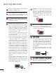
WATCHING TV / CHANNEL CONTROL Add/Delete Channel (Manual Tuning) If selecting DTV or CADTV input signal, you can view the on-screen signal strength monitor to see the quality of the signal being received. CHANNEL Move Enter Move WATCHING TV / CHANNEL CONTROL Auto Tuning Auto Tuning Manual Tuning Manual Tuning Channel Edit Channel Edit Enter DTV F G Select channel type and RF-channel number. Channel 2 DTV 2-1 Bad Normal Good Delete Close 1 Select C H A N N E L.
Channel Editing A custom list can be created by toggling each channel on or off with ENTER button. The channels in the Custom List are displayed in black and the channels deleted from the Custom List are displayed in gray. Once a channel is highlighted you can add or delete the channel by referring to the small window at the topright corner of the screen. Move Enter Auto Tuning Manual Tuning Channel Edit Add/Delete 1 MENU 2 Select C H A N N E L. ENTER Select C h a n n e l E d i t.
WATCHING TV / CHANNEL CONTROL INPUT LIST 19/22LG3** TV AV Component RGB-PC HDMI Cable AV1 AV2 Component1 26LG3** WATCHING TV / CHANNEL CONTROL Antenna 1 ENTER INPUT 19/22LG3**: TV Select the desired input source. AV HDMI 26LG3**: Component RGB-PC Antenna Cable AV1 AV2 Component1 HDMI3 HDMI2 HDMI1 RGB-PC Component2 ie) TV AV Component RGB-PC Q.MENU ■ ■ ■ ■ 48 A n t e n n a: Select it to watch over-the-air broadcasts.
INPUT LABEL You can set a label for each input source when it's not in use.
PICTURE CONTROL PICTURE SIZE (ASPECT RATIO) CONTROL This feature lets you choose the way an analog picture with a 4:3 aspect ratio is displayed on your TV. ■ RGB-PC input source use 4:3 or 16:9 aspect ratio. ! NOTE G PICTURE CONTROL If a fixed image is displayed on the screen for a long time, the image could become imprinted on the screen and remain visible. This phenomenon is common to all manufacturers and is not covered by warranty.