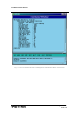
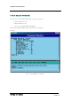
STAREX-IS BSM Manual Fig. 4.3-27 Forward Link Power Management Information (RS2) Verification SMD-011-PMA210 Page:199(877) Issue:1.
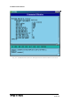
STAREX-IS BSM Manual 4.3.2.6. Backward Verification Link Power Management Information (RS2) Rate Set 2 transmits data at the speed of 14400,7200,3600,1800 bps. Input the following command to check the parameter information for RS2 Backward Link Power Management. Among the input values, FER (Frame Error Rate) has the value ranging from 0.5%, 1 to 5%.
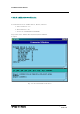
STAREX-IS BSM Manual Fig. 4.3-28 Backward Link Power Management Information (RS2) Verification SMD-011-PMA210 Page:201(877) Issue:1.
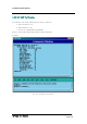
STAREX-IS BSM Manual 4.3.2.7. Service Option FER Verification Target FER can be designated by the Service Option. Input the following command to display this information.
STAREX-IS BSM Manual Fig. 4.3-29 Service Option FER Verification SMD-011-PMA210 Page:203(877) Issue:1.
STAREX-IS BSM Manual 4.3.2.8. MAHHO Verification • Command DIS-MAHH-PARA: BSC=a, BTS=b, SECT=c; a : BSC Number(0~11) b: BTS Number(0~47) c: Sector Id .(ALPHA/BETA/GAMMA) • Input DIS-MAHH-PARA: BSC=0,BTS=0,SECT=ALPHA; • Output Fig. 4.3-30 MAHHO Verification SMD-011-PMA210 Page:204(877) Issue:1.
STAREX-IS BSM Manual 4.3.2.9. LOCATION Verification • Command DIS-LOC-PARA: BSC=a, BTS=b, SECT=c; a : BSC Number(0~11) b: BTS Number(0~47) c: Sector Id .(ALPHA/BETA/GAMMA) • Input DIS-LOC-PARA: BSC=0,BTS=0,SECT=ALPHA; • Output Fig. 4.3-31 LOCATION Verification SMD-011-PMA210 Page:205(877) Issue:1.
STAREX-IS BSM Manual 4.3.2.10. SCH Verification • Command DIS-SCH-PARA: BSC=a, BTS=b, SECT=c; a : BSC Number(0~11) b: BTS Number(0~47) c: Sector Id .(ALPHA/BETA/GAMMA) • Input DIS-SCH-PARA: BSC=0,BTS=0,SECT=ALPHA; • Output Fig. 4.3-32 SCH Verification SMD-011-PMA210 Page:206(877) Issue:1.
STAREX-IS BSM Manual 4.3.2.11. Power Control Data Verification • Command DIS-PWR-CTRL: BSC=a, BTS=b, FER=c; a : BSC Number(0~11) b: BTS Number(0~47) c: FER (0~30) • Input DIS-PWR-CTRL: BSC=0, BTS=0,FER=0; • Output SMD-011-PMA210 Page:207(877) Issue:1.
STAREX-IS BSM Manual Fig. 4.3-33 Power Control Data Verification SMD-011-PMA210 Page:208(877) Issue:1.
STAREX-IS BSM Manual 4.3.2.12. BTS Name Display Input the following command to display the BTS name: • Command DIS-BTS-NAME: BSC=a, BTS=b; a : BSC Number(0~11) b: BTS Number(0~47) • Input DIS-BTS-NAME: BSC=0, BTS=0; • Output Fig. 4.3-34 BTS Name Display SMD-011-PMA210 Page:209(877) Issue:1.
STAREX-IS BSM Manual 4.3.2.13. PCP Timer Information Verification • Command DIS-PCF-TIMER:PCP =a; a : PCP Number(0~2) • Input DIS-PCF-TIMER: PCP=0; • Output Fig. 4.3-35 PCP Timer Information Verification SMD-011-PMA210 Page:210(877) Issue:1.
STAREX-IS BSM Manual 4.3.2.14. PCF Parameter Information Verification • Command DIS-PCF-PARA :PCP =a; a : PCP Number(0~2) • Input DIS-PCF-PARA: PCP=0; • Output Fig. 4.3-36 PCF Parameter Information Verification SMD-011-PMA210 Page:211(877) Issue:1.
STAREX-IS BSM Manual 4.3.2.15. PCF MAC ADDRESS Information Verification • Command DIS-PCF-MAC :PCP =a; a : PCP Number(0~2) • Input DIS-PCF-MAC: PCP=0; • Output Fig. 4.3-37 PCF MAC ADDRESS Information Verification SMD-011-PMA210 Page:212(877) Issue:1.
STAREX-IS BSM Manual 4.3.3. NETWORK Information Display (Display_Parameter_Information_3) 4.3.3.1. CAN ATM NODE Information Display • Command DIS-CAN-NODE; • Output SMD-011-PMA210 Page:213(877) Issue:1.
STAREX-IS BSM Manual Fig. 4.3-38 CAN ATM NODE Information Display SMD-011-PMA210 Page:214(877) Issue:1.
STAREX-IS BSM Manual 4.3.3.2. CAN PVC SETTING Information Display • Command • Input DIS-CAN-PVC;NODE_A=a; DIS-CAN-PVC: NODE_A=BSM_A; a: BSM_A,BSM_B, BSC (0~11) • Output Fig. 4.3-39 CAN PVC SETTING Information Display SMD-011-PMA210 Page:215(877) Issue:1.
STAREX-IS BSM Manual 4.3.3.3. CAN NETWORK PARAMETER Information Display • Command • Input DIS-CAN-NETP; DIS-CAN-NETP; • Output Fig. 4.3-40 CAN NETWORK PARAMETER Information Display SMD-011-PMA210 Page:216(877) Issue:1.
STAREX-IS BSM Manual 4.3.3.4. CAN INTER BSC AAL2 Setting Information Display • Command DIS-CAN-IUR:BSC=a; a:BSC Number (0~11) • Input DIS-CAN-IUR:BSC=0; • Output Fig. 4.3-41 CAN INTER BSC AAL2 Setting Information Display SMD-011-PMA210 Page:217(877) Issue:1.
STAREX-IS BSM Manual 4.3.3.5. CAN INTER BSC AAL5 Setting Information Display • Command DIS-CAN-BSC; • Output Fig. 4.3-42 CAN INTER BSC AAL5 Setting Information Display SMD-011-PMA210 Page:218(877) Issue:1.
STAREX-IS BSM Manual 4.3.3.6. CAN ATM NODE Information Display • Command DIS-CPN-NODE; • Output Fig. 4.3-43 CAN ATM NODE Information Display SMD-011-PMA210 Page:219(877) Issue:1.
STAREX-IS BSM Manual 4.3.3.7. PCF ATM NODE Information Display • Command DIS-PCF-NODE • Output Fig. 4.3-44 PCF ATM NODE Information Display SMD-011-PMA210 Page:220(877) Issue:1.
STAREX-IS BSM Manual 4.3.3.8. CAN PVC SETTING Information Display • Command DIS-CPN-PVC • Output Fig. 4.3-45 CAN PVC SETTING Information Display SMD-011-PMA210 Page:221(877) Issue:1.
STAREX-IS BSM Manual 4.3.3.9. CAN PCF PVC SETTING Information Display • Command DIS-PCF-PVC • Output Fig. 4.3-46 CAN PCF PVC SETTING Information Display SMD-011-PMA210 Page:222(877) Issue:1.
STAREX-IS BSM Manual 4.3.3.10. CPN METWORK PARAMETER Information Display • Command DIS-CPN-NETP • Output Fig. 4.3-47 CPN METWORK PARAMETER Information Display SMD-011-PMA210 Page:223(877) Issue:1.
STAREX-IS BSM Manual 4.3.3.11. CPN DATA AAL2/5 Connection Information Display • Command DIS-CPN-DATA; • Output Fig. 4.3-48 CPN DATA AAL2/5 Connection Information Display SMD-011-PMA210 Page:224(877) Issue:1.
STAREX-IS BSM Manual 4.3.3.12. CPN PCF AAK2/5 Connection Information Display • Command DIS-CPN-PCF; • Output Fig. 4.3-49 CPN PCF AAK2/5 Connection Information Display SMD-011-PMA210 Page:225(877) Issue:1.
STAREX-IS BSM Manual 4.3.3.13. BSC ATM NODE Information Display • Command DIS-BSC-NODE: BSC=a; a: BSC Number (0~11) • Input DIS-BSC-NODE: BSC=0; • Output Fig. 4.3-50 BSC ATM NODE Information Display SMD-011-PMA210 Page:226(877) Issue:1.
STAREX-IS BSM Manual 4.3.3.14. SLB ATM NODE Information Display • Command DIS-SLB-NODE: BSC=a; a: BSC Number (0~11) • Input DIS-SLB-NODE: BSC=0; • Output Fig. 4.3-51 SLB ATM NODE Information Display SMD-011-PMA210 Page:227(877) Issue:1.
STAREX-IS BSM Manual 4.3.3.15. VCB • Command ATM NODE Information Display DIS-VCB-NODE: BSC=a; a: BSC Number (0~11) • Input DIS-VCB-NODE: BSC=0; • Output Fig. 4.3-52 VCB SMD-011-PMA210 ATM NODE Information Display Page:228(877) Issue:1.
STAREX-IS BSM Manual 4.3.3.16. ALB ATM NODE Information Display ‘ • Command DIS-ALB-NODE: BSC=a; a: BSC Number (0~11) • Input DIS-ALB-NODE: BSC=0; • Output Fig. 4.3-53 ALB ATM NODE Information Display SMD-011-PMA210 Page:229(877) Issue:1.
STAREX-IS BSM Manual 4.3.3.17. BTS ATM NODE Information Display • Command DIS-BTS-NODE: BSC=a ,BTS=b; a: BSC Number (0~11) b: BTS Number (0~47) • Input DIS-BSC-NODE: BSC=0,BTS=0; • Output Fig. 4.3-54 BTS ATM NODE Information Display SMD-011-PMA210 Page:230(877) Issue:1.
STAREX-IS BSM Manual 4.3.3.18. BSC-BTS TRUNK Information Display • Command DIS-TRNK-DATA: BSC=a; a: BSC Number (0~11) • Input DIS-TRNK-DATA: BSC=0; • Output Fig. 4.3-55 BSC-BTS TRUNK Information Display SMD-011-PMA210 Page:231(877) Issue:1.
STAREX-IS BSM Manual 4.3.3.19. BSC PVC SETTING Information Display • Command DIS-BSC-PVC: BSC=a,NODE_A=b; a: BSC Number (0~11) b: NCP_A, NCP_B, CCP_A, CCP_B, ALMA0_0 , ALMA0_1, ALMA1_0 , ALMA1_1,CAN,CPN,ALP • Input DIS-BSC-PVC: BSC=0,NODE_A=NCP_A; • Output SMD-011-PMA210 Page:232(877) Issue:1.
STAREX-IS BSM Manual Fig. 4.3-56 BSC PVC SETTING Information Display SMD-011-PMA210 Page:233(877) Issue:1.
STAREX-IS BSM Manual 4.3.3.20. BSC SLB PVC SETTING Information Display • Command DIS-SLB-PVC: BSC=a; a: BSC Number (0~11) • Input DIS-SLB-PVC: BSC=0; • Output Fig. 4.3-57 BSC SLB PVC SETTING Information Display SMD-011-PMA210 Page:234(877) Issue:1.
STAREX-IS BSM Manual 4.3.3.21. BSC VCB PVC SETTING Information Display • Command DIS-VCB-PVC: BSC=a; a: BSC Number (0~11) • Input DIS-VCB-PVC: BSC=0; • Output Fig. 4.3-58 BSC VCB PVC SETTING Information Display SMD-011-PMA210 Page:235(877) Issue:1.
STAREX-IS BSM Manual 4.3.3.22. BSC ALB PVC SETTING Information Display • Command DIS-ALB-PVC: BSC=a; a: BSC Number (0~11) • Input DIS-ALB-PVC: BSC=0; • Output Fig. 4.3-59 BSC ALB PVC SETTING Information Display SMD-011-PMA210 Page:236(877) Issue:1.
STAREX-IS BSM Manual 4.3.3.23. BTS LOCAL PVC SETTING Information Display • Command DIS-BTS-LPVC: BSC=a; a: BSC Number (0~11) • Input DIS-BTS-LPVC: BSC=0; • Output Fig. 4.3-60 BTS LOCAL PVC SETTING Information Display SMD-011-PMA210 Page:237(877) Issue:1.
STAREX-IS BSM Manual 4.3.3.24. BTS OUTER PVC SETTING Information Display • Command DIS-BTS-OPVC: BSC=a, BTS=b; a: BSC Number (0~11) b: BTS Number(0~47) • Input DIS-BTS-OPVC: BSC=0, BTS=0; • Output Fig. 4.3-61 BTS OUTER PVC SETTING Information Display SMD-011-PMA210 Page:238(877) Issue:1.
STAREX-IS BSM Manual 4.3.3.25. BSC NETWORK PARAMETER Information Display • Command DIS-BSC-NETP: BSC=a; a: BSC Number (0~11) • Input DIS-BSC-NETP: BSC=0; • Output Fig. 4.3-62 BSC NETWORK PARAMETER Information Display SMD-011-PMA210 Page:239(877) Issue:1.
STAREX-IS BSM Manual 4.3.3.26. BSC ALP NETWORK PARAMETER Information Display • Command DIS-ALS-NETP: BSC=a; a: BSC Number (0~11) • Input DIS-ALS-NETP: BSC=0; • Output Fig. 4.3-63 BSC ALP NETWORK PARAMETER Information Display SMD-011-PMA210 Page:240(877) Issue:1.
STAREX-IS BSM Manual 4.3.3.27. BSC INTER BSC AAL2 Information Display • Command DIS-BSC-IUR: BSC=a; a: BSC Number (0~11) • Input DIS-BSC-IUR: BSC=0; • Output Fig. 4.3-64 BSC INTER BSC AAL2 Information Display SMD-011-PMA210 Page:241(877) Issue:1.
STAREX-IS BSM Manual 4.3.3.28. BSC INTER BTS AAL2 Information Display • Command DIS-BSC-IUB: BSC=a, BTS=b; a: BSC Number (0~11) b: BTS Number(0~47) • Input DIS-BSC-IUB: BSC=0, BTS=0; • Output Fig. 4.3-65 BSC INTER BTS AAL2 Information Display SMD-011-PMA210 Page:242(877) Issue:1.
STAREX-IS BSM Manual 4.3.3.29. BSC INTER CAN AAL2/5 Information Display • Command DIS-BSC-CAN: BSC=a; a: BSC Number (0~11) • Input DIS-BSC-CAN: BSC=0; • Output Fig. 4.3-66 BSC INTER CAN AAL2/5 Information Display SMD-011-PMA210 Page:243(877) Issue:1.
STAREX-IS BSM Manual 4.3.3.30. BSC INTER SLB AAL5 Information Display • Command DIS-BSC-SLB: BSC=a; a: BSC Number (0~11) • Input DIS-BSC-SLB: BSC=0; • Output’ Fig. 4.3-67 BSC INTER SLB AAL5 Information Display SMD-011-PMA210 Page:244(877) Issue:1.
STAREX-IS BSM Manual 4.3.3.31. BSC INTER VCB AAL5 Information Display • Command DIS-BSC-VCB: BSC=a; a: BSC Number (0~11) • Input DIS-BSC-VCB: BSC=0; • Output Fig. 4.3-68 BSC INTER VCB AAL5 Information Display SMD-011-PMA210 Page:245(877) Issue:1.
STAREX-IS BSM Manual 4.3.3.32. BSC INTER ALB AAL5 Information Display • Command DIS-BSC-ALB: BSC=a; a: BSC Number (0~11) • Input DIS-BSC-ALB: BSC=0; • Output Fig. 4.3-69 BSC INTER ALB AAL5 Information Display SMD-011-PMA210 Page:246(877) Issue:1.
STAREX-IS BSM Manual 4.3.3.33. BTS NETWORK PARAMETER Information Display • Command DIS-BTS-NETP: BSC=a ,BTS=b; a: BSC Number (0~11) b: BTS Number (0~47) • Input DIS-BTS-NETP: BSC=0,BTS=0; • Output Fig. 4.3-70 BTS NETWORK PARAMETER Information Display SMD-011-PMA210 Page:247(877) Issue:1.
STAREX-IS BSM Manual 4.3.3.34. BTS INTER BTS AAL2 Information Display • Command DIS-BTS-IUB: BSC=a ,BTS=b; a: BSC Number (0~11) b: BTS Number (0~47) • Input DIS-BTS-IUB: BSC=0,BTS=0; • Output Fig. 4.3-71 BTS INTER BTS AAL2 Information Display SMD-011-PMA210 Page:248(877) Issue:1.
STAREX-IS BSM Manual 4.3.3.35. BTS INTER RCU AAL5 Information Display • Command DIS-BTS-RCU: BSC=a ,BTS=b; a: BSC Number (0~11) b: BTS Number (0~47) • Input DIS-BTS-RCU: BSC=0,BTS=0; • Output Fig. 4.3-72 BTS INTER RCU AAL5 Information Display SMD-011-PMA210 Page:249(877) Issue:1.
STAREX-IS BSM Manual 4.3.4. Parameter Information Change Command (Change_Parameter_Information_1) This section describes commands that are used to change the parameter information that is inquired. The command to change parameter information cannot be easily input by the keyboard since input parameter counts are too many. For this reason, this section will skip the command input in Text and demonstrate window input by mouse.
STAREX-IS BSM Manual Table 4.
STAREX-IS BSM Manual 4.3.4.1. BTS Parameter Information Change To change the BTS parameter information, click CDM->Change_Parameter_ Information->Change BTS Data on the Command Window in order and input the value that the command wants to change in each field.
STAREX-IS BSM Manual Fig. 4.3-73 BTS Parameter Information Display 4.3.4.2. Sector Parameter Information Change To change the sector parameter information, click CDM->Change_Parameter_ Information_1-> CHG-SECT-DATA on the Command Window in order. If the next input window is displayed, then input the value to be changed. • Command CHG-SECT-DATA :BSC=a ,BTS=b ,SECT=c [,PN=d] [,CNTL_PARA=e] ; • Input CHG-SECT-DATA :BSC=0 ,BTS=0 ,SECT=ALPHA ,PN=40; • Output Fig. 4.
STAREX-IS BSM Manual 4.3.4.3. CDMA Channel Parameter Information Change To change the CDMA parameter information, click CDM->Change_Parameter_ Information_1-> CHG-CHAN-DATA on the Command Window in order. If the next input window is displayed, then input the value to be changed. • Command CHG-CHAN-DATA :BSC=a ,BTS=b ,CDMACH=c [,FREQ_BAND=d] [,CH_NUM=e] [,TCE_4HO=f] [,MAX_SCH=g]; • Input CHG-CHAN-DATA :BSC=0,BTS=0 ,CDMACH=0 ,FREQ_BAND=2222; • Output Fig. 4.
STAREX-IS BSM Manual 4.3.4.4. SYSTEM PARAMETER(1) Change To change the system parameter message, click CDM-> Change_Parameter_Information_1-> CHG-SYS1-PARA on the Command Window in order. As the System Parameter Message have many elements, they are divided into the three commands. The output format for each command is the same.
STAREX-IS BSM Manual Fig. 4.3-76 System Parameter Change(1) Display 4.3.4.5. SYSTEM 4.3.4.6. PARAMETER(2) Change To change the system parameter message, click CDM-> Change_Parameter_Information_1-> CHG-SYS2-PARA on the Command Window in order. Since the System Parameter Message have many elements, they are divided into three commands. The output format for each command is the same.
STAREX-IS BSM Manual Fig. 4.3-77 System Parameter Change(2) Display SMD-011-PMA210 Page:257(877) Issue:1.
STAREX-IS BSM Manual 4.3.4.7. EXTENDED SYSTEM PARAMETER(1) Change To change the Extended System Parameter Message, click CDM-> Change_Parameter_Information_1-> CHG-EXT1-SYS on the Command Window in order. If the next input window is displayed, then input the value to be changed.
STAREX-IS BSM Manual Fig. 4.3-78 Extended System Parameter Change(1) Display SMD-011-PMA210 Page:259(877) Issue:1.
STAREX-IS BSM Manual 4.3.4.8. EXTENDED SYSTEM PARAMETER(2) Change To change the Extended System Parameter Message, click CDM-> Change_Parameter_Information_1-> CHG-EXT2-SYS on the Command Window in order. If the next input window is displayed, then input the value to be changed.
STAREX-IS BSM Manual Fig. 4.3-79 Extended System Parameter Change(2) Display SMD-011-PMA210 Page:261(877) Issue:1.
STAREX-IS BSM Manual 4.3.4.9. Neighbor Cell Information Addition To add the neighbor list, click the CDM->Change_Parameter_Information_1-> ADDNGBR-DATA on the Command Window in order. If the next input window is displayed, then input the values to be changed.
STAREX-IS BSM Manual Fig. 4.3-80 Neighbor Cell Addition Display 4.3.4.10. Neighbor Cell Information Deletion To delete the neighbor list, click CDM->Change_Parameter_Information_1-> RMVNGBR-DATA on the Command Window in order. If the next window is displayed, then input the sector and PN value of the sector to be deleted. • Command • Input RMV-NGBR-DATA :BSC=a ,BTS=b ,SECT=c ,NGBR_PN=d; RMV-NGBR-DATA :BSC=0 ,BTS=0 ,SECT=ALPHA ,NGBR_PN=0; • Output Fig. 4.
STAREX-IS BSM Manual 4.3.4.11. Neighbor Cell Information Change To change the neighbor list, click CDM->Change_Parameter_Information_1-> CHGNGBR-DATA on the Command Window in order. If the next input Window is displayed, input the sector and the PN value of the sector to be deleted. • Command CHG-NGBR- DATA :BSC=a ,BTS=b ,SECT=c ,NGBR_PN=d ,NEW_INDEX=e • Input • Output SMD-011-PMA210 Page:264(877) Issue:1.
STAREX-IS BSM Manual 4.3.4.12. HOPPING BEACON PARAMETER Change To change Hopping Beacon Parameter, click CDM->Change_Parameter_Information_1> CHG-NGBR-BCON on the Command Window in order. • Command CHG-NGBR-BCON :BSC=a ,BTS=b ,SECT=c ,CDMACH=d [,NGBR_SRCH=e] [,USE_TIMING=f] [,G_TIME_INCL=g] [,G_TX_DURATE=h] [,G_TX_PERIOD=i] [,SRCH_OFF_INC=j] ; • Input CHG-NGBR-BCON :BSC=0 ,BTS=0 ,SECT=ALPHA ,CDMACH=0 , NGBR_SRCH=255; • Output Fig. 4.
STAREX-IS BSM Manual 4.3.4.13. QOS Parameter Change To change Quality Of Service parameter >Change_Parameter_Information_1-> CHG-QOS-PARA information, click CDM- on the Command Window in order. • Command CHG-QOS-PARA :BSC=a ,BTS=b [,MAX_SCH_RATE=c]; • Input CHG-QOS-PARA :BSC=0 ,BTS=0,MAX_SCH_RATE=255; • Output Fig. 4.3-83 QOS Parameter Information Change Display SMD-011-PMA210 Page:266(877) Issue:1.
STAREX-IS BSM Manual 4.3.4.14. Chip Power Control Information Change To change Chip Power Control information, click CDM- >Change_Parameter_Information_1-> CHG-CHIP-PWR on the Command Window in order.
STAREX-IS BSM Manual Fig. 4.3-84 Chip Power Control Information Change Display 4.3.4.15. TIC Parameter Change To change Tx Gain value, click CDM->Change_ Parameter_Information_1-> CHGTIC-DATA on the Command Window in order. If the next input window is displayed, then input the value to be changed. • Command CHG-TIC-DATA :BSC=a ,BTS=b ,SECT=c ,CDMACH=d [,TX_GAIN=e] ; • Input CHG-TIC-DATA :BSC=0 ,BTS=0 ,SECT=ALPHA ,CDMACH=0 ,TX_GAIN=255 ; • Output SMD-011-PMA210 Page:268(877) Issue:1.
STAREX-IS BSM Manual Fig. 4.3-85 TIC Parameter Information Change Display SMD-011-PMA210 Page:269(877) Issue:1.
STAREX-IS BSM Manual 4.3.4.16. OCNS Parameter Change To change OCNS Parameter value, click CDM->Change_ Parameter_Information_1-> CHG-OCNS-PARA on the Command Window in order. If the next input Window is displayed, then input the value to be changed. • Command CHG-OCNS-PARA :BSC=a ,BTS=b ,SECT=c ,CDMACH=d [,OCNS_ENABLE=e] [,NUM_OCNS_CH=f] [,OCNS_TEST=g] [,OCNS_SO=h]; • Input CHG-OCNS-PARA :BSC=0 ,BTS=0 ,SECT=ALPHA , CDMACH=0 ,OCNS_ENABLE=DISABLE,NUM_OCNS_CH=2; • Output Fig. 4.
STAREX-IS BSM Manual 4.3.4.17. Power Control Information Change To change OCNS Parameter value, click CDM->Change_ Parameter_Information_1-> CHG-PWR-PARA on the Command Window in order. If the next input Window is displayed, then input the value to be changed.
STAREX-IS BSM Manual Fig. 4.3-87 Power Control Parameter Information Display SMD-011-PMA210 Page:272(877) Issue:1.
STAREX-IS BSM Manual 4.3.4.18. ACCESS CHANNEL Parameter Information Change To change Access Channel Parameter information, click CDM-> Change_ Parameter_Information->CHG-AC-PARA on the Command Window in order. If the next input window is displayed, then input the value to be changed. • Command CHG-AC-PARA :BSC=a ,BTS=b ,SECT=c ,CDMACH=d ,PC=e ,AC=f [,SRCH_OFFSET=g] [,SRCH_WIN_SZ=h]; • Input CHG-AC-PARA :BSC=0 ,BTS=0 ,SECT=ALPHA , CDMACH=0 , PC=0, SRCH_WIN_SZ=32; • Output Fig. 4.
STAREX-IS BSM Manual 4.3.4.19. TXMS Parameter Information Change To change TXMS Parameter information, click CDM-> Change_ Parameter_Information->CHG-TXMS-PARA on the Command Window in order. If the next input window is displayed, then input the value to be changed. •Command CHG-TXMS- PARA :BSC=a ,BTS=b ,SECT=c ,CDMACH=d ,OH_CH_ERP=e ; • Input CHG-TXMS-PARA :BSC=0 ,BTS=0 ,SECT=ALPHA ,CDMACH=0 , OH_CH_ERP=25000 ; • Output Fig. 4.
STAREX-IS BSM Manual 4.3.4.20. BTS CALIBRATION Start To start BTS Calibration, click CDM-> Change_ Parameter_Information->STARTBTS-CALB on the Command Window in order. If the next input window is displayed, then input the value to be changed. • Command START-BTS-CALB [,CDMACH=d] ,METHOD=e :BSC=a ,BTS=b [,SECT=c] ; • Input START-BTS-CALB :BSC=0 ,BTS=0 ,SECT=ALPHA,METHOD=OVHD ; • Output Fig. 4.3-90 BTS Calibration Start Display SMD-011-PMA210 Page:275(877) Issue:1.
STAREX-IS BSM Manual 4.3.4.21. BTS Calibration Time Change To change BTS Calibration time, click CDM-> Change_ Parameter_Information->CHGCALB-TIME on the Command Window in order. If the next input window is displayed, then input the value to be changed. • Command CHG-CALB-DATA :BSC=a ,BTS=b ,HOUR=c ,MINUTE=d ,INTERVAL=e ,METHOD=f; • Input CHG-CALB-DATA :BSC=0 ,BTS=0 ,HOUR=1 ,MINUTE=1 ,INTERVAL=1 ,METHOD=OVHD; • Output Fig. 4.
STAREX-IS BSM Manual 4.3.4.22. PC GLOBAL REDIRECT Parameter Information Change To change Paging Channel Global Redirect information, click CDM-> Change_ Parameter_Information->CHG-GSRM-PARA on the Command Window in order. If the next input window is displayed, then input the value to be changed.
STAREX-IS BSM Manual Fig. 4.3-92 PC Global Redirect Parameter Information Change Display SMD-011-PMA210 Page:278(877) Issue:1.
STAREX-IS BSM Manual 4.3.4.23. ACCESS PARAMETER Change To change Access Parameter information, click CDM-> Change_ Parameter_Information->CHG-ACC-PARA on the Command Window in order. If the next input window is displayed, then input the value to be changed.
STAREX-IS BSM Manual Fig. 4.3-93 Access Parameter Information Change Display SMD-011-PMA210 Page:280(877) Issue:1.
STAREX-IS BSM Manual 4.3.4.24. PAGING CHANNEL Parameter Information Change To change Paging Channel Parameter information, click CDM-> Change_ Parameter_Information->CHG-PC-PARA on the Command Window in order. If the next input window is displayed, then input the value to be changed. • Command CHG-PC-PARA :BSC=a ,BTS=b ,SECT=c ,CDMACH=d ,PC=e [,PC_GAIN=f] [,FRM_DUR=g] [,DATA_RATE=h]; • Input CHG-PC-PARA :BSC=0 ,BTS=0 ,SECT=ALPHA ,CDMACH=0 ,PC=0 ,PC_GAIN=255; • Output Fig. 4.
STAREX-IS BSM Manual 4.3.4.25. PILOT CHANNEL Parameter Information Change To change Pilot Channel Parameter information, click CDM-> Change_ Parameter_Information->CHG-PICH-PARA on the Command Window in order. If the next input window is displayed, then input the value to be changed. • Command CHG-PICH-PARA :BSC=a ,BTS=b ,SECT=c ,CDMACH=d [,PLOT_GAIN=e] [,PLOT_TD_GAIN=f]; • Input CHG-PICH-PARA :BSC=0 ,BTS=0 ,SECT=ALPHA , CDMACH=0,PLOT_GAIN=255; • Output Fig. 4.
STAREX-IS BSM Manual 4.3.4.26. SYNC CHANNEL Parameter Information Change To change Sync. Channel Parameter information, click CDM-> Change_ Parameter_Information->CHG-SC-PARA on the Command Window in order. If the next input window is displayed, then input the value to be changed. • Command CHG-SC-PARA :BSC=a ,BTS=b ,SECT=c ,CDMACH=d [,SC_GAIN=e]; • Input CHG-SC-PARA :BSC=0 ,BTS=b ,SECT=ALPHA ,CDMACH=0,SC_GAIN=255; • Output Fig. 4.
STAREX-IS BSM Manual 4.3.4.27. QUICH PAGING CHANNEL Parameter Information Change To change Quick Paging Channel Parameter information, click CDM-> Change_ Parameter_Information->CHG-QPC-PARA on the Command Window in order. If the next input window is displayed, then input the value to be changed. • Command CHG-QPC-PARA :BSC=a ,BTS=b ,SECT=c ,CDMACH=d ,QPCH_ID=e [,FRAME_DUR=f] [,DATA_RATE=g]; • Input CHG-QPC-PARA :BSC=0 ,BTS=0 ,SECT=ALPHA ,CDMACH=0 ,QPCH_ID=0 ,FRAME_DUR=255; • Output Fig. 4.
STAREX-IS BSM Manual 4.3.4.28. HOPPING PILOT BEACON CHANNEL Parameter Information Change To change Hopping Pilot Beacon Channel Parameter information, click CDM-> Change_ Parameter_Information->CHG-BCON-PARA on the Command Window in order. If the next input window is displayed, then input the value to be changed.
STAREX-IS BSM Manual 4.3.4.29. CDMA Channel FA Test Start To start the CDMA Channel FA test, click CDM-> Change_ Parameter_Information>STRT-FA-TEST on the Command Window in order. If the next input window is displayed, then input the value to be changed. • Command STRT-FA-TEST :BSC=a ,BTS=b ,FA=c; • Input STRT-FA-TEST :BSC=0 ,BTS=0 ,FA=0; • Output Fig. 4.3-99 CDMA Channel FA Test Start Display 4.3.4.30.
STAREX-IS BSM Manual • Output Fig. 4.3-100 CDMA Channel FA Test Termination Display SMD-011-PMA210 Page:287(877) Issue:1.
STAREX-IS BSM Manual 4.3.5. Parameter Information Change Command (Change_Parameter_Information_2) This section describes commands that are used to change the parameter information that is inquired (required). The command to change parameter information cannot be easily input by the keyboard since input parameter counts are too many. For this reason, this section will skip the command input in text and demonstrate window input by mouse.
STAREX-IS BSM Manual 2266 CHG-PWR2-CTRL POWER CONTROL parameter information (2) change 2267 CHG-PWR3-CTRL POWER CONTROL parameter information (3) change 2271 CHG-BTS-NAME BTS name change 2292 CHG-PCF-TIMER PCF TIMER change 2294 CHG-PCP-ADDR PCP/PMP ADDRESS change 2295 CHG-PIP-ADDR PIP ADDRESS change 2296 CHG-PCF-PARA PCF PARAMETER change 4.3.5.1. Dormant Timer Change To change Dormant Timer, click CDM->Change_Parameter_ Information_2-> CHGDORM-DATA on the Command Window in order.
STAREX-IS BSM Manual Fig. 4.3-101 Dormant Timer Change Display 4.3.5.2. PACKET ZONE DATA Change To change PACKET ZONE DATA, click CDM->Change_Parameter_ Information_2-> CHG-PKZN-DATA on the Command Window in order. Input the value to be changed in each field as shown below. • Command CHG-PKZN-DATA :BSC=a [,PKT_ZONE=b] [,PCP_ID=c]; • Input CHG-PKZN-DATA :BSC=0,PKT_ZONE=255; • Output Fig. 4.3-102 Packet Zone Data Change Display SMD-011-PMA210 Page:290(877) Issue:1.
STAREX-IS BSM Manual 4.3.5.3. FACILITIES MANAGEMENT TIMER Change To change FACILITIES MANAGEMENT TIMER, click CDM->Change_Parameter_ Information_2-> CHG-FAC-TIMER on the Command Window in order. Input the value to be changed in each field as shown below. • Command CHG-FAC-TIMER :BSC=a [,T1=b] [,T2=c] [,T4=d] [,T5=e] [,T6=f] [,T12=g] [,T13=h] [,T16=i] [,T309=j]; • Input CHG-FAC-TIMER :BSC=0,T1=255; • Output Fig. 4.3-103 Facilities Management Timer Change Display SMD-011-PMA210 Page:291(877) Issue:1.
STAREX-IS BSM Manual 4.3.5.4. HANDOFF TIMER Change To change HANDOFF TIMER, click CDM->Change_Parameter_ Information_2-> CHGHO-TIMER on the Command Window in order. Input the value to be changed in each field as shown below. • Command CHG-HO-TIMER :BSC=a [,T7=b] [,T9=c] [,T10=d] [,T50=e] [,T52=f] [,T777=g] [,T778=h] [,T787=i] [,T789=j] [,T790=k]; • Input CHG-HO-TIMER :BSC=0,T7=255; • Output FIG 4.3-104 SMD-011-PMA210 Handoff Timer Change Display Page:292(877) Issue:1.
STAREX-IS BSM Manual 4.3.5.5. BSC SUPPLEMENT SERVICES TIMER Change To change BSC SUPPLEMENT SERVICES TIMER, click CDM->Change_Parameter_ Information_2-> CHG-SUP-TIMER on the Command Window in order. Input the value to be changed in each field as shown below. • Command CHG-SUP-TIMER :BSC=a [,T60=b] [,T61=c] [,T62=d] [,T63=e] ; • Input CHG-SUP-TIMER :BSC=0,T60=99; • Output Fig. 4.3-105 BSC Supplement Services Timer Change Display SMD-011-PMA210 Page:293(877) Issue:1.
STAREX-IS BSM Manual 4.3.5.6. BSC CALL PROCESSING TIMER Change To change BSC CALL PROCESSING TIMER, click CDM->Change_Parameter_ Information_2-> CHG-CALL-TIMER on the Command Window in order. Input the value to be changed in each field as shown below.
STAREX-IS BSM Manual 4.3.5.7. BSC MOBILITY MANAGEMENT TIMER Change To change BSC MOBILITY MANAGEMENT TIMER, click CDM->Change_Parameter_ Information_2-> CHG-MOB-TIMER on the Command Window in order. Input the value to be changed in each field as shown below. • Command CHG-MOB-TIMER :BSC=a [,T3210=b] [,T3220=c] [,T3240=d] [,T3260=e] [,T3270=f] [,T3271=g] [,T3272=h]; • Input CHG-MOB-TIMER :BSC=0,T3210=99; • Output Fig. 4.
STAREX-IS BSM Manual 4.3.5.8. A8 A9 INTERFACE TIMER Change To change A8 A9 INTERFACE TIMER, click CDM->Change_Parameter_ Information_2_2-> CHG-A89-TIMER on the Command Window in order. Input the value to be changed in each field as shown below. • Command CHG-A89-TIMER :BSC=a [,TA8_SETUP=b] [,Talc9=c] [,Tald9=d] [,Trel9=e]; • Input CHG-A89-TIMER :BSC=0,TA8_SETUP=99; • Output Fig. 4.3-108 A8 A9 INTERFACE TIMER Change SMD-011-PMA210 Page:296(877) Issue:1.
STAREX-IS BSM Manual 4.3.5.9. A3, A7 INTERFACE TIMER Change To change A3 A7 INTERFACE TIMER, click CDM->Change_Parameter_ Information_2_2-> CHG-A37-TIMER on the Command Window in order. Input the value to be changed in each field as shown below. • Command CHG-A37-TIMER :BSC=a [,Tacm=b] [,Tbstact=c] [,Tbsccom=d] [,Tchanstat=e] [,Tconn3=f] [,Tdiscon3=g] [,Tdrptgt=h] [,Ttgtrmv=i] [,Thoreq=j] [,Tpcm=k] [,Tphysical=l]; • Input CHG-A37-TIMER :BSC=0,Tacm=1000; • Output Fig. 4.
STAREX-IS BSM Manual 4.3.5.10. Forward Link Power Management Information (RS1) Change To change forward link power management information (RS1), click CDM- >Change_Parameter_ Information_2_2-> CHG-RS1-FWDP on the Command Window in order. Input the value to be changed in each field as shown below.
STAREX-IS BSM Manual Fig. 4.3-110 Forward Link Power Management Information (RS1) Change 4.3.5.11. Backward Link Power Management Information (RS1) Change To change Backward link power management information (RS1), click CDM>Change_Parameter_ Information_2_2-> CHG-RS1-REVP on the Command Window in order. Input the value to be changed in each field as shown below.
STAREX-IS BSM Manual 4.3.5.12. Forward Link Power Management Information (RS2) Change To change Forward link power management information (RS2), click CDM>Change_Parameter_ Information_2_2-> CHG-RS2-FWDP on the Command Window in order. Input the value to be changed in each field as shown below.
STAREX-IS BSM Manual Fig. 4.3-112 Forward Link Power Management Information (RS2) Change 4.3.5.13. Backward Link Power Management Information (RS2) Change To change Backward link power management information (RS2), click CDM>Change_Parameter_ Information_2_2-> CHG-RS2-REVP on the Command Window in order. Input the value to be changed in each field as shown below.
STAREX-IS BSM Manual Fig. 4.3-113 Backward Link Power Management Information (RS2) Change SMD-011-PMA210 Page:302(877) Issue:1.
STAREX-IS BSM Manual 4.3.5.14. Service Option FER Change To change Service Option FER, click CDM->Change_Parameter_ Information_2_2-> CHG-FER-PARA on the Command Window in order. Input the value to be changed in each field as shown below.
STAREX-IS BSM Manual Fig. 4.3-114 Service Option FER Change SMD-011-PMA210 Page:304(877) Issue:1.
STAREX-IS BSM Manual 4.3.5.15. MAHHO DATA Change To change MAHHO DATA, click the CDM->Change_Parameter_ Information_2-> CHG-MAHO-DATA on the Command Window in order. Input the value to be changed in each file as shown below.
STAREX-IS BSM Manual Fig. 4.3-115 MAHHO DATA Change SMD-011-PMA210 Page:306(877) Issue:1.
STAREX-IS BSM Manual 4.3.5.16. LOCATION PARA Information Change To change LOCATION PARA information, click CDM->Change_Parameter_ Information_2-> CHG-LOC-PARA on the Command Window in order. Input the value to be changed in each field as shown below.
STAREX-IS BSM Manual 4.3.5.17. SCH Parameter Information Change To change SCH PARA information, click CDM->Change_Parameter_ Information_2-> CHG-SCH-PARA on the Command Window in order. Input the value to be changed in each field as shown below.
STAREX-IS BSM Manual 4.3.5.18. POWER CONTROL Parameter Information (1) Change To change POWER CONTROL Parameter information (1), click CDM- >Change_Parameter_ Information_2-> CHG-PWR1-CTRL on the Command Window in order. Input the value to be changed in each field as shown below.
STAREX-IS BSM Manual Fig. 4.3-118 POWER CONTROL Parameter Information (1) Change SMD-011-PMA210 Page:310(877) Issue:1.
STAREX-IS BSM Manual 4.3.5.19. POWER CONTROL Parameter Information (2) Change To change POWER CONTROL Parameter information (2), click CDM- >Change_Parameter_ Information_2-> CHG-PWR2-CTRL on the Command Window in order. Input the value to be changed in each field as shown below.
STAREX-IS BSM Manual 4.3.5.20. POWER CONTROL Parameter Information (3) Change To change POWER CONTROL Parameter information (3), click CDM- >Change_Parameter_ Information_2-> CHG-PWR3-CTRL on the Command Window in order. Input the value to be changed in each field as shown below.
STAREX-IS BSM Manual 4.3.5.21. BTS Name Change To change BTS name, click CDM->Change_Parameter_ Information_2-> CHG-BTSNAME on the Command Window in order. Input the value to be changed in each field as shown below. • Command CHG-BTS-NAME :BSC=a ,BTS=b ,NAME=c; • Input CHG-BTS-NAME :BSC=0 ,BTS=0 ,NAME=jhpark; • Output Fig. 4.3-121 BTS Name Change SMD-011-PMA210 Page:313(877) Issue:1.
STAREX-IS BSM Manual 4.3.5.22. PCF TIMER Change To change PCF TIMER, click CDM->Change_Parameter_ Information_2-> CHG-PCFTIMER on the Command Window in order. Input the value to be changed in each field as shown below. • Command CHG-PCF-TIMER :PCP=a [,TRP_LIFETIME=b] [,TBSREQ9=c] [,TDISCON9=d] [,TWAITHO9=e] [,TREGREQ=f] [,RRQ_RETRY_CNT=g]; • Input CHG-PCF-TIMER :PCP=0,TRP_LIFETIME=255; • Output Fig. 4.3-122 PCF TIMER Change SMD-011-PMA210 Page:314(877) Issue:1.
STAREX-IS BSM Manual 4.3.5.23. PCP/PMP ADDRESS Change To change PCP/PMP ADDRESS, click CDM->Change_Parameter_ Information_2-> CHG-PCP-ADDR on the Command Window in order. Input the value to be changed in each field as shown below. • Command CHG-PCP-ADDR :PCF=a ,SHELF_ID=b ,SIDE=c ,IP_ADDR=d; • Input CHG-PCP-ADDR :PCF=0 ,SHELF_ID=0 ,SIDE=A_SIDE , IP_ADDR=255.255.255.255; • Output Fig. 4.3-123 PCP/PMP ADDRESS Change SMD-011-PMA210 Page:315(877) Issue:1.
STAREX-IS BSM Manual 4.3.5.24. PIP ADDRESS Change To change PIP ADDRESS, click CDM->Change_Parameter_ Information_2-> CHGPIP-ADDR on the Command Window in order. Input the value to be changed in each field as shown below. • Command CHG-PIP-ADDR :PCF=a ,SHELF_ID=b ,PIP_ID=c [,IP_ADDR=d] [,NETMASK=e] • Input CHG-PIP-ADDR :PCF=0 ,SHELF_ID=0 ,PIP_ID=0, NETMASK=255.255.0.0; • Output Fig. 4.3-124 PIP ADDRESS Change SMD-011-PMA210 Page:316(877) Issue:1.
STAREX-IS BSM Manual 4.3.5.25. PCF PARAMETER Change To change PCF PARAMETER, click CDM->Change_Parameter_ Information_2-> CHGPCF-PARA on the Command Window in order. Input the value to be changed in each field as shown below. • Command CHG-PCF-PARA :PCF=a [,AAA_TYPE=b] [,SID=c] [,NID=d] [,LTM_OFF=e] [,DAY_LT=f] [,PKZN_ID=g] [,ID_TYPE=h] [,GRE_SEQ=i] [,SEQ_TIMER=j] [,MSID_TYPE=k]; • Input CHG-PCF-PARA :PCF=0,AAA_TYPE=255,SEQ_TIMER=255; • Output Fig. 4.
STAREX-IS BSM Manual 4.3.6. Network Parameter Information Change (Change_Parameter_Info_3) 4.3.6.1. CAN INTER BSC AAL2 Setting Information Change • Command CHG-CAN-IUR: BSC=a, [BSC0_AAL2=b], [BSC1_AAL2=c], [BSC2_AAL2=d], [BSC3_AAL2=e], [BSC4_AAL2=f], [BSC5_AAL2=g], [BSC6_AAL2=h], [BSC7_AAL2=i], [BSC8_AAL2=j],[BSC9_AAL2=k],[BSC10_AAL2=l], [BSC11_AAL2=m], [NO_AAL2_VC=n]; • Input CHG-CAN-IUR: BSC=0, BSC0_AAL2=255 • Output SMD-011-PMA210 Page:318(877) Issue:1.
STAREX-IS BSM Manual 4.3.6.2. CAN INTER BSC AAL5 Setting Information Change • Command CHG-CAN-BSC: [CAN0_START_AAL5=a], [CAN1_START_AAL5=b], [NO_AAL5_VC=0~], a ,b: 0~0xffffff c: 0~ • Input CHG-CAN-BSC: CAN0_START_AAL5=255 • Output SMD-011-PMA210 Page:319(877) Issue:1.
STAREX-IS BSM Manual 4.3.6.3. CPN INTER DATA AAL5 Setting Information Change • Command CHG-CPN-DATA: [BSC0_AAL5=a], [BSC1_AAL5=b], [BSC2_AAL5=c], [BSC3_AAL5=d], [BSC4_AAL5=e], [BSC5_AAL5=f], [BSC6_AAL5=g], [BSC7_AAL5=h], [BSC8_AAL5=i], [BSC9_AAL5=j], [BSC10_AAL5=k], [BSC11_AAL5=l], [NO_AAL5_VC=m]; a ~n: BSC AAL5 (32~0xffffff) m: 0~32 • Input CHG-CPN-DATA: BSC0_AAL5=255; • Output SMD-011-PMA210 Page:320(877) Issue:1.
STAREX-IS BSM Manual 4.3.6.4.
STAREX-IS BSM Manual 4.3.6.5. BSC INTER BSC AAL2 Setting Information Change • Command CHG-BSC-IUR: BSC=a, [BSC0_AAL2=b], [BSC1_AAL2=c], [BSC2_AAL2=d], [BSC3_AAL2=e], [BSC4_AAL2=f], [BSC5_AAL2=g], [BSC6_AAL2=h], [BSC7_AAL2=i], [BSC8_AAL2=j], [BSC9_AAL2=k], [BSC10_AAL2=l], [BSC11_AAL2=m], [NO_AAL2_VC=n]; a : BSC Number(0~11) b~m: BSC AAL2 (0~0xffffff) n: 0~ • Input CHG-BSC-IUR: BSC=0, BSC0_AAL2=255; • Output SMD-011-PMA210 Page:322(877) Issue:1.
STAREX-IS BSM Manual 4.3.6.6.
STAREX-IS BSM Manual 4.3.6.7. BSC INTER CAN AAL2/5 Setting Information Change • Command CHG-BSC-CAN: BSC=a, [CAN0_START_AAL5=b], [CAN1_START_AAL5=c], [NO_AAL5_VC=d] a: BSC Number(0~11) b,c: 32~0xffffff d: 0~8160 • Input CHG-BSC-CAN: BSC=0, CAN0_START_AAL5=255; • Output SMD-011-PMA210 Page:324(877) Issue:1.
STAREX-IS BSM Manual 4.3.6.8.
STAREX-IS BSM Manual 4.3.6.9. BSC INTER VCB AAL5 Setting Information Change • Command CHG-BSC-VCB: BSC=a, [VCP0_AAL5=b], [VCP1_AAL5=c], [VCP2_AAL5=d], [VCP3_AAL5=e], [VCP4_AAL5=f], [VCP5_AAL5=g], [VCP6_AAL5=h], [VCP7_AAL5=i], [VCP8_AAL5=j], [VCP9_AAL5=k], [VCP10_AAL5=l], [VCP11_AAL5=m], [VCP12_AAL5=n], [VCP13_AAL5=o], [VCP14_AAL5=p], [VCP15_AAL5=q], [NO_AAL5_VC=r] a: BSC Number(0~11) b~q: 40~0xffffff r: 0~88 • Input CHG-BSC-VCB: BSC=0, VCP0_AAL5=255; • Output SMD-011-PMA210 Page:326(877) Issue:1.
STAREX-IS BSM Manual 4.3.6.10.
STAREX-IS BSM Manual 4.3.6.11. BTS INTER RCU AAL5 Setting Information Change • Command CHG-BTS-RCU: BSC=a, BTS=b, RCU=c, [LICA0_AAL5=d], [LICA1_AAL5=e], [LICA2_AAL5=f], [LICA0_NO_VC=g], [LICA1_NO_VC=h], [LICA2_NO_VC=i] a: BSC Number(0~11) b:BTS Number(0~47) c: RCU Number(0~9) d~i: 0~ • Input CHG-BTS-RCU: BSC=0,BTS=0,RCU=0, LICA0_AAL5=255; • Output SMD-011-PMA210 Page:328(877) Issue:1.
STAREX-IS BSM Manual 4.3.7. Configuration Information Display(Display_Configuration_Data) This section describes the comands that are used to inquire the configuration information which is related to processors, devices, and overhead channels which are currently used in BTS and BSC. Table 4.
STAREX-IS BSM Manual 4.3.7.1. BSS Configuration Information Verification This is a command to check the BTS, Processors and PCF counts in the BSC. • Command DIS-BSS-CONF: BSC=a; • Input DIS-BSS-CONF: BSC=0; • Output Fig. 4.3-126 BSS Configuration Information Display SMD-011-PMA210 Page:330(877) Issue:1.
STAREX-IS BSM Manual 4.3.7.2. SMP Configuration Information Verification • Command DIS-SMP-CONF: BSC=a; a: BSC Number(#0~11) • Input DIS-SMP-CONF: BSC=0; • Output Fig. 4.3-127 SMP Configuration Information Display SMD-011-PMA210 Page:331(877) Issue:1.
STAREX-IS BSM Manual 4.3.7.3. VMP Configuration Information Verification • Command DIS-VMP-CONF: BSC=a; a: BSC Number(#0~11) • Input DIS-VMP-CONF: BSC=0; • Output Fig. 4.3-128 VMP Configuration Information Display SMD-011-PMA210 Page:332(877) Issue:1.
STAREX-IS BSM Manual 4.3.7.4. BTS Configuration Information Verification • Command DIS-BTS-CONF: BSC=a, BTS=b; a: BSC Number(#0~11) b: BTS Number(#0~47) • Input DIS-BTS-CONF: BSC=0, BTS=0; • Output Fig. 4.3-129 BTS Configuration Information Display SMD-011-PMA210 Page:333(877) Issue:1.
STAREX-IS BSM Manual 4.3.7.5. DBPA CHIP Configuration Information Verification • Command DIS-CHIP-CONF: BSC=a, BTS=b; a: BSC Number(#0~11) b: BTS Number(#0~47) • Input DIS-CHIP-CONF: BSC=0, BTS=0; • Output Fig. 4.3-130 DBPA CHIP Configuration Information Display SMD-011-PMA210 Page:334(877) Issue:1.
STAREX-IS BSM Manual 4.3.7.6. OVERHEAD CHANNEL Configuration Information Verification • Command DIS-OVHD-CONF: BSC=a, BTS=b; a: BSC Number(#0~11) b: BTS Number(#0~47) • Input DIS-OVHD-CONF: BSC=0, BTS=0; • Output Fig. 4.3-131 OVHD Channel Configuration Information Display SMD-011-PMA210 Page:335(877) Issue:1.
STAREX-IS BSM Manual 4.3.7.7. PDSN Configuration Information Verification • Command DIS-PDSN-CONF: PCP=a; a: PCP Number(#0~2) • Input DIS-PDSN-CONF: PCP=0; • Output Fig. 4.3-132 PDSN Configuration Information Display SMD-011-PMA210 Page:336(877) Issue:1.
STAREX-IS BSM Manual 4.3.8. Configuration Information Change (Change_Configuration_Data) This section describes commands that are used to add or delete BTS and BSC processors and devices. The configuration information that can be added and deleted are presented below. For the command that has many parameters to input, input image on the inpout Widow. This section does not cover details of each parameter. Table 4.
STAREX-IS BSM Manual C2721 ADD-SMP-CONF SMP configuration addition C2722 RMV-SMP-CONF SMP configuration deletion C2731 ADD-VMP-CONF VMP configuration addition C2732 RMV-VMP-CONF VMP configuration deletion C2741 ADD-BTS-CONF BTS configuration addition C2742 RMV-BTS-CONF BTS configuration deletion C2751 ADD-SECT-CONF SECTOR configuration addition C2752 RMV-SECT-CONF SECTOR configuration deletion C2761 ADD-FA-CONF FA configuration addition C2762 RMV-FA-CONF FA configuration deleti
STAREX-IS BSM Manual 4.3.8.1. BTS Configuration Information Change • Command CHG-BTS-CONF :BSC=a ,BTS=b [,PA_TYPE=c] [,ANT_TYPE=d] [,ANT_DUP=e] [,RX_DIV=f] [,LNA_EQP=g] [,RISA_EQP=h] [,BOTA_EQP=i]; • Input CHG-BTS-CONF: BSC=0, BTS=0,PA_TYPE=FA_NEQ; • Output Fig. 4.3-133 BTS Configuration Information Change Display SMD-011-PMA210 Page:339(877) Issue:1.
STAREX-IS BSM Manual 4.3.8.2.
STAREX-IS BSM Manual • Input CHG-CHIP1-CONF:BSC=0, BTS=0,SECT_GAIN_A=255; • Output Fig. 4.3-134 Channel Card Chip Configuration Information (1) Change Display SMD-011-PMA210 Page:341(877) Issue:1.
STAREX-IS BSM Manual 4.3.8.3. Channel Card Chip Configuration Information (2) Change • Command CHG-CHIP2-CONF :BSC=a ,BTS=b [,NUM_CHIP=c] [,SECT_T_IO=d] [,CELL_RADIUS=e] [,MAX_RACH_F=h] [,MAX_REACH_S=k] [,REV_IN_FORM=f] [,R_CELL_MODE=g] [,MAX_RACH_S=i] [,SRCH_WIN_ADJ=l] [,MAX_CDMA2K=n] [,CSM_MODE=o] SMD-011-PMA210 [,MAX_REACH_F=j] [,MAX_CH95=m] [,DIV_SCALE_2K=p]; Page:342(877) Issue:1.
STAREX-IS BSM Manual • Input CHG-CHIP2-CONF: BSC=0, BTS=0,NUM_CHIP=255; • Output Fig. 4.3-135 Channel Card Chip Configuration Information (2) Change Display SMD-011-PMA210 Page:343(877) Issue:1.
STAREX-IS BSM Manual 4.3.8.4. PDSN CONFIG Addition • Command ADD-PDSN-CONF :PCF=a ,PDSN_IDX=b ,PDSN_IP=c; • Input ADD-PDSN-CONF: BSC=0, BTS=0,PDSN_IP=255.255.255.0; • Output Fig. 4.3-136 SMD-011-PMA210 PDSN Configuration Addition Display Page:344(877) Issue:1.
STAREX-IS BSM Manual 4.3.8.5. PDSN CONFIG Deletion • Command RMV-PDSN-CONF :PCF=a ,PDSN_IDX=b; • Input RMV-PDSN-CONF: BSC=0, BTS=0,PDSN_IDX=1; • Output Fig. 4.3-137 SMD-011-PMA210 PDSN Configuration Deletion Display Page:345(877) Issue:1.
STAREX-IS BSM Manual 4.3.8.6. PDSN CONFIG Change • Command CHG-PDSN-CONF :PCF=a ,PDSN_IDX=b ,PDSN_IP=c; • Input CHG-PDSN-CONF: BSC=0, BTS=0,PDSN_IP=127.0.0.1; • Output Fig. 4.3-138 SMD-011-PMA210 PDSN Configuration Change Display Page:346(877) Issue:1.
STAREX-IS BSM Manual 4.3.8.7. PDSN NODE Addition • Command ADD-PDSN-NODE :PCF=a ,PDSN_IDX=b ,PDSN_NODE_IDX=c , PDSN_NODE_IP=d ,SSK_VALUE=e • Input ADD-PDSN-NODE: BSC=0, BTS=0,PDSN_NODE_IDX=0, PDSN_NODE_IP:128.128.128.128; • Output Fig. 4.3-139 SMD-011-PMA210 PDSN NODE Addition Display Page:347(877) Issue:1.
STAREX-IS BSM Manual 4.3.8.8. PDSN NODE Deletion • Command RMV-PDSN-NODE :PCF=a ,PDSN_IDX=b ,PDSN_NODE_IDX=c; • Input RMV-PDSN-NODE: BSC=0, BTS=0,PDSN_IDX=0,PDSN_NODE_IDX=0; • Output Fig. 4.3-140 SMD-011-PMA210 PDSN NODE Deletion Display Page:348(877) Issue:1.
STAREX-IS BSM Manual 4.3.8.9. PDSN NODE Change • Command CHG-PDSN-NODE :PCF=a ,PDSN_IDX=b ,PDSN_NODE_IDX=c [,PDSN_NODE_IP=d] [,SSK_VALUE=e] • Input CHG-PDSN-NODE: BSC=0, BTS=0,PDSN_IDX=0,PDSN_NODE_IDX=0, PDSN_NODE_IP=100.100.0.1, SSK_VALUE=gamdok; • Output Fig. 4.3-141 SMD-011-PMA210 PDSN NODE Change Display Page:349(877) Issue:1.
STAREX-IS BSM Manual 4.3.8.10. BSC Node Movement • Command MOV-BSC-NODE :T_PROC=a ,BSC=b ,CARD=c ,LINK=d; • Input MOV-BSC-NODE: T_PROC=CNP,BSC=0,CARD=1,LINK=6;; • Output Fig. 4.3-142 SMD-011-PMA210 BSC NODE Movement Display Page:350(877) Issue:1.
STAREX-IS BSM Manual 4.3.8.11. PCF Node Movement • Command MOV-PCF-NODE :PCF=a ,CARD0=b ,LINK0=c ,CARD1=d ,LINK1=e ,CARD2=f ,LINK2=g ,CARD3=h ,LINK3=i; • Input MOV-PCF-NODE: BSC=0, BTS=0,PA_TYPE=FA_NEQ; • Output SMD-011-PMA210 Page:351(877) Issue:1.
STAREX-IS BSM Manual 4.3.8.12. SMP Node Movement • Command MOV-SMP-NODE :BSC=a ,SMP=b ,CARD=c ,LINK=d; • Input MOV-SMP-NODE: BSC=0, SMP=0,CARD=1,LINK=6 • Output Fig. 4.3-143 SMD-011-PMA210 SMP NODE Movement Display Page:352(877) Issue:1.
STAREX-IS BSM Manual 4.3.8.13. VMP Node Movement • Command MOV-VMP-NODE :BSC=a ,VMP=b ,CARD=c ,LINK=d; • Input MOV-VMP-NODE: BSC=0, VMP=0, CARD=1, LINK=6; • Output Fig. 4.3-144 SMD-011-PMA210 VMP NODE Movement Display Page:353(877) Issue:1.
STAREX-IS BSM Manual 4.3.8.14. BTS ID Movement • Command MOV-BTS-ID :BSC=a ,OLD_BTS=b ,NEW_BTS=c; • Input MOV-BTS-ID: BSC=0, OLD_BTS=0,NEW_BTS=2; • Output Fig. 4.3-145 SMD-011-PMA210 BTS ID Movement Display Page:354(877) Issue:1.
STAREX-IS BSM Manual 4.3.8.15. BTS TRUNK Node Movement For this command, execute DIS-TRNK-DATA first to input the parameter value. • Command MOV-BTS-TRNK :BSC=a ,BTS=b ,OLD_ALMA=c ,OLD_ALPA=d , OLD_ALPA_LINK=e ,NEW_ALMA=f ,NEW_ALPA=g ,NEW_ALPA_LINK=h; • Input MOV-BTS-TRNK: BSC=0, BTS=2, OLD_ALMA=0,OLD_ALPA=0,OLD_ALPA_LINK=0, NEW_ALMA=1,NEW_ALPA=1,NEW_ALPA_LINK=1; • Output Fig. 4.3-146 SMD-011-PMA210 BTS TRUNK Movement display Page:355(877) Issue:1.
STAREX-IS BSM Manual 4.3.8.16. LICA LINK Movement • Command MOV-LICA- LINK :BSC=a ,BTS=b ,OLD_LICA=c ,OLD_LINK=d ,NEW_LICA=e ,NEW_LINK=f; • Input MOV-LICA-LINK: BSC=0, BTS=1, OLD_LICA=0, OLD_LINK=0, NEW_LICA=1, NEW_LINK=1; • Output Fig. 4.3-147 SMD-011-PMA210 LICA LINK Movement Display Page:356(877) Issue:1.
STAREX-IS BSM Manual 4.3.8.17. OVERHEAD CHANNEL Configuration Information Movement Refer to DIS-OVHD-CONF command • Command MOV-OVHD-CONF :BSC=a ,BTS=b ,SECT=c ,CDMACH=d , NEW_CHC=e ; • Input MOV-OVHD-CONF: BSC=0, BTS=0, SECTOR=ALPHA,CDMACH=0,NEW_CHC=1; • Output Fig. 4.3-148 OVHD Channel Configuration Information Movement Display SMD-011-PMA210 Page:357(877) Issue:1.
STAREX-IS BSM Manual 4.3.8.18. BSC Configuration Addition • Command ADD-BSC-CONF :T_PROC=a ,BSC=b ,CARD=c ,LINK=d; • Input ADD-BSC-CONF: BSC=0, BTS=0,PA_TYPE=FA_NEQ; • Output SMD-011-PMA210 Page:358(877) Issue:1.
STAREX-IS BSM Manual 4.3.8.19. BSC Configuration Deletion • Command RMV-BSC-CONF :T_PROC=a ,BSC=b; • Input RMV-BSC-CONF: BSC=0, BTS=0,PA_TYPE=FA_NEQ; • Output SMD-011-PMA210 Page:359(877) Issue:1.
STAREX-IS BSM Manual 4.3.8.20. PCF Configuration Addition • Command ADD-PCF-CONF :PCF=a ,CARD0=b ,LINK0=c ,CARD1=d ,LINK1=e ,CARD2=f ,LINK2=g ,CARD3=h ,LINK3=i; • Input ADD-PCF- CONF:PCF=1,CARD0=3,LINK0=4,CARD1=3,LINK1=4,CARD2=3,LINK2=4,CARD3=3,LI NK3=4; • Output Fig. 4.3-149 SMD-011-PMA210 PCF Configuration Addition Display Page:360(877) Issue:1.
STAREX-IS BSM Manual 4.3.8.21. PCF Configuration Deletion • Command RMV-PCF-CONF :PCF=a; • Input RMV-PCF-CONF: PCF=1; • Output Fig. 4.3-150 SMD-011-PMA210 PCF Configuration Deletion Display Page:361(877) Issue:1.
STAREX-IS BSM Manual 4.3.8.22. SMP Configuration Addition • Command ADD-SMP-CONF :BSC=a ,SMP=b ,CARD=c ,LINK=d; • Input ADD-SMP-CONF: BSC=0,SMP=0,CARD=1,LINK=7; • Output Fig. 4.3-151 SMD-011-PMA210 SMP Configuration Addition Display Page:362(877) Issue:1.
STAREX-IS BSM Manual 4.3.8.23. SMP Configuration Deletion • Command RMV-SMP-CONF :BSC=a ,SMP=b; • Input RMV-SMP-CONF: BSC=0, SMP=0; • Output Fig. 4.3-152 SMD-011-PMA210 SMP Configuration Deletion Display Page:363(877) Issue:1.
STAREX-IS BSM Manual 4.3.8.24. VMP Configuration Addition • Command ADD-VMP-CONF :BSC=a ,VMP=b ,CARD=c ,LINK=d; • Input ADD-VMP-CONF: BSC=0,VMP=0,CARD=1,LINK=5; • Output Fig. 4.3-153 SMD-011-PMA210 VMP Configuration Addition Display Page:364(877) Issue:1.
STAREX-IS BSM Manual 4.3.8.25. VMP Configuration Deletion • Command RMV-VMP-CONF :BSC=a ,VMP=b; • Input RMV-VMP-CONF: BSC=0, VMP=0; • Output Fig. 4.3-154 SMD-011-PMA210 VMP Configuration Deletion Display Page:365(877) Issue:1.
STAREX-IS BSM Manual 4.3.8.26. BTS Configuration Addition • Command ADD-BTS- CONF :BSC=a ,BTS=b ,B_TYPE=c ,SECT_EQP=d ,SECT_RANGE=e ,ALMA=f ,ALPA=g ,ALPA_LINK=h ,LICA=i ,LICA_LINK=j ,FA0_CH_NUM=k ,PN_ALPHA=l [,PN_BETA=m] [,PN_GAMMA=n] [,PN_DELTA=o] [,PN_EPSILON=p] [,PN_ZETA=q] [,PA_TYPE=r] [,ANT_TYPE=s] [,LNA_TYPE=t] [,RISA_EQP=u] [,BOTA_EQP=v]; • Input Input ADD-BTS-CONF: BSC=0, BTS=0; -> ADD-BTS-CONF: BSC=1, BTS=0,B_TYPE=STANDARD,SECT_EQP=OMNI; • Output SMD-011-PMA210 Page:366(877) Issue:1.
STAREX-IS BSM Manual 4.3.8.27. BTS Configuration Deletion • Command RMV-BTS-CONF :BSC=a ,BTS=b; • Input RMV-BTS-CONF: BSC=1, BTS=0; • Output Fig. 4.3-155 SMD-011-PMA210 BTS Configuration Deletion Display Page:367(877) Issue:1.
STAREX-IS BSM Manual 4.3.8.28. SECTOR Configuration Addition • Command ADD-SECT-CONF :BSC=a ,BTS=b ,SECT=c ,PN=d; • Input ADD-SECT-CONF: BSC=0, BTS=0,PA_TYPE=FA_NEQ; • Output SMD-011-PMA210 Page:368(877) Issue:1.
STAREX-IS BSM Manual 4.3.8.29. SECTOR Configuration Deletion • Command RMV-SECT-CONF :BSC=a ,BTS=b ,SECT=c; • Input RMV-SECT-CONF: BSC=0, BTS=0,PA_TYPE=FA_NEQ; • Output SMD-011-PMA210 Page:369(877) Issue:1.
STAREX-IS BSM Manual 4.3.8.30. FA Configuration Addition • Command ADD-FA-CONF :BSC=a ,BTS=b ,FA=c ,CH_NUM=d; • Input ADD-FA-CONF: BSC=1, BTS=0,FA=0,CH_NUM=25; • Output Fig. 4.3-156 SMD-011-PMA210 FA Configuration Addition Display Page:370(877) Issue:1.
STAREX-IS BSM Manual 4.3.8.31. FA Configuration Deletion • Command RMV-FA-CONF :BSC=a ,BTS=b ,FA=c; • Input RMV-FA-CONF: BSC=1, BTS=0,FA=0; • Output Fig. 4.3-157 SMD-011-PMA210 FA Configuration Deletion Display Page:371(877) Issue:1.
STAREX-IS BSM Manual 4.3.8.32. BSC-BTS TRUNK Configuration Addition • Command ADD-TRNK-CONF :BSC=a ,BTS=b ,ALMA=c ,ALPA=d ,ALPA_LINK=e ,LICA=f ,LICA_LINK=g ,ALLOC_TYPE=h; • Input ADD-TRNK-CONF: BSC=0, BTS=0,PA_TYPE=FA_NEQ; • Output SMD-011-PMA210 Page:372(877) Issue:1.
STAREX-IS BSM Manual 4.3.8.33. BSC-BTS TRUNK Configuration Deletion • Command RMV-TRNK-CONF :BSC=a ,BTS=b ,ALMA=c ,ALPA=d ,ALPA_LINK=e ; • Input RMV-TRNK-CONF: BSC=0, BTS=0,PA_TYPE=FA_NEQ; • Output SMD-011-PMA210 Page:373(877) Issue:1.
STAREX-IS BSM Manual 4.3.8.34. CAN PVC Configuration Addition • Command ADD-CAN-PVC :NODE_A=a ,NODE_B=b ,VPCI_A=c ,VPCI_B=d [,NO_VC=e] ; • Input ADD-CAN-PVC: NODE_A=CTYPE_BSM_A, NODE_B=CTYPE_CNP_A, VPCL_A=0,VPCL_B=0; • Output Fig. 4.3-158 SMD-011-PMA210 CAN PVC Configuration Addition Display Page:374(877) Issue:1.
STAREX-IS BSM Manual 4.3.8.35. CAN PVC Configuration Deletion • Command RMV-CAN-PVC :INDEX=a; • Input RMV-CAN-PVC: INDEX=0; • Output Fig. 4.3-159 SMD-011-PMA210 CAN PVC Configuration Deletion Display Page:375(877) Issue:1.
STAREX-IS BSM Manual 4.3.8.36. CPN PVC Configuration Addition • Command ADD-CPN-PVC :NODE_A=a ,NODE_B=b ,VPCI_A=c ,VPCI_B=d [,NO_VC=e] ; • Input ADD-CPN-PVC:NODE_A=CTYPE_CAN_A, NODE_B=CTYPE_CAN_B, VPCI_A=0, VPCI_B=0; • Output Fig. 4.3-160 SMD-011-PMA210 CPN PVC Configuration Addition Display Page:376(877) Issue:1.
STAREX-IS BSM Manual 4.3.8.37. CPN PVC Configuration Deletion • Command RMV-CPN-PVC :INDEX=a; • Input RMV-CPN-PVC: INDEX=0; • Output Fig. 4.3-161 SMD-011-PMA210 CPN PVC Configuration Deletion Display Page:377(877) Issue:1.
STAREX-IS BSM Manual 4.3.8.38. BSC PVC Configuration Addition • Command ADD-BSC-PVC :BSC=a ,NODE_A=b ,NODE_B=c ,VPCI_A=d ,VPCI_B=e [,NO_VC=f]; • Input ADD-BSC-PVC:BSC=0, NODE_A=CTYPE_CCP_A, NODE_B=CTYPE_CCP_B, VPCI_A=0, VPCI_B=0; • Output Fig. 4.3-162 SMD-011-PMA210 BSC PVC Configuration Addition Display Page:378(877) Issue:1.
STAREX-IS BSM Manual 4.3.8.39. BSC PVC Configuration Deletion • Command RMV-BSC-PVC :BSC=a ,INDEX=b; • Input RMV-BSC-PVC:BSC=0, INDEX=0; • Output Fig. 4.3-163 BSC PVC Configuration Deletion Display SMD-011-PMA210 Page:379(877) Issue:1.
STAREX-IS BSM Manual 4.4. STATUS COMMAND 4.4.1 PROCESSOR STATUS CONTROL Table 4.4-1 Processor Status LIST Status Types Definition NORM NORMAL ABNM Abnormal DCPY Dual Copy LDNG StandBy Loading NORM(OLD) Normal (After StandBy Loading, Old version) NORM(NEW) Normal (After StandBy Loading, New version) ABN_K Abnormal with Keep Alive Fault ABN_I Abnormal with Process Isolation UNDEF Undefined Status 4.4.1.1.
STAREX-IS BSM Manual 4.4.1.2. BSC Processor Status Display Command Function to display Processor status inserted in BSC. Command : DIS-BSC-PRC[:BSC=a]; a : BSC Number(0~11) Input : DIS-BSC-PRC:BSC=0; Fig. 4.4-2 Result of BSC Processor Status Display 4.4.1.3.
STAREX-IS BSM Manual 4.4.1.4. Processor Restart Command Function to restart Processors • Command : RST-PRC[:BSC=a][,BTS=b],RANGE=c,SIDE=d,CLS=e; a : BSC Number (0~11) b : BTS Number (0~47) c : Scope of restart(All the Processors of CCP, PNP,NCP,PCP., etc.) d : Side to restart (A,B,BOTH) e : Class (RESTART, REBOOT, FLASH) RESTART : Restart O/S and receive loading of PLD only. REBOOT : It executes BOOTER.
STAREX-IS BSM Manual 4.4.1.5. CAN Processor H/W RESET(ISOLATION) COMMAND Function to reset CAN Processor H/W. Command : RMT-CAN-PRC:PROC=a,SIDE=b,CLS=c; a: Processor Name : CNP,PNP,PCP,PMP b: Side : A,B c: CLASS : HARDRST,ISOLAT,UNISOL HARDRST : Function to reset Processor on H/W Level (using Register Setting). ISOLAT : Function to isolate Processor on H/W Level (maintaining Status of RESET) UNISOL : Function to release the isolation Input : RMT-CAN-PRC:PROC=PNP,SIDE=A,CLS=ISOLAT; Fig. 4.
STAREX-IS BSM Manual Input : RMT-BSC-PRC:BSC=0,PROC=NCP,SIDE=A,CLS=ISOLAT; Fig. 4.4-6 BSC Processor H/W Command Result 4.4.1.7. BTS Processor H/W RESET(ISOLATION) COMMAND Function to BSC Processor H/W. Command : RMT-BTS-PRC:BSC=a,BTS=b,PROC=c,[SIDE=d],CLS=e; a: BSC Number b: BTS Number c: Processor Name : BSP,BPP,CRP,RCP(00~05) d: Side : A,B e: CLASS : HARDRST,ISOLAT,UNISOL HARDRST : Function to RESET Processor on H/W Level (using Register Setting).
STAREX-IS BSM Manual 4.4.1.8. Processor Switch Over(Switch) Command Function to Switch over Processor. Switching Over Command is executed for duplicated Processors and is performed only when both sides of Processors are in a normal status. Command : SWT-PRC [:BSC=a] [,BTS=b] ,PROC=c; a: BSC Number b: BTS Number c: Processor Name : CNP, PNP, PCP00, PCP01,PCP02, PMP00, PMP01,PMP02, CCP, NCP, SCP,ALP, BSP, CRP, RCP00, RCP01, RCP02, RCP03,RCP04, RCP05 Input : SWT-PRC :BSC=1 ,PROC=CCP; Fig. 4.
STAREX-IS BSM Manual ABN_D Abnormal Deletion card is removed ABN_F Abnormal Fault Local Fault occurred ABN_M Abnormal MMC Block Blocked Status by User’s MMC Even equipped to PLD, a processor managing the INIT Initial corresponding device does not normally operate until now Based on judgment that a normal call is AB_OB Abnormal Online Block impossible due to faults in other devices, the corresponding device is blocked N_EQP Not Equipped Card Type is not defined in PLD 4.4.2.1.
STAREX-IS BSM Manual Fig. 4.4-9 Result of Network Status Display Command 4.4.2.2. ALPA Network Status Display Function to display the ALPA Network status. Command : DIS-ALPA-STS:BSC=a,ALMA=b,ALPA=c; a: BSC Number(0~11) b: ALMA ID(0~1) c: ALPA ID(0~4) Input : DIS-ALPA-STS:BSC=0,ALMA=0,ALPA=0; Fig. 4.4-10 Result of ALPA Network Status Display 4.4.2.3.
STAREX-IS BSM Manual Fig. 4.4-11 Result of PDSN NODE Status Display 4.4.2.4. PCFU Network Status Display Command Function to display the PCFU Network Status Command : DIS-PCF-NET:PROC=a,TYPE=b; a: PCP(00~02),PMP(00~02) b: PIP_FERA,FETA_PDSN Input : DIS-PCF-NET:PROC=PCP00,TYPE=PIP_FERA; Fig. 4.4-12 Result of PCFU Network Status Display Command SMD-011-PMA210 Page:388(877) Issue:1.
STAREX-IS BSM Manual 4.4.2.5. ALPA Network Block Command Function to block the ALPA Network. Command : BLK-ALPA:BSC=a,ALMA=b,ALPA=c,[TYPE=d],[LINK=e]; a: BSC Number(00~11) b: ALMA ID(0~1) c: ALPA ID(0~4) d: TYPE(STM_1,E1) e: LINK(0~15) Input : BLK-ALPA:BSC=0,ALMA=0,ALPA=0,TYPE=STM_1,LINK=0; Fig. 4.4-13 Result of ALPA Network Block Command 4.4.2.6. UNBlock Command Function to unblock the ALPA Network.
STAREX-IS BSM Manual Fig. 4.4-14 Result of ALPA Network UNBlock Command 4.4.3. Can Device Status Control Table 4.
STAREX-IS BSM Manual the Vocoder test.
STAREX-IS BSM Manual Fig. 4.4-15 Result of CAN Device Status Display Command 4.4.3.2. GPS(CAN) Status Display Command Function to display Device and Information of CAN GPS. Command : DIS-GPS-STS:TYPE=a; a : ALL,GPS_DEV,GPS_INFO Input : DIS-GPS-STS:TYPE=ALL; SMD-011-PMA210 Page:392(877) Issue:1.
STAREX-IS BSM Manual Fig. 4.4-16 Result of GPS(CAN) Status Display Command 4.4.3.3. H/W RESET CAN DEVICE Command Function to reset CAN Device on H/W Level Command : RMT-CAN-DEV:PROC=a,DEV=b,ID=c,[SIDE=d],CLS=e; a: Processor :CNP,PNP,PCP(00~02),PMP(00~02) b: Device Name: ASCA,ASIA,AOTA,ATSA,PIP,FERA,FETA,BCRA c: Device ID : 0~10 SMD-011-PMA210 Page:393(877) Issue:1.
STAREX-IS BSM Manual d: SIDE:A_SIDE,B_SIDE e: CLASS : HARDRST,ISOLAT,UNISOL Input : RMT-CAN-DEV:PROC=PNP,DEV=ASCA,ID=0,SIDE=A_SIDE,CLS=HARDRST; Fig. 4.4-17 Result of H/W RESET CAN DEVICE Command 4.4.4. BSC Device Status Control 4.4.4.1.
STAREX-IS BSM Manual Fig. 4.4-18 Result of BSC Device Status Display 4.4.4.2. SLPA Status Display Command Function to display the SLPA Status Command : DIS-SLPA-STS:BSC=a,SMP=b,[SLPA=c]; a : BSC Number(00~11) b : SMP Number(00~04) c : SLPA Number(00~17) Input : DIS-SLPA-STS:BSC=0,SMP=0,SLPA=0; Fig. 4.4-19 Result of SLPA Status Display Command 4.4.4.3. VCPA Status Display Command Function to display the VCPA Status SMD-011-PMA210 Page:395(877) Issue:1.
STAREX-IS BSM Manual Command : DIS-VCPA-STS:BSC=a,VMP=b,[VCPA=c]; a : BSC Number(00~11) b : VMP Number(00~07) c : VCPA Number(00~15) Input : DIS-VCPA-STS:BSC=0,VMP=0,VCPA=0; Fig. 4.4-20 Result of VCPA Status Display Command 4.4.4.4. E1 LINK Status Display Command Function to display E1 Link Status of VLIA Command : DIS-E1-STS:BSC=a,VMP=b,[VLIA=c]; a : BSC Number(00~11) b: VMP Number(00~07) c: VLIA Number(00~01) Input : DIS-E1-STS:BSC=0,VMP=0,VLIA=0; SMD-011-PMA210 Page:396(877) Issue:1.
STAREX-IS BSM Manual Fig. 4.4-21 Result of E1 LINK Status Display Command 4.4.4.5. TS Network LINK Status Display Command Function to display the Status of TS Network Link of VLIA. Command : DIS-TS-STS:BSC=a,VMP=b,VLIA=c,E1=d; a : BSC Number(00~11) b : VMP Number(00~07) c : VLIA Number(00~15) d : E1 Number(00~15) Input : DIS-TS-STS:BSC=0,VMP=0,VLIA=0,E1=0; Fig. 4.4-22 Result of TS Network LINK Status Display Command 4.4.4.6. VCE(Vocoder Channel Element) Status Display Command Table 4.
STAREX-IS BSM Manual 13K_Qcelp 13k Qcelp Call 13k QCELP Call Seized Status 13K_EVRC 13k EVRC Call 13k EVRC Call Seized Status ABN_M Abnormal MMC Block Blocked Status by user’s MMC UNDEF Undefined Status Status with Input of undefined Status Function to display the Channel Element Status of VCE. Command : DIS-VCE-STS:BSC=a,VMP=b,[VCPA=c]; a : BSC Number(00~11) b : VMP Number(00~07) c: VCPA Number(00~15) Input : DIS-VCE-STS:BSC=0,VMP=0,VCPA=0; Fig. 4.
STAREX-IS BSM Manual Fig. 4.4-24 Result of SLPA BLOCK Command 4.4.4.8. SLPA UNBLOCK Command Function to unblock SLPA. Command : UBLK-SLPA:BSC=a,SMP=b,SLPA=c,[SLV=d]; a : BSC Number(00~11) b : SMP Number(00~04) c : SLPA Number(00~17) d : SLV Number(00~03) Input : UBLK-SLPA:BSC=0,SMP=0,SLPA=0,SLV=0; Fig. 4.4-25 Result of SLPA UNBLOCK Command 4.4.4.9. VCPA BLOCK Command Function to block VCPA.