OWNER’S MANUAL LED LCD TV / PLASMA TV Please read this manual carefully before operating your set and retain it for future reference. The model and serial number of the TV is located on the back and/or one side of the TV. Record it below should you ever need service. LED LCD TV MODELS 47LX9500 55LX9500 47LEX8 55LEX8 60LEX9 72LEX9 PLASMA TV MODELS 50PK950 60PK950 50PX950 60PX950 MODEL SERIAL P/NO : SAC34134205 (1006-REV03) www.lg.
WARNING / CAUTION WARNING / CAUTION To prevent fire or shock hazards, do not expose this product to rain or moisture. TO REDUCE THE RISK OF ELECTRIC SHOCK DO NOT REMOVE COVER (OR BACK). NO USER SERVICEABLE PARTS INSIDE. REFER TO QUALIFIED SERVICE PERSONNEL.
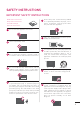
SAFETY INSTRUCTIONS IMPORTANT SAFETY INSTRUCTIONS Read these instructions. Keep these instructions. 6 Protect the power cord from being walked on or pinched particularly at plugs, convenience receptacles, and the point where they exit from the apparatus. 7 Only use attachments/accessories specified by the manufacturer. 8 Use only with the cart, stand, tripod, bracket, or table specified by the manufacturer, or sold with the apparatus.
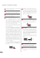
SAFETY INSTRUCTIONS 4 11 Never touch this apparatus or antenna during a thunder or lighting storm. 12 When mounting a TV on the wall, make sure not to install the TV by the hanging power and signal cables on the back of the TV. 13 Do not allow an impact shock or any objects to fall into the product, and do not drop onto the screen with something.
20 ANTENNAS Outdoor antenna grounding If an outdoor antenna is installed, follow the precautions below. An outdoor antenna system should not be located in the vicinity of overhead power lines or other electric light or power circuits, or where it can come in contact with such power lines or circuits as death or serious injury can occur. Be sure the antenna system is grounded so as to provide some protection against voltage surges and built-up static charges.
SAFETY INSTRUCTIONS 29 6 Viewing 3D Imaging ŹWhen viewing 3D imaging, watch the TV from an effective viewing angle and within the appropriate distance. If you exceed this viewing angle or distance, you may not be able to view the 3D imaging. Furthermore, the 3D imaging may not display if it is viewed while you are lying down. ŹIf you watch the 3D imaging too closely or for a long period of time, it may harm your eyesight.
CONTENTS WARNING / CAUTION ............................2 SAFETY INSTRUCTIONS ........................3 CONTENTS ......................................................6 FEATURE OF THIS TV ..............................9 PREPARATION Accessories...........................................................10 Optional Extras ..................................................... 11 Front Panel Information .................................... 12 Back Panel Information.....................................
NETCAST Netcast Menu.................................................... 123 YOUTUBE........................................................... 124 PICASA............................................................... 126 PICTURE CONTROL Picture Size (Aspect Ratio) Control............ 128 Picture Wizard................................................... 130 ᰚ Energy Saving ............................................ 132 Preset Picture Settings (Picture Mode).....
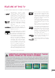
FEATURE OF THIS TV ᯫ Some of these features are not available on all models. High-definition television. Highresolution digital television broadcast and playback system composed of roughly a million or more pixels, 16:9 aspect-ratio screens, and AC3 digital audio. A subset of digital television, HDTV formats include 1080p, 1080i, and 720p resolutions. Manufactured under license from Dolby Laboratories. “Dolby “and the double-D symbol are trademarks of Dolby Laboratories.
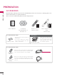
PREPARATION PREPARATION ACCESSORIES PREPARATION Ensure that the following accessories are included with your TV. If an accessory is missing, please contact the dealer where you purchased the TV. The accessories included may differ from the images below. 1.5V 1.
x4 x4 (M4 x 12) (M4 x 22) x2 Cable Holder (Refer to p.25) Screws for stand assembly (Refer to P.20) PREPARATION 47/55LX9500, 47/55LEX8, 60/72LEX9 Component gender cable, AV gender cable Stand Rear Cover Plasma TV (For 50PK950, 50PX950) x4 x4 (M4 x 14) (M4 x 28) Screws for stand assembly (Refer to P.18) x2 Cable Holder (Refer to P.24) Power Cord Protection Cover Cable (Refer to P.19) Management Clip (Refer to P.
PREPARATION FRONT PANEL INFORMATION PREPARATION ᯫ Image shown may differ from your TV. 50/60PK950, 50/60PX950 Intelligent Sensor Adjusts picture according to the surrounding conditions Remote Control Sensor SPEAKER Power/Standby Indicator Illuminates red in standby mode. The lighting is off while the TV remains on. Touch Button You can operate the button just by touching the button lightly with your finger.
PREPARATION 47/55LX9500 CH CHANNEL (ᰝ,ᰜ) Buttons VOL VOLUME (-, +) Buttons ENTER MENU SPEAKER Emitter It is the part equipped with the emitter exchanging signal with 3D glasses. Please be careful not to block the screen with objects or people while watching a 3D Video.
PREPARATION PREPARATION ᯫ Image shown may differ from your TV. 47/55LEX8, 60/72LEX9 Remote Control Sensor Intelligent Sensor Adjusts picture according to the surrounding conditions Power/Standby Indicator (Can be adjusted using the Power Indicator in the OPTION menu.Źp.142) SPEAKER Emitter Touch Button You can operate the button just by touching the button lightly with your finger.
BACK PANEL INFORMATION PREPARATION ᯫ Image shown may differ from your TV.
PREPARATION 12 USB IN 2 PREPARATION 47/55LX9500, 47/55LEX8, 60/72LEX9 3 4 RGB IN (PC) RS-232C IN (CONTROL&SERVICE) 8 /DVI IN 3 2 AUDIO IN ꔡ AUDIO OUT 1 WIRELESS CONTROL 2 Y PB PR L R 1 AUDIO VIDEO 9 8 6 H/P 5 VIDEO L(MONO) AUDIO R AV IN 1 COMPONENT IN (RGB/DVI) OPTICAL DIGITAL 11 6 IN 4 LAN AV IN2 VIDEO / AUDIO 2 COMPONENT IN3 AUDIO / Y PB PR 1 USB IN 1 10 2 ANTENNA/ CABLE IN 7 CAUTION For HDMI IN 4 and USB IN 1, 2 ŹFor an optimal connection, HDMI cables and USB devi
PREPARATION 1 2 3 4 5 LAN Network connection for Netflix, Yahoo! TV Widgets, etc (for USA). Also used for video, photo and music files on a local network. HDMI/DVI IN, HDMI IN Digital Connection. Supports HD video and Digital audio. Doesn’t support 480i. Accepts DVI video using an adapter or HDMI to DVI cable (not included). RGB IN (PC) Analog PC Connection. Uses a D-sub 15 pin cable (VGA cable). AUDIO IN (RGB/DVI) 0.32 cm (1/8 inch) headphone jack for analog PC audio input.
PREPARATION STAND INSTRUCTIONS (For 50/60PK950, 50/60PX950) PREPARATION ᯫ Image shown may differ from your TV. INSTALLATION 1 2 Carefully place the TV screen side down on a cushioned surface to protect the screen from damage. Assemble the parts of the STAND BODY with the STAND BASE of the TV. STAND BODY M4 x 14 STAND BASE 50PK950, 50PX950 (provided as parts of the product) 3 Assemble the parts of the CABLE MANAGEMENT CLIP with the STAND BODY. 4 Assemble the TV as shown.
PREPARATION DETACHMENT 1 Carefully place the TV screen side down on a cushioned surface to protect the screen from damage. 50PK950, 50PX950 2 Remove the screws that hold the stand on. M4 x 28 3 60PK950, 60PX950 M4 x 30 Detach the stand from TV. PROTECTION COVER After removing the stand, install the included PROTECTION COVER over the hole for the stand. Press the PROTECTION COVER into the TV until you hear it click. When installing the wall mounting bracket, use the PROTECTION COVER.
PREPARATION STAND INSTRUCTIONS (For 47/55LX9500, 47/55LEX8) PREPARATION ᯫ Image shown may differ from your TV. INSTALLATION 1 Carefully place the TV screen side down on a cushioned surface to protect the screen from damage. 2 Assemble the parts of the STAND BODY with the STAND BASE of the TV. At this time, tighten the screws that hold the STAND BODY on. STAND BODY M4 x 22 STAND BASE 3 Install the 4 screws into the holes shown. M4 x 12 4 Assemble the part of the STAND REAR COVER with the TV.
1 Carefully place the TV screen side down on a cushioned surface to protect the screen from damage. 2 Detach the STAND REAR COVER from TV. 3 Remove the screws that hold the stand on. 4 Detach the stand from TV.
PREPARATION VESA WALL MOUNTING PREPARATION Install your wall mount onto wooden studs perpendicular to the floor. When attaching to other building materials, please contact a professional. If installed on a ceiling or slanted wall, it may fall and result in severe personal injury. We recommend that you use an LG brand wall mount when mounting the TV to a wall. LG recommends that wall mounting be performed by a qualified professional installer.
PREPARATION ! NOTE ŹScrew length needed depends on the wall mount used. For further information, refer to the instructions included with the mount. ŹStandard dimensions for wall mount kits are shown in the table. ŹWhen purchasing our wall mount kit, a detailed installation manual and all parts necessary for assembly are provided. ŹDo not use screws longer than the standard dimension, as they may cause damage to the inside to the TV.
PREPARATION CABLE MANAGEMENT PREPARATION ᯫ Image shown may differ from your TV. Plasma TV How to use the CABLE HOLDER 1 After connecting the cables as necessary, install the CABLE HOLDER as shown and bundle the cables. In case of the LAN cable, install as shown to reduce the electromagnetic wave. CABLE HOLDER How to use the CABLE MANAGEMENT CLIP 1 2 Connect the cables as necessary. To connect additional equipment, see the EXTERNAL EQUIPMENT SETUP section.
PREPARATION ᯫ Image shown may differ from your TV. 47/55LX9500, 47/55LEX8, 60/72LEX9 1 Secure the power cord with the CABLE HOLDER on the TV back cover. It will help prevent the power cable from being removed by accident. CABLE HOLDER 2 After connecting the cables as necessary, install the CABLE HOLDER as shown and bundle the cables.
PREPARATION DESKTOP PEDESTAL INSTALLATION PREPARATION ᯫ Image shown may differ from your TV. For proper ventilation, allow a clearance of 10.1 cm (4 inch) on all four sides from the wall. 10.1 cm (4 inch) 10.1 cm (4 inch) 10.1 cm (4 inch) 10.1 cm (4 inch) CAUTION ŹEnsure adequate ventilation by following the clearance recommendations. ŹDo not mount near or above any type of heat source.
ᯫ ᯫ You should purchase necessary components to prevent the TV from tipping over (when not using a wall mount). Image shown may differ from your TV. We recommend that you set up the TV close to a wall so it cannot fall over if pushed backwards. Additionally, we recommend that the TV be attached to a wall so it cannot be pulled in a forward direction, potentially causing injury or damaging the product. Caution: Please make sure that children don’t climb on or hang from the TV.
PREPARATION ᯫ PREPARATION ᯫ To prevent damage do not connect to the power outlet until all connections are made between the devices. Image shown may differ from your TV. ANTENNA OR CABLE CONNECTION 1. Antenna (Analog or Digital) Wall Antenna Socket or Outdoor Antenna without a Cable Box Connections. For optimum picture quality, adjust antenna direction if needed.
EXTERNAL EQUIPMENT SETUP ᯫ To prevent the equipment damage, never plug in any power cords until you have finished connecting all equipment. ᯫ Image shown may differ from your TV. HD RECEIVER SETUP Component Connection 1. How to connect Y 1 Connect the video outputs (Y, PB, PR) of the digital set-top box to the COMPONENT IN VIDEO 1, 2, or 3* jacks on the TV. Match the jack colors (Y = green, PB = blue, and PR = red).
COMPONENT IN3 AUDIO / Y PB PR AV IN2 VIDEO / AUDIO H/P USB IN 1 USB IN 2 EXTERNAL EQUIPMENT SETUP 30 IN 4 EXTERNAL EQUIPMENT SETUP For LED LCD TV 1 2 R L PR PB Y
HDMI Connection RGB IN (PC) LAN 1 3 (RGB/DVI) OPTICAL DIGITAL Connect the digital set-top box to HDMI/DVI IN 1, 2, 3, or 4 jack on the TV. No separate audio connection is necessary. HDMI supports both audio and video. AUDIO IN ᯫ Turn on the digital set-top box. (Refer to the owner’s manual for the digital settop box.) ᯫ Select the HDMI1, HDMI2, HDMI3, or HDMI4 input source on the TV using the INPUT button on the remote control. AUDIO OUT 1 2 WIRELESS CONTROL Y PB PR L 1 VIDEO 1 2.
EXTERNAL EQUIPMENT SETUP DVI to HDMI Connection 3 (RGB/DVI) OPTICAL DIGITAL VIDEO L(MONO) AUDIO R 2 AUDIO IN ꔡ AUDIO OUT 1 2 WIRELESS CONTROL Y PB PR L R 1 2 Connect the digital set-top box audio output to the AUDIO IN (RGB/DVI) jack on the TV. VIDEO 1 2. How to use ᯫ Turn on the digital set-top box. (Refer to the owner’s manual for the digital settop box.) ᯫ Select the HDMI1, HDMI2, HDMI3, or HDMI4* input source on the TV using the INPUT button on the remote control.
DVD SETUP Component Connection 1 Connect the video outputs (Y, PB, PR) of the DVD to the COMPONENT IN VIDEO 1, 2, or 3* jacks on the TV. Match the jack colors (Y = green, PB = blue, and PR = red). 2 Connect the audio outputs of the DVD to the COMPONENT IN AUDIO 1, 2, or 3* jacks on the TV. Y PB PR L 1 EXTERNAL EQUIPMENT SETUP 1.
EXTERNAL EQUIPMENT SETUP Composite (RCA) Connection RGB IN (PC) RS-232C IN (CONTROL&SERVICE) /DVI IN 1 3 (RGB/DVI) OPTICAL DIGITAL AUDIO IN ᯫ ᯫ AUDIO OUT 1 S L 2. How to use ᯫ VIDEO L(MONO) AUDIO R 2 2 Y PB PR L R 1 AUDIO VIDEO Turn on the DVD player, insert a DVD. Select the AV1 or AV2 input source on the TV using the INPUT button on the remote control. Refer to the DVD player's manual for operating instructions. COMPONENT IN Connect the AUDIO/VIDEO jacks between TV and DVD.
HDMI Connection RGB IN (PC) 1 Connect the HDMI output of the DVD to the HDMI/DVI IN 1, 2, 3 or 4 jack on the TV. RS-232C IN (CONTROL&SERVICE) /DVI IN LAN 3 VIDEO L(MONO) AUDIO R AUDIO IN 2 No separate audio connection is necessary. HDMI supports both audio and video. ꔡ AUDIO OUT 1 2 WIRELESS CONTROL Y PB PR L R 1 VIDEO 2. How to use 1 ᯫ ᯫ Select the HDMI1, HDMI2, HDMI3, or HDMI4 input source on the TV using the INPUT button on the remote control.
EXTERNAL EQUIPMENT SETUP VCR SETUP Antenna Connection EXTERNAL EQUIPMENT SETUP 1. How to connect 1 2 Connect the antenna cable to the RF antenna in socket of the VCR. ANTENNA/ CABLE IN 1 ANT OUT S-VIDEO ANT IN OUTPUT SWITCH 2 VIDEO L ᯫ Set VCR output switch to 3 or 4 and then tune TV to the same channel number. Insert a video tape into the VCR and press PLAY on the VCR (Refer to the VCR owner’s manual). R AUDIO Wall Jack 2.
Composite (RCA) Connection EXTERNAL EQUIPMENT SETUP 1. How to connect 1 Connect the AUDIO/VIDEO jacks between TV and VCR. Match the jack colors (Video = yellow, Audio Left = white, and Audio Right = red) RGB IN (PC) RS-232C IN (CONTROL&SERVICE) /DVI IN 3 AUDIO OUT 1 Insert a video tape into the VCR and press PLAY on the VCR. (Refer to the VCR owner’s manual.) Select the AV1 or AV2 input source on the TV using the INPUT button on the remote control.
EXTERNAL EQUIPMENT SETUP OTHER A/V SOURCE SETUP Camcorder 1. How to connect ᯫ ᯫ Select the AV1 or AV2 input source on the TV using the INPUT button on the remote control. Operate the corresponding external equipment. USB IN 2 L R USB IN 1 2. How to use VIDEO IN 4 1 1 VIDEO L(MONO) AUDIO R H/P EXTERNAL EQUIPMENT SETUP Video Game Set Connect the AUDIO/VIDEO jacks between TV and external equipment. Match the jack colors.
HEADPHONE SETUP (FOR LED LCD TV) You can listen to the sound through headphones. Plug headphones into the headphone socket. 2 To adjust the headphone volume, press the VOL +/- button. If you press the MUTE button, the sound from the headphone is switched off. ! NOTE H/P 1 EXTERNAL EQUIPMENT SETUP 1. How to connect ŹAUDIO menu options are disabled when connecting headphones. ŹWhen changing AV MODE with headphones connected, the change is applied to video but not to audio.
EXTERNAL EQUIPMENT SETUP AUDIO OUT CONNECTION 1. How to connect N 1 Connect one end of the optical cable to the TV port of OPTICAL DIGITAL AUDIO OUT. (CONTROL&SERVICE) 3 (RGB/DVI) OPTICAL DIGITAL 2 3 Connect the other end of the optical cable to the digital audio input on the audio equipment. Set the “TV Speaker option - Off” in the AUDIO menu. (Źp.150). See the external audio equipment instruction manual for operation.
EXTERNAL EQUIPMENT WIRELESS CONNECTION (OPTIONAL EXTRAS) WIRELESS CONTROL OUT RGB IN (PC) EXTERNAL EQUIPMENT SETUP LG TVs with a Wireless Control port support the LG Wireless Media Box, which is sold separately. When you connect the wireless ready dongle (included with the media box) to the TV, external devices can be connected to the LG Wireless Media Box and video and audio will be sent to the TV wirelessly.
EXTERNAL EQUIPMENT SETUP PC SETUP This TV provides Plug and Play capability, meaning that a PC adjusts automatically to the TV's settings. RS-232C IN RGB IN (PC) (CONTROL&SERVICE) /DVI IN 1. How to connect LAN 3 (RGB/DVI) OPTICAL DIGITAL ꔡ 1 Connect the VGA output of the PC to the RGB IN (PC) jack on the TV. VIDEO L(MONO) AUDIO R 2 AUDIO IN AUDIO OUT 1 2 WIRELESS ONTROL Y PB PR L R 1 AUDIO VIDEO 2 Connect PC audio output to the AUDIO IN (RGB/DVI) jack on the TV. 2.
! NOTE ŹDepending on the graphics card, DOS mode may not work if a HDMI to DVI Cable is in use. ŹIn PC mode, there may be noise associated with the resolution, vertical pattern, contrast or brightness. If noise is present, change the PC output to another resolution, change the refresh rate to another rate or adjust the brightness and contrast on the PICTURE menu until the picture is clear. ŹAvoid keeping a fixed image on the screen for a long period of time.
EXTERNAL EQUIPMENT SETUP Screen Setup for PC mode EXTERNAL EQUIPMENT SETUP Selecting Resolution You can choose the resolution in RGB-PC mode. The Position, Phase, and Size can also be adjusted. You can choose this option only when the PC resolution is set to 1024X768, 1280X768 or 1360X768.
Auto Configure Screen Reset (Reset to original initial values) Returns Position, Size, and Phase to the default initial settings. This feature operates only in RGB-PC mode. 3,&785( ᯒ 0RYH ᯙ (QWHU ؒ &RORU ؒ 7LQW R * ؒ &RORU 7HPS W & ؒ $GYDQFHG &RQWURO ؒ 3LFWXUH 5HVHW ᯙ ᯐ ؒ /(' /RFDO 'LPPLQJ 2Q 1 ᯒ 0RYH ᰙ 3UHY 5HVROXWLRQ $XWR &RQILJ $XWR &RQILJ 6L]H $XWR &RQILJ Yes Reset Reset ᯫ 2 ENTER Select Screen (RGB-PC).
EXTERNAL EQUIPMENT SETUP Adjustment for screen Position, Size, and Phase EXTERNAL EQUIPMENT SETUP If the picture is not clear after auto adjustment or if text is shaking, adjust the picture phase manually. This feature operates only in RGB-PC mode.
NETWORK SETUP Wired Network Connection RGB IN (PC) RS-232C IN (CONTROL&SERVICE) /DVI IN LAN 1 3 VIDEO L(MONO) AUDIO R ꔡ AUDIO IN AUDIO OUT 1 WIRELESS CONTROL 2 Y PB PR L R 1 VIDEO Broadband modem Broadband Service AUDIO AV IN 1 COMPONENT IN (RGB/DVI) OPTICAL DIGITAL 2 EXTERNAL EQUIPMENT SETUP This TV can be connected to a local area network (LAN) via the LAN port. After making the physical connection, the TV needs to be set up for network communication.
EXTERNAL EQUIPMENT SETUP Wired Network Setup If wired and wireless networks are both available, wired is the preferred method. After making a physical connection, a small number of home networks may require the TV network settings to be adjusted. For detail information, contact your internet provider or router manual. EXTERNAL EQUIPMENT SETUP If you already set the Network Setting 1(7:25.
! NOTE ŹThe use of a “Router” may not be allowed or its usage may be limited depending on the policies and restrictions of your ISP. For details, contact your ISP directly. ŹThe wireless network operates at 2.4 GHz radio frequencies that are also used by other household devices such as cordless telephone, Bluetooth® devices, microwave oven, and can be affected by interference from them. It can be interrupted by the device using 5Ghz radio frequencies.
EXTERNAL EQUIPMENT SETUP Wireless Network Connection USB IN 2 USB IN 1 IN 4 VIDEO L(MONO) AUDIO R H/P EXTERNAL EQUIPMENT SETUP The LG Wireless LAN for Broadband/DLNA Adaptor, which is sold separately, allows the TV to connect to a wireless lan network. The network configuration and connection method may vary depending on the equipment in use and the network environment. Refer to the setup instructions supplied with your access point or wireless router for detailed connection steps and network settings.
Wireless Network Setup Setting up the AP (Access Point) or the wireless router is required before connecting the TV to the network. ᯒ 0RYH ᯙ (QWHU ؒ 1HWZRUN 6HWWLQJ :LUHG ؒ 1HWZRUN 6WDWXV ,QWHUQHW LV FRQQHFWHG 1HWZRUN 7\SH :LUHG QHWZRUN LV UHFRPPHQGHG ؒ /HJDO 1RWLFH ؒ (61 6HOHFWLQJ WKH ZLUHOHVV QHWZRUN VHWWLQJ W\SH 3UHYLRXV VHWWLQJ YDOXH H[LVWV 'R \RX ZDQW WR FRQQHFW ZLWK WKH SUHYLRXV VHWWLQJ" :LUHG (QWHU :LUHOHVV 5HVHWWLQJ 6HOHFW WKH ZLUHOHVV QHWZRUN VHWWLQJ W\SH 6HWWLQJ IURP W
EXTERNAL EQUIPMENT SETUP When a security code is already set PIN (Personal Identification Number) EXTERNAL EQUIPMENT SETUP If you want to connect the AP (Access Point) or router with PIN, use this feature. 6HOHFWLQJ $3 &RQQHFWLQJ ZLWK 3,1 PRGH 6HOHFW $3 \RX ZDQW WR FRQQHFW PDJH 1/1 ,QVHUW 3,1 QXPEHU DW WKH $3 ZHESDJH DQG SUHVV ؋&RQQHFW، EXWWRQ ,QSXW WKH QHZ 66,' 3,1 18%0(5 LSWLPH &RQQHFW ASW $FFHVV 3RLQW 6HDUFK 1HWZRUN )RU PRUH LQIRUPDWLRQ FKHFN WKH $3 PDQXDO ᯙ 1H[W ᯕ &RQQHFWL
AD-hoc Mode The below settings are only for connecting directly to a PC. This is the same as connecting two PCs with a cross-over cable. 6HWWLQJ $G KRF QHWZRUN 6HWWLQJ $G KRF QHWZRUN 6HOHFW WKH ZLUHOHVV QHWZRUN VHWWLQJ W\SH ,QVHUW WKH VHWWLQJ LQIRUPDWLRQ LQWR WKH GHYLFH )HDWXUHV XVLQJ H[LWLQJ QHWZRUN FDQ EH XQDYDLODEOH 'R \RX 6HWWLQJ IURP WKH $3 OLVW 1HWZRUN ,' 66,' /*79 ZDQW WR FKDQJH QHWZRUN FRQQHFWLRQ" 6HFXULW\ .H\ 6LPSOH VHWWLQJ :36 EXWWRQ PRGH (QWHU 6HWWLQJ $G KRF QHWZRUN
EXTERNAL EQUIPMENT SETUP Network Status EXTERNAL EQUIPMENT SETUP 1HWZRUN 6WDWXV 1(7:25. ᯒ 0RYH ᯙ (QWHU 79 ؒ 1HWZRUN 6HWWLQJ :LUHG ؒ 1HWZRUN 6WDWXV ,QWHUQHW LV FRQQHFWHG 1HWZRUN FRQQHFWLQJ ؒ /HJDO 1RWLFH ؒ (61 6HWWLQJ 7HVW &ORVH 6HOHFW WKH ZLUHOHVV QHWZRUN VHWWLQJ W\SH 1HWZRUN 6HWWLQJ 6HOHFW WKH ZLUHOHVV QHWZRUN VHWWLQJ W\SH 6HOHFW WKH ,3 VHWWLQJ PRGH ,3 0RGH ܁,3 $XWR 6HWWLQJ ۽ ᯘ,3 $GGUHVV ᯘ6XEQHW 0DVN ᯘ*DWHZD\
WATCHING TV / CHANNEL CONTROL REMOTE CONTROL FUNCTIONS When using the remote control, aim it at the remote control sensor on the TV. The remote control may differ from the images below. Turns the TV on from standby or off to standby. LIGHT Illuminates the remote control buttons. ENERGY SAVING Adjusts the Energy Saving setting. Źp.132 AV MODE LIGHT ENERGY AV MODE INPUT INPUT TV SAVING 1 2 ABC 3 DEF TV Toggles through preset Video and Audio modes. Źp.85 Rotates through inputs.
WATCHING TV / CHANNEL CONTROL MENU MUTE WATCHING TV / CHANNEL CONTROL MENU Q.MENU ENTER NETCAST Select the desired NETCAST menu source. Źp.123 Q.MENU Opens the list of Quick Menu options. DELETE MUTE MENU Q.MENU ENTER Źp.66 BACK WIDGETS EXIT THUMBSTICK (Up/Down/Left Right/ENTER) Navigates the on-screen menus and adjusts the system settings to your preference. BACK Allows the user to move return one step in an interactive application or other user interaction function.
ţ Controls MY MEDIA menu (Movie List, Photo List, Music List) ţ Controls the SIMPLINK compatible devices. FREEZE Pause the present picture at the screen. (It doesn’t work at USB Mode and Simplink.) The TV returns to normal viewing automatically if no signal is received or no operation is performed for 5 minutes. If you keep the screen in Freeze condition, the residual image can exist. FREEZE (For Plasma TV) INFO FREEZE SIMPLINK See a list of AV devices connected to TV.
WATCHING TV / CHANNEL CONTROL MAGIC MOTION REMOTE CONTROL FUNCTIONS Pointer Receiver WATCHING TV / CHANNEL CONTROL POWER ENTER VOL CH Blinks the light when operating. Turns the TV on from standby or off to standby. ENTER/HOME Menu Button Activates the pointer. VOLUME UP/ DOWN Adjusts the volume. CHANNEL UP/DOWN MUTE Changes the channel. Switches the sound on or off. MUTE Installing Batteries ᯫ ᯫ ᯫ ᯫ When the message "Magic motion remote control battery is low. Change the battery.
Magic Motion Remote Control Registration The Magic Motion Remote Control operates by pairing with your TV. Register the Magic Motion Remote Control after purchasing the TV. ENTER How to Re-register the Magic Motion Remote Control after Registration Failure Reset the remote control by pressing and holding both the ENTER and MUTE buttons for 5 seconds. (Once the reset is complete, the light on the Pointer RF Receiver blinks.) Then repeat the above procedure to register the remote control.
WATCHING TV / CHANNEL CONTROL Pointer Menu Options 6LPSOH 0DQXDO ([LW WATCHING TV / CHANNEL CONTROL Today 4XLFN 0HQX 30 &KDQQHO /LVW 6,03/,1. 1(7&$67 ,1387 0< 0(',$ *$0( 6&+('8/( 48,&. 0(18 1HWFDVW 6FUHHQ 5HPRWH ؒ 6SHHG ܁ 1RUPDO ۽ ؒ 6KDSH ܁ 7\SH $ ۽ ؒ 6L]H ܁ 0HGLXP ۽ ؒ $OLJQPHQW ܁ 2Q ۽ ᰙ ([LW ᯫ 1 ENTER ENTER Select Home Menu. ᯫ ᯫ 2 ᯫ ENTER Select Pointer. ENTER Make appropriate adjustments. ENTER Select Exit.