ENGLISH OWNER’S MANUAL LED LCD MONITOR Please read this manual carefully before operating your set and retain it for future reference. LED LCD MONITOR MODEL 22EA53T 23EA53T 24EA53T www.lg.
TABLE OF CONTENTS ENGLISH ENG CONTENTS 3 ASSEMBLING AND PREPARING 3 Unpacking 4 Parts and buttons 5 Setting up the Monitor set 5 - Attaching the Stand Base 6 - Detaching the Stand Base 6 - Mounting on a table 6 - Using the cable holder 8 - Mounting on a wall 9 Connecting to a PC 9 - D-SUB connection 9 - DVI-D connection 11 CUSTOMIZING SETTINGS 12 Customizing Settings 12 - Menu Settings 13 - PICTURE 14 - COLOR 15 16 - DISPLAY - OTHERS 17 MY KEY Setting 18 FUNC.
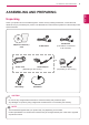
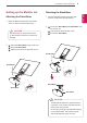
ASSEMBLING AND PREPARING 3 ASSEMBLING AND PREPARING ENG ENGLISH Unpacking Check your product box for the following items. If there are any missing accessories, contact the local dealer where you purchased your product. The illustrations in this manual may differ from the actual product and accessories. CD(Owner's Manual) / Card DVI-D Cable (This cable is not included in all countries.
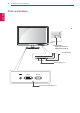
ASSEMBLING AND PREPARING Parts and buttons ENGLISH ENG Power Indicator Lighting On: Turned on Lighting Off: Turned off (Power Button) Button (See p.11) DC-IN DVI-D D-SUB Connection panel (See p.
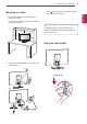
ASSEMBLING AND PREPARING Detaching the Stand Base Attaching the Stand Base 1 Place the Monitor set with the screen side down on a flat and cushioned surface. 1 Place the Monitor set with the screen side down on a flat and cushioned surface. 2 CAUTION Lay a foam mat or soft protective cloth on the surface to protect the screen from damage. 2 1 Pull out the Stand Body and Stand Base from the monitor set. 2 Turn the screw to the left with a coin. 3 Pull out the Stand Base.
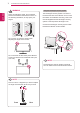
ASSEMBLING AND PREPARING Mounting on a table 3 Press (Power) button on the bottom switch position on a table. Leave a 10 cm (minimum) space from the wall for proper ventilation. CAUTION Unplug the power cord before moving the Monitor to another location. Otherwise electric shock may occur. 10 cm 10 cm 10 cm Using the cable holder 2 Connect the AC-DC Adapter and Power Cord to a wall outlet. Cable holder or ENG ENGLISH panel to turn the power on.
ASSEMBLING AND PREPARING WARNING Using the Kensington security system ENGLISH ENG When you adjust the angle, do not hold the bottom of the Monitor set frame as shown on the following illustration, as may injure your fingers. The Kensington security system connector is located at the back of the Monitor set. For more information of installation and using, refer to the manual supplied with the Kensington security system or visit http://www.kensington.com .
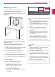
ASSEMBLING AND PREPARING Model For proper ventilation, allow a clearance of 10 cm on each side and from the wall. Detailed instructions are available from your dealer, see the optional Tilt Wall Mounting Bracket Installation and Setup Guide. VESA (A x B) Standard screw Number of screws 22EA53T 23EA53T 75 x 75 M4 4 24EA53T 100 x 100 CAUTION 10 cm 10 cm 10 cm 10 cm If you intend to mount the Monitor set to a wall, attach Wall mounting interface (optional parts) to the back of the set.
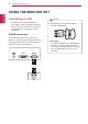
USING THE MONITOR SET USING THE MONITOR SET Your Monitor set supports Plug & Play*. *Plug & Play: A PC recognizes a connected device that users connect to a PC and turn on, without device configuration or user intervention. NOTE When using a D-Sub signal input cable connector for Macintosh D-SUB connection Transmits analog video from your PC to the Monitor set. Connect the PC and the Monitor set with the supplied D-sub 15 pin signal cable as shown in the following illustrations.
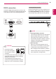
USING THE MONITOR SET Self Image Setting Function DVI-D connection Press the power button on the front panel to turn the power on. When monitor power is turned on, the "Self Image Setting" Function is executed automatically. (Only supported in Analog Mode) D-SUB NOTE "Self Image Setting" Function. DVI OUT CAUTION Connect the signal input cable and tighten it by turning the screws clockwise.
CUSTOMIZING SETTINGS 11 CUSTOMIZING SETTINGS 2 Change the value of the menu item by pressing the buttons on the bottom of the Monitor set. To return to the upper menu or set other menu items, use the up arrow ( ) button. 3 Select EXIT to leave the OSD menu. Monitor set Buttons Button Description Accesses the main menus.(See p.12) OSD LOCKED/ UNLOCKED This function allows you to lock the current control settings, so that they cannot be inadvertently changed.
CUSTOMIZING SETTINGS Customizing Settings Menu ENGLISH ENG Brightness Menu Settings 100 Contrast 1 Press MENU button on the bottom of the Monitor set to display the Menu OSD. 70 Wide/Original R Reset 2 Set the options by pressing the ◄ or ► or ▼ Wide 1/2 No 1/2 Next Menu buttons. 3 Select the "Next Menu" button to enter the more Menu > Next Menu > Picture option settings. EXIT Sharpness 5 4 Select EXIT to leave the OSD menu.
CUSTOMIZING SETTINGS 13 Picture ENG ENGLISH 1 Press MENU button on the bottom of the Monitor set to display the Menu OSD. 2 Select the "Next Menu" button to enter the more Menu > Next Menu > Picture option settings. Sharpness 5 3 Enter to Picture by pressing the ▼ button. 4 Set the options by pressing the ◄ or ► or ▼ buttons. 5 Select EXIT to leave the OSD menu. EXIT To return to the upper menu or set other menu items, use the up arrow ( ) button. Each option is explained below.
CUSTOMIZING SETTINGS Color ENGLISH ENG 1 Press MENU button on the bottom of the Monitor set to display the Menu OSD. Menu > Next Menu > Color Gamma 2 Select the "Next Menu" button to enter the more option settings. 3 Select Color by pressing the ► button. Color Temp Gamma 1 2/3 Custom 4/4 Red 50 Green 50 Blue 50 4 Enter to Color by pressing the ▼ button. EXIT 5 Set the options by pressing the ◄ or ► or ▼ buttons. 6 Select EXIT to leave the OSD menu.
CUSTOMIZING SETTINGS 15 Display ENG ENGLISH 1 Press MENU button on the bottom of the Monitor set to display the Menu OSD. 2 Select the "Next Menu" button to enter the more option settings. 3 Select Display by pressing the ► button. 4 Enter to Display by pressing the ▼ button. 5 Set the options by pressing the ◄ or ► or ▼ buttons. 6 Select EXIT to leave the OSD menu. To return to the upper menu or set other menu items, use the up arrow ( ) button. Each option is explained below.
CUSTOMIZING SETTINGS Others ENGLISH ENG 1 Press MENU button on the bottom of the Monitor set to display the Menu OSD. 2 Select the "Next Menu" button to enter the more option settings. Menu > Next Menu > Others Language 3 Select Others by pressing the ► button. Power Indicator English On 1/17 1/2 4 Enter to Others by pressing the ▼ button. 5 Set the options by pressing the ◄ or ► or ▼ DVI-D 1920 X 1080 60HZ buttons. EXIT 6 Select EXIT to leave the OSD menu.
CUSTOMIZING SETTINGS MY KEY Setting MY KEY > Picture Mode set to display the MY KEY OSD. Custom 2 Set the options by pressing the ◄or►or▼buttons. Text Photo Cinema Game MY KEY Setting 3 Select EXIT to leave the OSD menu. You can designate a feature in FUNC. as MY KEY. EXIT MY KEY > What is MY KEY? MY KEY is a short key for quick access. You can save one of FUNC. features as favorite. Go to MY KEY Setting in FUNC. menu to change favorite setting.
CUSTOMIZING SETTINGS FUNC. Setting ENGLISH ENG Picture Mode FUNC. > Picture Mode 1 Press FUNC. button on the bottom of the Monitor set to display the FUNC. OSD. Custom 2 Enter to Picture Mode by pressing the ▼ button. Text Photo Cinema Game 3 Set the options by pressing the ◄ or ► buttons. 4 Select EXIT to leave the OSD menu.To return to the EXIT upper menu or set other menu items, use the up arrow( )button. Each option is explained below.
CUSTOMIZING SETTINGS 19 SUPER ENERGY SAVING ENG ENGLISH 1 Press FUNC. button on the bottom of the Monitor set to display the FUNC. OSD. FUNC. > SUPER ENERGY SAVING 2 Select SUPER ENERGY SAVING by pressing the ► button. SUPER ENERGY SAVING is active You saved 0.00 trees 3 Enter to SUPER ENERGY SAVING by pressing the ▼ Power Reduction: CO2 Redution: button. 4 Set the options by pressing the ◄ or ► or ▼buttons. 0W 0g Off On Reset 5 Select EXIT to leave the OSD menu.
CUSTOMIZING SETTINGS * Before using below functions, please install DUAL SMART SOLUTION programme. ENGLISH ENG DUAL DISPLAY 1 Press FUNC. button on the bottom of the Monitor set to display the FUNC. OSD. FUNC. > DUAL DISPLAY 2 Select DUAL DISPLAY by pressing the ► button. 3 Enter to DUAL DISPLAY by pressing the ▼ button. Clone Off Extended 4 Set the options by pressing the ◄ or ► buttons. 5 Select EXIT to leave the OSD menu.
CUSTOMIZING SETTINGS 21 MY KEY Setting ENG ENGLISH 1 Press FUNC. button on the bottom of the Monitor set to display the FUNC. OSD. FUNC. > MY KEY Setting 2 Select MY KEY Setting by pressing the ► button. 3 Enter to MY KEY Setting by pressing the ▼ button. Picture Mode 4 Set the options by pressing the ◄ or ► buttons. 5 Select EXIT to leave the OSD menu.To return to SUPER ENERGY SAVING DUAL DISPLAY DUAL WEB Picture Mode is saved as MY KEY.
SPECIFICATIONS TROUBLESHOOTING ENGLISH ENG Check the following before calling for service. No image appears Is the power cord of the display connected? Check and see if the power cord is connected properly to the power outlet. Is the power indicator light on? Press the Power button. Adjust the brightness and the contrast.
SPECIFICATIONS 23 CAUTION Display image is incorrect The screen color is mono or abnormal. Check if the signal cable is properly connected and use a screwdriver to fasten if necessary. Make sure the video card is properly inserted in the slot. Set the color setting higher than 24 bits (true color) at Control Panel ► Settings. The screen blinks. Check if the screen is set to interlace mode and if yes, change it to the recommend resolution.
SPECIFICATIONS SPECIFICATIONS ENGLISH ENG 22EA53T Display Screen Type Sync Input Pixel Pitch Horizontal Frequency Vertical Frequency 54.6 cm (21.5 inch) Flat Panel Active matrix-TFT LCDAntiGlare coating Visible diagonal size: 54.6 cm 0.08265*RGB(H) mm x 0.24795(V) mm 30 kHz to 83 kHz (Automatic) 56Hz to 75Hz (D-SUB, DVI-D) Video Input Input Form Signal Input Separate Sync. Digital 15 pin D-SUB Connector /DVI-D Connector (Digital) Resolution Input Form Max RGB Analog (0.
SPECIFICATIONS 25 SPECIFICATIONS Display Screen Type 58.4 cm (23 inch) Flat Panel Active matrix-TFT LCDAntiGlare coating Visible diagonal size: 58.4 cm Sync Input Pixel Pitch Horizontal Frequency Vertical Frequency 0.265 mm x 0.265 mm (Pixel Pitch) 30 kHz to 83 kHz (Automatic) 56Hz to 75Hz (D-SUB, DVI-D) Video Input Input Form Signal Input Separate Sync. Digital 15 pin D-SUB Connector /DVI-D Connector (Digital) Resolution Input Form Max RGB Analog (0.
SPECIFICATIONS ENGLISH ENG SPECIFICATIONS 24EA53T Display Screen Type Sync Input Pixel Pitch Horizontal Frequency Vertical Frequency 60.4 cm (2 3.8 inch) Flat Panel Active matrix-TFT LCDAntiGlare coating Visible diagonal size: 60. 4 cm 0.2745 mm x 0.27 45 mm (Pixel Pitch) 30 kHz to 83 kHz (Automatic) 56Hz to 75Hz (D-SUB, DVI-D) Video Input Input Form Signal Input Separate Sync. Digital 15 pin D-SUB Connector /DVI-D Connector (Digital) Resolution Input Form Max RGB Analog (0.
SPECIFICATIONS Preset Modes (Resolution) ENGLISH ENG 22EA53T 23EA53T, 24EA53T Display Modes (Resolution) Horizontal Frequency(kHz) Vertical Frequency(Hz) Polarity(H/V) 720 x 400 31.468 70 -/+ 640 x 480 31.469 60 -/- 640 x 480 37.500 75 -/- 800 x 600 37.879 60 +/+ 800 x 600 46.875 75 +/+ 1024 x 768 48.363 60 -/- 1024 x 768 60.023 75 +/+ 1152 x 864 67.500 75 +/+ 1280 x 1024 63.981 60 +/+ 1280 x 1024 79.976 75 +/+ 1680 x 1050 65.290 60 -/+ 1920 x 1080 67.
PROPER POSTURE 28 PROPER POSTURE ENG ENGLISH Proper posture for using the Monitor set. Adjust the Monitor set and your posture to allow you to view images at the optimal viewing angle. Place your hands gently on the keyboard, keeping your arms bent at the elbows and horizontally outright. Adjust the location of the Monitor set to avoid it reflecting light.
Declaration of Conformity Trade Name: LG Model : 22EA53TA 23EA53TA 24EA53TA Responsible Party: LG Electronics Inc. Address : 1000 Sylvan Ave. Englewood Cliffs NJ 07632 U.S.A TEL: 201-266-2534 *above information is only for USA FCC Regulatory Make sure to read the Safety Precautions before using the product. Keep the Owner’s Manual (CD) in an accessible place for future reference. The model and serial number of the SET is located on the back and one side of the SET.