ENG ENGLISH OWNER’S MANUAL MONITOR SIGNAGE Please read this manual carefully before operating the your set and retain it for future reference. MONITOR SIGNAGE MODELS 26TS30MF 47TS30MF www.lg.
CONTENTS ENGLISH ENG CONTENTS 3 INSTALLATION PREPARATION 3 Accessories 4 Mounting Holes 6 Unpacking and Cabling 8 Portrait Layout (Only supported for 47TS30MF) 9 Storage Method for Panel Protection 9 - Correct Method 9 - Incorrect Method 10 PRODUCT INSTALLATION 10 Lighting installation 11 Installation in Enclosure 12 Precaution 12 - Correct Method 12 - Incorrect Method 13 TROUBLESHOOTING 14 SPECIFICATIONS 14 26TS30MF 15 47TS30MF 16 LVDS PIN MAP GUIDE 16 26TS30MF
INSTALLATION PREPARATION 3 Accessories Check your product box for the following items. If there are any missing accessories, contact the local dealer where you purchased your product. The illustrations in this manual may differ from the actual product and accessories. CD (Owner's Manual)/ Card/ Easy Setup Guide CAUTION Do not use any unapproved or counterfeit parts or accessories to ensure the safety and product life yy span.
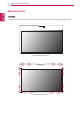
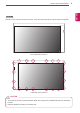
INSTALLATION PREPARATION Mounting Holes ENGLISH ENG 26TS30MF Use M3 x 4 mm screws to mount the monitor. There are 16 screw holes on the rear side of the product.
INSTALLATION PREPARATION Use M3 x 4 mm screws to mount the monitor. There are 20 screw holes on the rear side of the product. < Front side of the product > < Rear side of the product > CAUTION This product has the front and back sides. Make sure the product is installed with the front side facing yy forward. Image is displayed reversely on the back side.
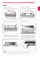
INSTALLATION PREPARATION Unpacking and Cabling ENGLISH ENG 26TS30MF 1 Lift up the cover of the box. 2 Remove the top packaging. 3 Hold both sides of the product and lift it up. 4 Remove the poly bag. 5 Place a soft cloth on the table and put the 6 Connect the LVDS cable(Additional assembly product down with the screen facing downward. is required). A scaler board or LVDS cable is optional and not provided with the product.
INSTALLATION PREPARATION 7 47TS30MF 2 Remove the top packaging. 3 Hold both sides of the product and lift it up. 4 Remove the poly bag. 5 Place a soft cloth on the table and put the 6 Connect the LVDS cable(Additional assembly product down with the screen facing downward. is required). A scaler board or LVDS cable is optional and not provided with the product. NOTE Please refer to "LVDS Pin Map Guide" on pages 16 to 18 for the LVDS cable assembly. yy ENG ENGLISH 1 Lift up the cover of the box.
INSTALLATION PREPARATION Portrait Layout (Only supported for 47TS30MF) ENGLISH ENG To install in portrait mode, rotate the set clockwise 90 degrees when looking at from the front. The portrait mode is only available on the scaler board.(The scaler board should support portrait mode.) CAUTION The 26TS30MF model cannot be rotated. yy The scaler board is optional and it is not part of the product.
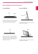
INSTALLATION PREPARATION 9 Storage Method for Panel Protection Panel ENG ENGLISH Correct Method Incorrect Method Cushion Panel When laying down the product, place a cushion or a soft cloth on a flat floor. Put the product down with the panel of the product facing down. Panel If there is no a cushion or a soft cloth available, ensure the floor is clean. Then lay the product down carefully with the panel facing either upward or downward. At this time, make sure that no object falls on the panel.
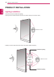
PRODUCT INSTALLATION ENGLISH ENG PRODUCT INSTALLATION Lighting installation This product must be installed with lighting. Lighting must be installed behind the product so that the display can be seen clearly. Lighting 600 lux or more Installing a certain object behind the screen may require additional lighting.
PRODUCT INSTALLATION 11 Installation in Enclosure ENG ENGLISH Install the product in the enclosure. 1 Place the product in the enclosure. 2 Attach the product using the prepared screw holes and an additional enclosure guide frame. < Example of the product in the enclosure > NOTE This product can be installed in various yy locations besides the enclosure. CAUTION The panel of this product is so thin that it yy can be easily broken when it is exposed to the outside.
INSTALLATION PREPARATION Precaution ENGLISH ENG Correct Method Incorrect Method Do not hold the screen area when holding the product. Do not lift up the product by holding a corner. CAUTION Use a soft cloth moistened with n-hexane to remove dust or stains on the screen. Make sure the power is disconnected before yy moving or installing the product.Otherwise electric shock may occur. If you install the product on a ceiling or yy slanted wall, it may fall and result in severe injury.
TROUBLESHOOTING 13 After-image appears on the product. Problem After-image appears when the product is turned off. Resolution yy If you use a fixed image for a long time, the pixels may be damaged quickly. Use the screen-saver function. Screen color is abnormal. Problem creen color is unstable or S mono-colored. Do black spots appear on the screen? Resolution yy Check the connection status of the LVDS cable.
SPECIFICATIONS ENGLISH ENG SPECIFICATIONS 26TS30MF EEPROM RGB Source Driver Circuit SCL SDA S1 S1366 G1 LVDS Select #9 CN1 (30pin) LVDS 1Port Timing Controller [LVDS Rx] TFT - LCD Panel Control Signals (1366 x RGB x 768 pixels) [Gate In Panel] +12.0V Power Circuit Block G768 Power Signals Screen Size 26.01 inche (660.6 mm) diagonal Dimension(W x H x D) 609 mm x 412.8 mm x 8.8 mm Pixel Pitch 140.5 ㎛ x RGB X 421.5 ㎛ Pixel Format 1366 horiz. by 768 vert.
SPECIFICATIONS ENG ENGLISH 47TS30MF Mini-LVDS (RGB) EEPROM Source Driver Circuit SCL LVDS 2Port LVDS 1,2 LVDS Select Option signal CN1 Bit Select 15 (51pin) SDA S1 G1 Timing Controller LVDS Rx + DCA + ODC Intergrated TFT - LCD Panel (1920 x RGB x 1080 pixels) [Gate In Panel] Control Signals I2C S1920 +12.0V G1080 Power Circuit Block Power Signals Screen Size 46.96 inch (1192.87mm) diagonal Dimension(W x H x D) 1165.9 mm x 663.27 x 8.8 mm Pixel Pitch 0.5415 mm x 0.
LVDS PIN MAP GUIDE ENGLISH ENG LVDS PIN MAP GUIDE 26TS30MF LVDS Connector(CN1) : KDF71G-30S-1H(Hirose) or Compatible, Refer to below table. yy Mating Connector : FI-X30C2L(Manufactured by JAE) or Equivalent yy Cable length: 1 m of FFC cable or less yy Pin No. Symbol 1 VLCD Power Supply+12.0V Description 2 VLCD Power Supply+12.0V 3 VLCD Power Supply+12.0V 4 VLCD Power Supply+12.
LVDS PIN MAP GUIDE 17 47TS30MF ENG ENGLISH LVDS Connector(CN1) : FI-RE51S-HF or Equivalent, Refer to below table. yy Mating Connector : FI-RE51S or Equivalent yy Cable length: 1 m of coaxial cable or less yy Pin No.
LVDS PIN MAP GUIDE ENGLISH ENG Pin No. Symbol 42 NC No Connection Description 43 NC No Connection 44 NC No Connection 45 GND Ground 46 GND Ground 47 GND Ground 48 VLCD Power Supply+12.0V 2 49 VLCD Power Supply+12.0V 2 50 VLCD Power Supply+12.0V 2 51 VLCD Power Supply+12.0V 2 Note : 1. All GND (Ground) pins should be connected together to the LCD module's metal frame. 2. All VLCD (power input) pins should be connected together. 3.
Make sure to read the Safety Precautions before using the product. Keep the Owner's Manual(CD) in an accessible place for future reference. The model and serial number of the SET is located on the back and one side of the SET. Record it below should you ever need service. MODEL SERIAL Temporary noise is normal when powering ON or OFF this device.