OWNER’S MANUAL MONITOR SIGNAGE Please read this manual carefully before operating the your set and retain it for future reference. MONITOR SIGNAGE MODELS 47TS50MF www.lg.
CONTENTS ENGLISH ENG CONTENTS 3 INSTALLATION PREPARATION 3 Accessories 4 Mounting Holes 5 Portrait Layout 6 Storage Method for Panel Protection 6 - Correct Method 6 - Incorrect Method 7 PRODUCT INSTALLATION 7 Installing an LVDS Cable 8 Lighting Installation 9 Installation in Enclosure 10 Precaution 10 - Correct Method 10 - Incorrect Method 11 TROUBLESHOOTING 12 SPECIFICATIONS 14 LVDS PIN MAP GUIDE NOTE The warranty will not cover any damages caused by using the product
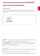
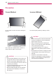
INSTALLATION PREPARATION 3 Accessories Check your product box for the following items. If there are any missing accessories, contact the local dealer where you purchased your product. The illustrations in this manual may differ from the actual product and accessories. CD (Owner's Manual)/ Easy Setup Guide NOTE The accessories supplied with your product may vary depending on the model.
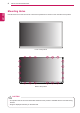
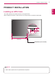
INSTALLATION PREPARATION Mounting Holes ENGLISH ENG Use M3 screws to mount the monitor. There are 20 positions for screws on the rear side of the product. Front of the product Rear of the product CAUTION This product has the front and back sides. Make sure the product is installed with the front side facing yy forward. Image is displayed reversely on the back side.
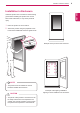
INSTALLATION PREPARATION 5 Portrait Layout CAUTION The scaler board is optional and it is not part of the product. yy ENG ENGLISH To install in portrait mode, rotate the set clockwise 90 degrees when looking at from the front. The portrait mode is only available on the scaler board. (The scaler board should support portrait mode.
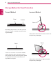
INSTALLATION PREPARATION Storage Method for Panel Protection ENGLISH ENG Correct Method Panel Incorrect Method Cushion Panel When laying the product on a flat floor, pit it face down on a cushion or blanket to prevent scratching and damage. If the product is tilted onto the bezel, the bottom of the panel may be damaged. Panel If there is no a cushion or a soft cloth available, ensure the floor is clean. Then lay the product down carefully with the panel facing either upward or downward.
PRODUCT INSTALLATION Installing an LVDS Cable The LVDS cable port is located as shown in the figure below. When installing the product, make sure there is enough space to install the LVDS cable. 30 mm 45 mm 542.25 mm LVDS Cable (not included) NOTE LVDS cable is optional and not provided with the product.
PRODUCT INSTALLATION Lighting Installation ENGLISH ENG This product must be installed with backlighting. Lighting must be installed behind the product so that the display can be seen clearly. 600 lux or more (When the Full Screen is White.) Lighting If something obstructs the backlighting, additional lighting may be required. Additional lighting 600 lux or more (When the Full Screen is White.
PRODUCT INSTALLATION 9 Installation in Enclosure ENG ENGLISH Install the product in the enclosure. Wear working gloves when installing the product. Do not use bare hands. Otherwise, it may cause personal injury. 1 Place the product in the enclosure. 2 Attach the product using the prepared screw holes and an additional enclosure guide frame. Example of the product in the enclosure NOTE This product can be installed in various yy locations besides the enclosure.
PRODUCT INSTALLATION Precaution ENGLISH ENG Correct Method Incorrect Method Do not hold the screen area when holding the product. Do not lift up the product by holding a corner. CAUTION Use a soft cloth moistened with n-hexane to remove dust or stains on the screen. CAUTION If a fixed image displays on the screen for a yy long period of time, it will be imprinted and become a permanent disfigurement on the screen. This is image burn or burn-in and not covered by the warranty.
TROUBLESHOOTING 11 After-image appears on the product. Problem After-image appears when the product is turned off. Resolution yy If you use a fixed image for a long time, the pixels may be damaged quickly. Use the screen-saver function. yy When a dark image is displayed on the screen after an image with high contrast (black and white or gray), this may cause image sticking. This is normal for LCD screen. Screen color is abnormal. Problem Resolution creen color is unstable or S mono-colored.
SPECIFICATIONS ENGLISH ENG SPECIFICATIONS Screen Size 46.96 inch (1192.87mm) diagonal Dimension (W x H x D) 1084.5 mm x 653 mm x 11.2 mm Pixel Pitch 0.5415 mm x 0.5415 mm Pixel Format 1920 horiz. by 1080 vert. Pixels, RGB stripe arrangement Color Depth 8Bit (D), 16.7 Million colors Transmittance (With POL) 6.4 % (Typ.) Viewing Angle (CR>10) Viewing angle free ( R/L 178 (Min.), U/D 178 (Min.)) Power Consumption Total 6.1 W (Typ.)(TBD) Weight (head) 2.
SPECIFICATIONS 13 3 3 1084.5 130 304.5 130 130 130 130 130 130 105.4 130 105.4 130 653 130 160 130 127.6 127.6 130 160 130 20-M3 Tap Hole 130 130 130 304.5 11.
LVDS PIN MAP GUIDE ENGLISH ENG LVDS PIN MAP GUIDE yyLCD Connector(CN1) : FI-RE51S-HF or Equivalent, Refer to below table. yyMating Connector : FI-RE51HL Cable length: 1 m of coaxial cable or less yy Pin No.
LVDS PIN MAP GUIDE Symbol 41 NC Description 42 NC or GND No Connection or Ground 43 NC or GND No Connection or Ground 44 GND Ground 45 GND Ground 46 GND Ground 47 NC 48 VLCD Power Supply+12.0V 2 49 VLCD Power Supply+12.0V 2 50 VLCD Power Supply+12.0V 2 51 VLCD Power Supply+12.0V 2 No Connection Note 4 5 No Connection Note : 1. All GND (ground) pins should be connected together to the LCD module’s metal frame. 2.
Make sure to read the Safety Precautions before using the product. Keep the Owner's Manual (CD) in an accessible place for future reference. The model and serial number of the SET is located on the back and one side of the SET. Record it below should you ever need service. MODEL SERIAL Temporary noise is normal when powering ON or OFF this device.