AR720’S_LGESA_ENG_MFL39518807 AV RECEIVER SYSTEM OWNER’S MANUAL MODEL: AR702TT Main Unit - AR702TT-AD Speakers - SR72TT-F, SR72TT-C, SR72TT-B SR72TT-A AR702TS Main Unit - AR702TS-AD Speakers - SR72TS-F, SR72TS-C, SR72TS-L SR72TS-B, SR72TS-A AR702BR Main Unit - AR702BR-AD Speakers - SR72BR-L, SR72BR-B, SR72BR-S SR72BR-A AR702NS Main Unit - AR702NS-AD Before connecting, operating or adjusting this product, please read this instruction booklet carefully and completely.
CAUTION RISK OF ELECTRIC SHOCK DO NOT OPEN CAUTION: TO REDUCE THE RISK OF ELECTRIC SHOCK DO NOT REMOVE COVER (OR BACK) NO USER-SERVICEABLE PARTS INSIDE REFER SERVICING TO QUALIFIED SERVICE PERSONNEL. This lightning flash with arrowhead symbol within an equilateral triangle is intended to alert the user to the presence of non insulated dangerous voltage within the product’s enclosure that may be of sufficient magnitude to constitute a risk of electric shock to persons.
Contents Introduction . . . . . . . . . . . . . . . . .4-11 Before use . . . . . . . . . . . . . . . . . . . . . . . . .4 Before connection . . . . . . . . . . . . . . . . . . .4 Symbol Used in this Manual . . . . . . . . . . . .4 Required cables . . . . . . . . . . . . . . . . . . . . .4 Front Panel . . . . . . . . . . . . . . . . . . . . . . . .5 Rear Panel . . . . . . . . . . . . . . . . . . . . . . . .6 Active Subwoofer . . . . . . . . . . . . . . . . . . . .7 Display window . . . . . . . . . . . . . .
Introduction Before use • To ensure proper use of this product, please read this owner’s manual carefully and keep this manual in an easily accessible place for future reference. A/V Analog audio/Composite video cable Yellow (video) White (L/audio) • This manual provides information on the operation and maintenance of your unit. Should the unit require service, contact an authorized service location.
Front Panel 2 3 4 5 6 8 7 INPUT SELECT Introduction 1 MASTER VOLUME /l 2EQ DISPLAY 10 9 12 11 14 13 16 15 M1 18 17 1. POWER ( ) Sets the unit to On and Standby. 2. INPUT SELECT Select the input source. Turn this knob until the input source you want appears in the display window. 3. AUDYSSEY (2EQ) LED indicator Lights up when Audyssey 2EQ is active. 4. DISPLAY Displays various information about the currently selected input source. 5. Display window 6.
Rear Panel 2 1 3 4 5 6 7 8 9 10 + - 11 1. HDMI IN 1/2 Connect the component with HDMI output. 2. HDMI OUT Connect a TV or component with HDMI input. 3. VCR IN/VCR REC. OUT Connect a VCR. 4. TV/STB IN Connect a TV, satellite tuner or set-top box. 5. DVD IN Connect a DVD player to DVD IN jacks. 6. CD IN Connect a CD player or Super Audio CD player to CD IN jacks. 7. MONITOR OUT Connect to a video input on your TV or projector. 8.
1 2 Introduction Active Subwoofer 3 4 5 6 1. LED indicator 3. Frequency Controller (70Hz - 180Hz) The RED lights when active subwoofer does not receive a input for about 10 minutes. (Standby mode.) Turn HIGHCUT dial clockwise/counterclockwise to adjust the frequency. 4. INPUT The BLUE lights when active subwoofer is receiving a input. Connect the unit’s SW(PRE OUT) to INPUT of active subwoofer. 2. Adjusting Volume (MIN - MAX) 5.
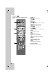
Remote Control Remote control operation range RECEIVER Mode Point the remote control at the remote sensor and press the buttons. • Distance: About 23 ft (7 m) from the front of the remote sensor To set the remote control to RECEIVER mode, press RECEIVER. • Angle: About 30° in each direction in front of the remote sensor RECEIVER 1 Remote control battery installation Remove the battery cover on the rear of the remote control, and insert two R06 (size AA) batteries with and aligned correctly.
2. DIGITAL Press this button to assign one of the digital inputs to a source. Selects HDMI 1 or HDMI 2 on the HDMI mode. DIMMER Press this button to adjust the brightness of the display window. SLEEP Press this button to set the sleep timer. AUTO CAL. Starts Audyssey 2EQ automatic speaker setup; and turns Audyssey 2EQ On and Off when setup has been performed. SPK LEVEL Adjusts the speaker level from -10dB to +10dB. TEST TONE Checks the position and sound balance of speakers in the following order.
DVD Mode DVD To set the remote control to DVD mode, press DVD. 1 2 3 4 10 1. POWER ( ) Switches the unit ON and OFF. x) 2. STOP (x Stops playback. PLAY (B) Starts playback. X)/STEP PAUSE(X Pauses playback temporarily. Press this button repeatedly to play Frame-by-Frame. REPEAT Repeats chapter, track, title or all. bb/B BB) SCAN(b Searches backward or forward. ./> >) SKIP (. Moves to the next or previous chapter or track. 3. DISPLAY Accesses On-Screen display. MENU Access the menu on a disc.
VCR To set the remote control to VCR mode, press VCR. 1 2 TV Mode TV To set the remote control to TV mode, press TV. Introduction VCR Mode 1 2 3 3 1. POWER ( ) Switches the unit ON and OFF. 4 2. CH (-/+) Selects the channel. MUTE Mutes the sound. TV INPUT Selects the TV’s source. VOLUME (-/+) Adjusts the volume. 1. POWER ( ) Switches the unit ON and OFF. x) 2. STOP (x Stops playback. PLAY (B) Starts playback. X)/STEP PAUSE(X Pauses playback temporarily.
Installation Connecting components with digital audio output jacks Connecting a DVD player (or Digital device), TV monitor or satellite tuner (or Set top box etc.) 1. Connect the audio jacks. For details of the required cables, see the page 4. DVD player (or Digital device) OPTICAL OUT COAXIAL OUT COAXIAL Optical + - OPTICAL OUT Optical Satellite tuner (or Set top box etc.
TV monitor VIDEO INPUT Installation 2. Connect the video jacks. For details of the required cables, see the page 4. The following illustration shows how to connect a TV or satellite tuner (Set top box, etc) and a DVD player with COMPONENT VIDEO (Y, CB/PB, CR/PR) output jacks. DVD player (or Digital device) COMPONENT VIDEO INPUT COMPONENT VIDEO OUT COMPONENT VIDEO COMPONENT + - VIDEO VIDEO OUT COMPONENT VIDEO OUT Satellite tuner (or Set top box, etc) COMPONENT 3.
Connecting components with analog audio jacks Connecting audio components 1. Connect the audio jacks with analog audio cable. For details of the required cables, see the page 4. Satellite tuner (or Set top box etc.) VCR AUDIO OUT AUDIO OUT DVD player AUDIO OUT CD player AUDIO OUT L L L L R R R R + - 2. Connect the video jacks with composite video cable. For details of the required cables, see the page 4. Satellite tuner (or Set top box etc.
Connecting a camcorder or game console INPUT SELECT Installation 1. Connect the audio and video jacks. For details of the required cables, see the page 4. MASTER VOLUME /l 2EQ DISPLAY M1 M2 M3 AUDIO AUDIO OUT L VIDEO OUT R VIDEO Camcorder or game console 2. Connect the unit’s MONITOR OUT jack to the TV’s VIDEO IN jack with composite video cable. For details of the required cables, see the page 4. TV monitor VIDEO INPUT VIDEO + - 3. Select the input source to play the component.
Connecting PC, Portable device, or USB device For details of the required cables, see the page 4. Select the input source to play the component after connecting. - For details, see the page 25. PC-LINK Connection (P) Connect the unit’s PC-LINK jack to the corresponding jack of PC with USB cable. Portable device Connection (L) Connect the unit’s PORTABLE-IN jack to the corresponding jack of portable device with mini stereo (3.5mm) cable.
Connecting video components for Playback Installation 1. Connect the audio jacks. For details of the required cables, see the page 4. 2. Connect the video jack and then connect your TV to the MONITOR OUT jack. You can watch the video from the selected input. + - VIDEO IN OUT VIDEO OUTOUT VIDEO IN VIDEO OUT AUDIO IN L AUDIO OUT L R R VIDEO VIDEO VIDEO INPUT AUDIO VCR TV monitor 3. Select the input source to play the component. For details, see the page 25.
Connecting video components for Recording This section explains how to connect a VCR for recording from a TV or another VCR. 1. Connect the unit’s VCR REC. OUT jack to a video input on the recording VCR. 2. Connect the unit’s VCR REC. OUT L/R jacks to an audio input L/R on the recording VCR. 3. Connect the unit’s TV/STB IN, DVD IN, CD IN, or AV IN jack to a device with video output. 4. Connect the unit’s TV/STB IN, DVD IN, CD IN, or AV IN L/R jacks to an device with audio output.
Connecting TV or components with HDMI jack Installation HDMI (High Definition Multimedia Interface) supports both video and audio on a single digital connection for an easy all- digital output to an HDMI or DVI-equipped TV. Connection to an HDMI TV requires an HDMI cable while connection a DVI-equipped TV requires a DVI adapter besides a HDMI cable.
Connecting the antennas Connect the supplied AM loop antenna and FM wire antenna. AM Loop Antenna (supplied) FM Wire Antenna (supplied) + - Notes • To prevent noise pickup, keep the AM Loop antenna away from the unit and other components. • Be sure to fully extend the FM wire antenna. • After connecting the FM wire antenna, keep it as horizontal as possible.
The unit allows you to use 6.1 channel system. The ideal surround speaker system for this unit is 6speaker systems, using front left and right speakers, a center speaker, surround left and right speakers, surround center speaker, and a subwoofer. You can enjoy high fidelity reproduction of DVD software recorded in the Surround EX format if you connect the surround center speaker (6.1 channel). For best results we recommend that all front speakers be of the same type, with identical or similar driver units.
Speaker System Connection For the best surround sound, you should connect 6 speakers and/or a powered subwoofer. Connect the your front, center, surround, surround center speakers, and subwoofer by using the speaker wires. Using a suitable cable, connect the SW (PRE OUT) to an input on optional powered subwoofer, as shown below.
Operation Audyssey 2EQ Automatic Speaker Setup Before connecting the power cord, connect all your speakers and AV components. 1. Plug the power cord into an AC wall outlet. 2. Press the POWER ( or ) button. The unit turns on, the display window lights up. /l To turn off the unit, press the POWER ( button. The unit will enter the Standby mode. /l or ) Operation Turning On the unit With the bundled speaker setup microphone ( 3.
2. Press AUTO CAL.. "Audyssey 2EQ", “AUTO CAL. : START” and “AUTO CAL. : 1ST-P” flash in the display window in turn. 3. Press ENTER. - “FL TESTING..” appears in the display window. - The speaker setup function is automatically measured in the first position from each speaker. FL TESTING..→C TESTING..→FR TESTING..→ SR TESTING..→SC TESTING..→SL TESTING.. →SW TESTING.. - After completed, the “B 2nd-POS CAL.” appears in the display window.
This section explains how to select the input source (i.e., the AV component that you want to listen to or watch). 1. Press POWER ( /l or ) to turn the unit on. 2. Select a source by rotating the INPUT SELECT on the front panel. The selected source appears in the display window. To select the Display Built-in tuner Tuner or frequency DVD player DVD Portable player Portable VCR VCR 3. Turn on the component and start playback. 4.
Switching the audio signal This section explains how to switch the audio input/output signal about each function mode. (O: Active, X: Inactive) Input/ Output Output Input • • • • OPTICAL 1 OPTICAL 2 OPTICAL 3 COAXIAL Function mode Analog RCA input (VCR, TV/STB, DVD, CD, Portable, AV) TUNER X X X O O DVD O O X O O X Portable O X X O O X • HDMI 1 • HDMI 2 Speaker terminal VCR REC.
You can enjoy the media files such as image files (JPEG), video files and Music files (MP3/WMA) saved in an MP3 player or USB memory by connecting the storage device to the USB port of this unit. Basic Operation 1. Rotate the INPUT SELECT on the front panel until the “USB” appears in the display window. Or press RECEIVER on the remote control, and then press INPUT.SEL. And then press the USB on the remote control. “NO USB” appears in the display window. 2.
Listening to FM/AM radio Presetting radio stations You can listen to FM and AM broadcasts through the built-in tuner. Before operation, make sure you have connected the FM and AM antennas to the unit. You can preset up to 50 FM or AM stations. Then you can easily tune in the stations you often listen to. Automatic tuning 1. Rotate INPUT SELECT to select tuner (FM or AM). Or select TUNER with the remote control to select tuner (FM or AM).
Displaying Source Information You can adjust the brightness of the display window. You can display various information about the current input source. Press RECEIVER, and then press DIMMER on the remote control repeatedly. The brightness of the display window is on/off. Using the Mute Function You can temporarily mute the output of the unit. Press RECEIVER, and then press MUTE. The output is muted and the “MUTE” flashes in the display window. To cancel it, press the MUTE again, or adjust the volume.
Selecting setup menu By using the Setup menu, you can make various adjustments to items such as sound. Setup configuration 1 . SURROUND A) PL2X-PANO : N/Y B) PL2X-DIM. : -7 ~ +7 C) PL2X-CWID : 0 ~ 7 D) Neo:6-CG : 0.0 ~ 1.0 2 . SPK TYPE FRONT LR : SMALL / LARGE CENTER : SMALL / LARGE / NONE SURR. LR : SMALL / LARGE / NONE SURR. C : SMALL / LARGE / NONE LFE OUT : FRONT / SUBWF / BOTH 3 . X - OVER X - OVER : 040Hz ~ 200Hz 4 . SPK DISTANCE DELAY FL : 0.0M ~ 15.0M DELAY C : 0.0M ~ 15.0M DELAY FR : 0.
You can set the size of the speakers connected to this unit. 2 . SPK TYPE FRONT LR : SMALL / LARGE CENTER : SMALL / LARGE / NONE SURR. LR : SMALL / LARGE / NONE SURR. C : SMALL / LARGE / NONE LFE OUT : FRONT / SUBWF / BOTH FRONT LR (FRONT LEFT/RIGHT) Set the FRONT L/R speaker to LARGE or SMALL. • LARGE : If you connect large speakers that will effectively reproduce bass frequencies, select “LARGE”. Normally, select “LARGE”.
4. SPK DISTANCE (Setting speaker distance) You can set the distance of the speakers connected to this unit. Initial value is 3.0 meter (10 feet). It lets you set the distance from your listening position to the front, center, surround, surround center, and subwoofer speakers. You can adjust from 0 meter to 15 meters (0 to 50 feet) in 0.3 meter (1 foot) steps. If you press DISPLAY during setting the distance, the unit of distance is changed from M (Meter) to Ft (Feet) in the display window.
8. LOAD INITIAL Enjoying the listening mode This procedure can be used to initialize settings you have made to their factory. SURROUND mode LOAD INIT : NO / YES LOAD INIT • NO : The unit does not initializes settings you have to the made to their factory default settings. • YES : The unit initializes settings you have to the made to their factory default settings. While “LOAD INIT : YES” appears in the display window, press ENTER on the remote control.
DSP (Digital Sound Processor) mode ENHANCER mode Press RECEIVER, and then press DSP repeatedly to select the DSP (Digital Sound Processor) mode you want. The selected sound appears in the display window. This mode enhances the sound quality of compressed input signal (MP3, WMA, etc) from front speakers and subwoofer. Display Description CINEMA Reproduces the powerful sound of movie theater. Press RECEIVER, and then press ENHANCER repeatedly to enhance the sound quality.
About Listening mode The following table lists all the listening modes and shows which modes can be selected for each input signal format. (O: Active, X: Inactive) Input Signal Front L Front R Channels Signal Function Buttons BYPASS SURROUND DSP ENHANCER Listening mode Front L/R Center Front L Rear L/R Front R Rear back RCA/ TUNER/ spdif/ HDMI/ HDMI USB/ PC-LINK/ Portable spdif/ HDMI DTS 3/2.
Adjusting the speaker level You can adjust the level of each speaker. 1. Press RECEIVER, and then press SPK LEVEL. b / B to adjust the level of each 2. Use v / V/b speaker. For details, see “5. SPK LEVEL (Setting speaker level)” on the page 32. To cancel it, press SPK LEVEL again. AV Sync. (Adjusting the audio delay) You may compensate for the difference through the use of delay settings in your listening position. The audio delay is adjusted from 0msec to 300msec in 10msec steps. 1.
With the NIGHT function, you can reduce the dynamic range of Dolby Digital material so that you can still hear quiet parts even when listening at low volume levels—ideal for watching movies late at night when you don’t want to disturb anyone. 1. Press RECEIVER, and then press NIGHT repeatedly to select: [NIGHT : OFF] - Late Night function off. [NIGHT : STD] - Small reduction in dynamic range. [NIGHT : MAX] - Big reduction in dynamic range.
Reference Mini Glossary for Audio Stream & Surround mode Dolby Digital EX Dolby Pro Logic IIx Dolby Digital EX creates 6 full-bandwidth output channels from 5.1-channel sources. This is done using a matrix decoder that drives three surround channels from the two in the original recording. For best results, Dolby Digital EX should be used with movies soundtracks recorded with Dolby Digital Surround EX. Dolby Pro Logic IIx is the latest extension of Dolby Pro Logic II technology that creates a discrete 6.
DTS / DTS-ES | Neo:6 DTS Neo : 6™surround “DTS” and “DTS-ES | Neo:6” are registered trademarks of DTS, Inc. “96/24” is a trademark of DTS, Inc. This mode applies conventional 2-channel signals such as digital PCM or analog stereo signals to the high precision digital matrix decoder used for DTS-ES Matrix 6.1 to achieve 6.1-channel surround playback. DTS Neo : 6 surround includes two modes for selecting the optimum decoding for the signal source.
Troubleshooting Check the following guide for the possible cause of a problem before contacting service. PROBLEM No power. No sound. No sound from the surround speakers. POSSIBLE CAUSE • Connect cord securely. • Poor connection at AC wall outlet or the outlet is dead or off. • Check the outlet using a lamp or another appliance. • The speaker wires are disconnected. • Check the speaker connections. • The MASTER VOLUME is adjusted too low. • Adjust the MASTER VOLUME.
Specifications General Refer to main label. 130 W 4.94 kg 430 x 150 x 300 mm (W x H x D) Temperature: 5°C to 35°C Reference Power supply Power consumption Net Weight External dimensions Operating conditions Amplifier Frequency response Signal-to-noise ratio 10 - 22000 Hz More than 80 dB (Analog : 1 kHz, NOP -3 dB, 20 kHz LPF/A-Filter) More than 95 dB (Digital : 1 kHz, NOP -3 dB, 20 kHz LPF/A-Filter) More than 70 dB (PC-LINK : 1 kHz, NOP -3 dB, 20 kHz LPF/A-Filter) (Y) 1.0 V, (PB)/(PR) 0.
Speaker Front Speaker (SR72TT-F) Type Bass Reflex 2 Way 2 Speaker System Impedance Surround Speaker (SR72TT-F) Sealed Type 2 Way 3 Speaker System Bass Reflex 2 Way 3 Speaker System 8Ω Frequency Response 40 - 20000 Hz Sound Pressure Level 83 dB/W (1m) 8Ω 8Ω 80 - 20000 Hz 40 - 20000 Hz 81 dB/W (1m) 83 dB/W (1m) Rated Input Power 140 W 140 W 140 W Max. Input Power 280 W 280 W 280 W Net Dimensions (W x H x D) Net Weight (1EA) Type Impedance 206 x 1003 x 270.5 mm 391 x 147.5 x 190.
Type Impedance Center speaker (SR72BR-B) Bass Reflex 2 Way 2 Speaker System 8Ω Frequency Response 80 - 20000 Hz Sound Pressure Level 81 dB/W (1m) Surround Speaker (SR72BR-S) Bass Reflex 1 Way 1 Speaker System 8Ω 8Ω 80 - 20000 Hz 100 - 20000 Hz 81 dB/W (1m) 81 dB/W (1m) Rated Input Power 70 W 70 W 70 W Max. Input Power 140 W 140 W 140 W 146 x 238 x 183.5 mm 321 x 148 x 158.5 mm 114 x 186 x 146 mm 2.2 kg 2.48 kg 1.
P/NO : MFL39518807