ROOM AIR CONDITIONER SERVICE MANUAL CAUTION - BEFORE SERVICING THE UNIT, READ THE SAFETY PRECAUTIONS IN THIS MANUAL.
CONTENTS 2.4 REFRIGERATION CYCLE.................................10 2.4.1 CONDENSER ......................................10 2.4.2 EVAPORATOR ....................................10 2.4.3 CAPILLARY TUBE...............................10 1. PREFACE 1.1 SAFETY PRECAUTIONS ...............................2 1.2 INSULATION RESISTANCE TEST.................2 1.3 SPECIFICATIONS ..........................................3 1.4 FEATURES .....................................................5 1.5 CONTROL LOCATIONS .......
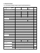
1.3 SPECIFICATIONS 1.3.1 FOR BG-101A/LT1010CR/LT121CSG/LT1210CR /LT0810CR/LT080CSG/BG-81A MODELS ITEMS BG-101A/LT1010CR LT121CSG/LT1210CR LT0810CR/LT080CSG REMARK /BG-81A POWER SUPPLY 1Ø, 115V, 60Hz COOLING CAPACITY (Btu/h) 9,800 11,500 8,000 INPUT 1,110 1,310 830 RUNNING CURRENT (A) 10.2 12.0 7.5 E.E.R 8.8 8.8 9.6 (W) (Btu/w.h) REFRIGERANT (R-22) CHARGE(g) OPERATING INDOOR (°C) TEMPERATURE OUTDOOR (°C) 470g(16.6OZ) 500g(17.6OZ) 26.7(DB) 19.4(WB) 35(DB) 23.
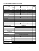
1.3.2 FOR LT1030CR/LT1230CR/BG-123A/LT1430CR MODELS LT1030CR LT1230CR/BG-123A LT1430CR ITEMS 1Ø, 230/208V, 60Hz POWER SUPPLY (Btu/h) 10,000/9,800 11,500/11,200 13,200/12,800 INPUT (W) 1,060/1,040 1,310/1,270 1,550/1,500 RUNNING CURRENT (A) 4.7/5.2 6.0/6.4 7.1/7.6 (Btu/W.h) 9.4/9.4 8.8/8.8 8.5/8.5 480g(16.9OZ) 485g(17.1OZ) 545g(19.2OZ) COOLING CAPACITY E.E.R. OPERATING TEMPERA-TURE INDOOR (°C) 26.7(DB) 19.4(WB) OUTDOOR (°C) 35(DB) 23.
1.4 FEATURES • Designed for cooling only. • Side air-intake, side cooled-air discharge. • Powerful and quiet cooling. • Top-down chassis for the simple installation and service. • Built in adjustable THERMISTOR and THERMOSTAT. • Washable one-touch filter. • Compact size. 1.5 CONTROL LOCATIONS 1.5.
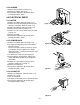
2. DISASSEMBLY INSTRUCTIONS — Prior to disassembling the unit, make sure that the POWER is off and the power cord is unplugged from the wall receptacle. 2.1 MECHANICAL PARTS 'F LOW F1 MED F2 HIGH F3 Cool y Energ Saver Fan TEMP ER POW FAN D SPEE Timer R TIME E MOD 2.1.1 FRONT GRILLE 1. Open the inlet grille downward. 2. Remove the screw which fastens the front grille. 3. Pull the front grille from the right side. 4. Remove the front grille. (See Fig. 1) 5.
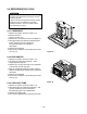
2.2 AIR HANDLING PARTS 2.2.1 ORIFICE, AND TURBO FAN 1. Remove the front grille. (Refer to section 2.1.1) 2. Remove the cabinet. (Refer to section 2.1.2) 3. Remove the 2 screws which fasten the evaporator at the left side and the right side. (See Fig. 4) 4. Move the evaporator sideward carefully. Coo Ener l Savegy r Fan F1 F2 LOW F3 MED HIGH Time r MO DE 'F TEM P TIM ER FAN SPE ED POW ER Figure 4 5. Remove the orifice. (See Fig.
2.2.3 SHROUD 1. Remove the fan. (Refer to section 2.2.2) 2. Remove the shroud. (See Fig. 9) 3. Re-install the components by referring to the removal procedures, above. 2.3 ELECTRICAL PARTS 2.3.1 MOTOR 1. Remove the cabinet. (Refer to section 2.1.2) 2. Remove the clamp cord and disconnect the wire housing in control box. (Refer to section 2.1.3) 3. Remove the turbo fan. (Refer to section 2.2.2) 4. Remove the fan. (Refer to section 2.2.2) 5. Remove the 4 or 2 screws which fasten the motor. (See Fig. 10) 6.
2.3.4 POWER CORD 1. Remove the control box. (Refer to section 2.1.3) 2. Unfold the control box. (Refer to section 2.3.3) 3. Disconnect the grounding screw from the Base pan. 4. Disconnect 2 receptacles. 5. Remove a screw which fastens the clip cord. 6. Pull the power cord. (See Fig. 13) 7. Re-install the components by referring to the removal procedure, above. (Use only one ground-marked hole, , for ground connection.) 8.
2.4 REFRIGERATION CYCLE CAUTION Discharge the refrigerant system using a FreonTM Recovery System. If there is no valve to attach the recovery system, install one (such as a WATCO A-1) before venting the FreonTM. Leave the valve in place after servicing the system. 2.4.1 CONDENSER 1. Remove the cabinet. (Refer to section 2.1.2) 2. Remove the brace. (Refer to section 2.2.1) 3. Remove the 7 screws which fasten the condenser. 4.
NOTES — Replacement of the refrigeration cycle. 1. When replacing the refrigeration cycle, be sure to discharge the refrigerant system using a FreonTM recovery System. If there is no valve to attach the recovery system, install one (such as a WATCO A-1) before venting the FreonTM. Leave the valve in place after servicing the system. 2. After discharging the unit completely, remove the desired component, and unbrace the pinch-off tubes. 3.
Equipment needed: Vacuum pump, Charging cylinder, Manifold gauge, Brazing equipment. Pinch-off tool capable of making a vapor-proof seal, Leak detector, Tubing cutter, Hand Tools to remove components, Service valve.
3. INSTALLATION 3.1 INSTALLATION REQUIREMENTS INSTALLATION HARDWARE If you use an existing wall sleeve, you should measure its dimensions. Install the new air conditioner according to these installation instructions to achieve the best performance. All wall sleeves used to mount the new air conditioner must be in good structural condition and have a compatible rear grille in order to securely attach the new air conditioner. (FIG.
3.2 INSTALLATION NOTE: All wall sleeves used to mount the new Air Conditioner must be in sound structural condition and have a rear grille that securely attaches to sleeve, or rear flange that serves as a stop for the Air Conditioner. CAUTION Installing the FRIEDRICH USC sleeve ensures optional performances of the unit. If you decide to keep the existing wall sleeve, you have to redirect the louvers at the back of the wall sleeve. Refer to FIG. 23 on p15. The use of pliers is recommended.
PROCEDURE A you are using the new sleeve (optionally 1 Ifsupplied with your unit),skip to step 3. 4 Otherwise, install the plastic grille from the kit. Cut the plastic grille to 25-1/2" wide and 15-1/4" high. Place the plastic grille to the inside of the wall sleeve at the rear flange. 5 Install the new unit into the wall sleeve. Toassembletrim,tpthetabofeachpiece into the slot of the other piece as shown below.
PROCEDURE B 1 4 Redirect the louvers at the back of the wall sleeve to 60° angle as shown in the FIG 8. The use of pliers is recommended. Remove the backing from the Vertical Insulation strip 159/16 x 13/8 x 13/8 and attach that to the inside right of the sleeve as shown below. Remove the backing from the Around Insulation strip 671/8 x 13/8 x 25/32 and attach that to the inside front of the sleeve as shown below.
PROCEDURE B CONTINUED 6 Remove the backing from the support blocks and attach them to the inside of the wall sleeve as shown FIG 29. Slide the baffle into slots of the support blocks. (7 3/32") Wall Wall Sleeve Baffle Front Support Block FIG. 29 7 Install the new unit into the wall sleeve. 8 Assemble trim as described in Step 6, Procedure A. CAUTION • Air conditioners covered in this manual pose an excessive weight hazard. Two or more people are needed to move and install the unit.
3.5 PROCEDURE C 1 4 Redirect the louvers at the back of the wall sleeve to 60° angle as shown in the FIG 30. The use of pliers is recommended. Remove the backing from the Horizontal Insulation strip 237/32 x 13/8 x 13/16 and attach that to the inside right of the sleeve as shown below. Remove the backing from the Around Insulation strip 5927/32 x 13/8 x 13/8 and attach that to the inside front of the sleeve as shown below.
PROCEDURE C CONTINUED 7 CAUTION To achieve rearward slope for unit draining, remove the backing from the 1113/16" shim strips and attach them as shown below in Fig. 37. The higher portion of shim is to be placed in front of the rib on the base of wall sleeve. 1" high 3/ " 4 High FIG. 36 • Air conditioners covered in this manual pose an excessive weight hazard. Two or more people are needed to move and install the unit.
4. TROUBLESHOOTING GUIDE 4.1 OUTSIDE DIMENSIONS 20-3/32" (499mm) 24" (610mm) Cool F1 LOW F2 MED F3 HIGH Energy Saver 'F Fan TEMP Timer TIMER FAN SPEED POWER 14-13/32" (366mm) MODE 4.2 PIPING SYSTEM CONDENSER COILS FAN CAPILLARY TUBE MOTOR COMPRESSOR TURBO FAN EVAPORATOR COILS : REFRIGERANT FLOW Following is a brief description of the important components and their functions in the refrigeration system. Refer to Fig.
4.3 TROUBLESHOOTING GUIDE In general, possible trouble is classified in two causes. The one is called Starting Failure which is caused from an electrical defect, and the other is Ineffective Air Conditioning caused by a defect in the refrigeration circuit and improper application. Unit is running but cooling is ineffective Ineffective Cooling Check cold air circulation for smooth flow. Check outdoor coil (heat exchanger) & the fan operation. Dirty indoor coil (Heat exchanger) Check gas leakage.
Fails to Start Check power source. Check circuit breaker and fuse. Check control switch setting. Gas leakage at feeler bulb of thermostat Check control switch. Only compressor fails to start. Only fan fails to start. Improper wiring. Drop in power voltage. Improper thermostat setting Defect of fan motor capacitor. Defective compressor capacitor. Loose terminal connection. Check capacitor. Irregular motor resistance ( ). Irregular motor insulation ( ). Improper wiring Replacement.
COMPLAINT Fan motor will not run. CAUSE REMEDY No power Check voltage at outlet. Correct if none. Power supply cord Check voltage to rotary switch. If none, check power supply cord. Replace cord if circuit is open. Rotary switch Check switch continuity. Refer to wiring diagram for terminal identification. Replace switch if defective. Wire disconnected or connection loose Connect wire. Refer to wiring diagram for terminal identification. Repair or replace loose terminal.
COMPLAINT Compressor will not run, but fan motor runs. CAUSE REMEDY Voltage Check voltage. See the limits on the preceding. page. If not within limits, call an electrician. Wiring Check the wire connections, if loose, repair or replace the terminal. If wires are off, refer to wiring diagram for identification, and replace. Check wire locations. If not per wiring diagram, correct. Rotary Check for continuity, refer to the wiring diagram for terminal identification.
COMPLAINT Compressor cycles on overload. Insufficient cooling or heating Excessive noise. REMEDY CAUSE Voltage Check the voltage. See the limits on the preceding page. If not within limits, call an electrician. Overload Check overload, if externally mounted. Replace if open. (If the compressor temperature is high, remove the overload, cool, and retest.) Fan motor If not running, determine the cause. Replace if required. Condenser air flow restriction Remove the cabinet.
5. SCHEMATIC DIAGRAM 5.
6.
7. REPLACEMENT PARTS LIST• MODEL: LT1030CR Location No. Part No.
• MODEL: BG-81A Location No. Part No.
• MODEL: LT0810CR Location No. Part No.
• MODEL: LT080CSG Location No. Part No.
• MODEL: BG-101A Location No. Part No.
• MODEL: LT1010CR Location No. Part No.
• MODEL: LT1210CR Location No. Part No.
• MODEL: LT121CSG Location No. Part No.
• MODEL: LT1230CR Location No. Part No.
• MODEL: LT1430CR Location No. Part No.
• MODEL: BG-123A Location No. Part No.
P/No.