C Series Micro 1Ø Input Sensorless Vector Inverter Constant Torque Sensorless/Space Vector Control 0.5 to 3HP, 200-230VAC 1Ø input, 3Ø output Installation, Operation, & Maintenance Manual CAUTION, SAFETY WARNING As with all electrical products, read manual thoroughly before operating. Only qualified, expert personnel should perform maintenance and installation.Contact the nearest authorized service facility for examination, repair, or adjustment.
SAFETY INSTRUCTIONS Always follow safety instructions to prevent accidents and potential hazards from occurring. In this manual, safety messages are classified as follows: WARNING CAUTION Improper operation may result in serious personal injury or death. Improper operation may result in personal injury or property damage. Throughout this manual we use the following two illustrations to make you aware of safety considerations: Identifies potential hazards under certain conditions.
CAUTION Do not install the drive on a flammable surface. Do not place flammable material nearby the drive. Otherwise, fire could occur. Remove the input power from the drive if a hardware failure occurs. Otherwise, it could result in a secondary accident and fire. The drive surface can emit high temperature. Be cautioned when touching. Otherwise, you may get a skin-burn. Do not apply power to a damaged inverter or to an inverter with parts missing even if the installation is complete.
(2) Wiring Do not connect a power factor correction capacitor, surge suppressor, or RFI filter to the output of the inverter. The connection orientation of the output cables U, V, W to the motor will affect the direction of rotation of the motor. Incorrect terminal wiring could result in the equipment damage. Reversing the polarity (+/-) of the terminals could damage the inverter. Only authorized personnel familiar with Cerus inverter should perform wiring and inspections.
Important User Information The purpose of this manual is to provide the user with the necessary information to install, program, start up and to maintain the C series inverter. To assure successful installation and operation, the material presented on this manual must be thoroughly read and understood before proceeding. This manual contains… Chapter Title 1 2 Basic information & precautions Installation Provides general information and precautions for safe and optimum use of the C series inverter.
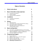
Table of Contents Table of Contents i Safety Instructions 5 1. Basic information and precautions 9 1.1 1.2 1.3 9 10 11 2. 3. 4. Installation 12 2.1 2.2 12 15 Installation precautions Dimensions Wiring 17 3.1 3.2 3.3 3.4 17 18 20 Terminal wiring Specifications for power terminal block wiring I/O terminal block specification PNP/NPN selection and connector for communication option 21 Basic configuration 23 4.1 4.2 23 4.3 5.
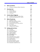
Table of Contents 6. 7. 8. 9. Basic operation 39 6.1 39 Frequency Setting and Basic Operation Function list 43 7.1 7.2 7.3 7.4 Drive Group Function Group 2 Function Group 2 I/O Group 43 44 48 53 Control block diagram 57 8.1 8.2 58 59 Frequency and Drive mode setting Accel/Decel setting and V/F control Basic Functions 60 9.1 9.2 9.3 9.4 9.5 9.6 9.
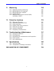
Table of Contents 11. Monitoring 11.1 11.2 11.3 11.4 11.5 100 Operating status monitoring Monitoring the I/O terminal Monitoring fault condition Analog Output Multi-function output terminal (MO) and Relay (30AC) 12. Protective functions 12.1 12.2 12.3 12.4 12.5 12.6 12.7 105 110 Electronic Thermal Overload Warning and trip Stall prevention Output phase loss protection External trip signal Inverter Overload Frequency command loss 13. Troubleshooting & Maintenance 13.1 13.2 13.3 13.4 13.
Chapter 1. Basic information & precautions 1. Basic information and precautions 1.1 Important precautions Unpacking and inspection Inspect the inverter for any damage that may have occurred during shipping. To verify the inverter unit is the correct one for the application you need, check the inverter type, output ratings on the nameplate and the inverter is intact.
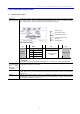
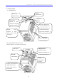
Chapter 1. Basic information & precautions 1.2 Product Details 1.2.1 Appearance Keypad Status LED Potentiometer Display Window STOP/RST Front Cover: Remove it Button when wiring and changing Body slot: When front parameter setting. cover is pulled back till this line and lifted up, it Bottom Cover: Remove wiring it when input power can be removed from main body. See Page 1-3 and motor. Inverter Nameplate 1.2.2 View without the front cover Refer to section 1-3 for front cover removal.
Chapter 1. Basic information & precautions 1.3 Removal and reinstallation 1.3.1 Removal of the front cover z To change parameter setting: Press the pattern with a finger slightly as 1) and push it downward as 2). Then 4-way button will appear. Use this button for parameter setting and changing the value. 1) 2) Side slot 1. Press here gently 4-Way Button 2. Push it down z Removal for wiring: The method is the same as shown in 1.
Chapter 1. Basic information & precautions z Removal for wiring input power and terminals: After removing the front cover, lift the bottom cover up to disconnect. Note: Input Power Terminals name is labeled here. z To access control terminals: after finishing power terminal wiring, reinstall the bottom cover and then start wiring control terminals. z Note : Use the recommended size of the cable as indicated in this manual ONLY. Using larger size cable may lead to mis-wiring or damage the insulation.
Chapter 2. Installation 2.1 Installation precautions CAUTION z Handle the inverter with care to prevent damage to the plastic components. Do not hold the inverter by the front cover. It may fall off. z Install the inverter in a place where it is immune to vibration (5.9 m/s2 or less). The inverter is under great influence of ambient temperature z Install in a location where temperature is within the permissible range (14~122°F/-10~50°C).
Chapter 2. Installation z When two or more inverters are installed or a ventilation fan is mounted in inverter panel, the inverters and ventilation fan must be installed in proper positions with extreme care taken to keep the ambient temperature of the inverters below the permissible value. If they are installed in improper positions, the ambient temperature of the inverters will rise and ventilation effect will be reduced.
Chapter 2. Installation 2.2 Dimensions z 0.4, 0.75 kW (1/2~1 HP) W H D mm (inch) Dimension CI-000-C2-1P CI-001-C2-1P CI-002-C2-1P CI-003-C2-1P W 79 (3.11) 79 (3.11) 156(6.14) 156(6.14) H 143(5.63) 143(5.63) 143(5.63) 143(5.63) D 143(5.63) 143(5.63) 143(5.63) 143(5.63) Weight Kg (lbs) 0.95(2.09) 0.97(2.14) 1.94(4.28) 2(4.
Chapter 2. Installation z 1.5, 2.2 kW (2~3HP) W H D mm (inch) Dimension CI-000-C2-1P CI-001-C2-1P CI-002-C2-1P CI-003-C2-1P W 79 (3.11) 79 (3.11) 156(6.14) 156(6.14) H 143(5.63) 143(5.63) 143(5.63) 143(5.63) D 143(5.63) 143(5.63) 143(5.63) 143(5.63) Weight Kg (lbs) 0.95(2.09) 0.97(2.14) 1.94(4.28) 2(4.
Chapter 3. Wiring 3. Wiring 3.
Chapter 3. Wiring 3.2 Specifications for power terminal block wiring CI-000-C2-1P L1 L2 CI-001-C2-1P P P1 CI-002-C2-1P N L1 U CI-003-C2-1P V L2 P P1 N U V Input wire size Output wire 2mm2 2mm2 2mm2 2mm2 3.5mm2 3.5mm2 3.5mm2 3.5mm2 Ground Wire 2mm2 2mm2 3.5mm2 3.5mm2 Terminal Lug 2mm2 ,3.5 φ 2mm2 ,3.5 φ 3.5mm2 ,3.5 φ 3.5mm2,3.5 φ 13kgf cm 13kgf cm 15kgf cm 15kgf cm Tightening Torque W W CAUTION z z z z z z z Make sure the input power is off before wiring.
Chapter 3. Wiring WARNING z z Use the Type 3 grounding method (Ground impedance: Below 100ohm). Use the dedicated ground terminal to ground the inverter. Do not use the screw in the case or chassis, etc. for grounding. Dedicated Terminal Ground Dedicated Terminal Ground Note: Remove front and bottom cover before starting grounding. Caution: Follow the specifications below when grounding the inverter.
Chapter 3. Wiring 3.3 I/O terminal block specification Terminal P1/P2/P3 P4/P5 Terminal Description Multi-function input T/M P1-P5 Wire size 22 AWG, 0.3 mm2 Torque (Nm) 0.4 CM Common Terminal for P1-P5, AM, P24 12V power supply for external potentiometer 0-10V Analog Voltage input 22 AWG, 0.3 mm2 0.4 22 AWG, 0.3 mm2 0.4 22 AWG, 0.3 mm2 0.4 2 VR V1 I 0-20mA Analog Current input 22 AWG, 0.3 mm 0.4 AM Multi-function Analog output 22 AWG, 0.3 mm2 0.
Chapter 3. Wiring 3.4 PNP/NPN selection and connector for communication option S4 1. When using P24 [NPN] 24X 24I CM Resistor FX Resistor CPU Resistor CM CM S4 2. When using 24V external power 24X 24I CM Resistor supply [PNP] FX Resistor CPU Resistor CM CM 2. Communication Option Card Connector: Install Communication option card here. Note: MODBUS RTU option card is available for C series. Refer to C series MODBUS RTU option manual for more details.
Chapter 3.
Chapter 4 - Basic configuration 4.1 Connection of peripheral devices to the inverter The following devices are required to operate the inverter. Proper peripheral devices must be selected and correct connections made to ensure proper operation. An incorrectly applied or installed inverter can result in system malfunction or reduction in product life as well as component damage. You must read and understand this manual thoroughly before proceeding.
Chapter 4 - Basic configuration 4.2 4.3 Recommended MCCB, Earth leakage circuit breaker (ELB) and Magnetic contactor specification Model MCCB/ ELB(LG) Magnetic Contactor CI-000-C2-1P CRS33b, EBS333 CRC-12 CI-001-C2-1P CRS33b, EBS333 CRC-18 CI-002-C2-1P CRS33b, EBS333 CRC-25 CI-003-C2-1P CRS33b, EBS333 CRC-32 Note Recommendable AC/DC Reactor Model AC input fuse AC reactor DC reactor CI-000-C2-1P 10A 2.13mH, 5.7A 7.00mH, 5.4A CI-001-C2-1P 20A 1.20mH, 10A 4.05mH, 9.
Chapter 5. Programming keypad 5. Programming Keypad 5.
Chapter 5. Programming keypad 5.
Chapter 5. Programming keypad 5.3 Moving to other groups z There are 4 different parameter groups as shown below. Drive group Function group 1 Function group 2 I/O group Drive group Function group 1 Function group 2 I/O (Input/Output) group z Basic parameters necessary for the inverter to run. Parameters such as Target frequency and Accel/Decel time are settable. Basic function parameters to adjust output frequency and voltage.
Chapter 5. Programming keypad z How to move to other groups at the 1st code of each group. 1 -. The 1st code in Drive group “0.0” will be displayed when AC input power is applied. -. Press the right arrow (X) key once to go to Function group 1. 2 -. The 1st code in Function group 1 “F 0” will be displayed. -. Press the right arrow (X) key once to go to Function group 2. 3 -. The 1st code in Function group 2 “H 0” will be displayed. -. Press the right arrow (X) key once to go to I/O group. 4 -.
Chapter 5. Programming keypad 5.4 How to change the codes in a group z Code change in Drive group -. In the 1st code in Drive group “0.0”, press the Up (S) key once. 1 -. The 2nd code in Drive group “ACC” is displayed. -. Press the Up (S) key once. -. The 3rd code “dEC” in Drive group is displayed. -. Keep pressing the Up (S) key until the last code appears. 2 3 Drive group 4 -. The last code in Drive group “drC” is displayed. -. Press the Up (S) key again. 5 -.
Chapter 5. Programming keypad z For changing code from any codes other than F 0 When moving from F 1 to F 15 in Function group 1. 1 -. In F 1, continue pressing the Up (S) key until F15 is displayed. 2 -. Moving to F15 has been complete. ♣ The same rule applies to Function group 2 and I/O group. ♣ Note: Some codes will be skipped in the middle of increment (S)/decrement (T) for code change.
Chapter 5. Programming keypad 5.5 Parameter setting method z Changing parameter value in Drive group When changing ACC time from 5.0 sec to 16.0 Drive group 1 -. In the first code “0.0”, press the Up (S) key once to go to the second code. 2 -. ACC [Accel time] is displayed. -. Press the Prog/Ent key (z) once. 3 -. Preset value is 5.0, and the cursor is in the digit 0. -. Press the Left (W) key once to move the cursor to the left. 4 -. The digit 5 in 5.0 is active. Then press the Up (S) key once.
Chapter 5. Programming keypad When changing run frequency to 30.05 Hz in Drive group Drive group 1 -. In “0.0”, press the Prog/Ent (z) key once. 2 -. The second 0 in 0.0 is active. -. Press the Right (X) key once to move the cursor to the right. 3 -. 0.00 is displayed -. Press the Up (S) key until 5 is displayed. 4 -. Press the Left (W) key once. 5 -. The middle digit in 0.05 is active. -. Press the Left (W) key once. 6 -. Press the Left (W) key once. 7 8 9 -. 00.
Chapter 5. Programming keypad z Changing parameter values in Function 1, 2 and I/O group When changing the parameter value of F 27 from 2 to 5 Function group 1 1 -. In F0, press the Prog/Ent (z) key once. 2 -. Check the present code number. -. Increase the value to 7 by pressing the Up (S) key. 3 -. When 7 is set, press the Left (W) key once. 4 -. 0 in 07 is active. -. Increase the value to 2 by pressing the Up (S) key. 5 -. 27 is displayed -. Press the Prog/Ent (z) key once. 6 -.
Chapter 5. Programming keypad 5.6 Monitoring of operation status Monitoring output current in Drive group Drive group 1 -. In [0.0], continue pressing the Up (S) or Down (T) key until [Cur] is displayed. 2 -. Monitoring output current is provided in this parameter. -. Press the Prog/Ent (z) key once to check the current. 3 -. Present output current is 5.0 A. -. Press the Prog/Ent (z) key once to return to the parameter name. 4 -. Return to the output current monitoring code.
Chapter 5. Programming keypad How to monitor Motor rpm in Drive group when the motor is rotating in 1730 rpm. Drive group 1 -. Present run frequency can be monitored in the first code of Function group 1. The preset frequency is 57.6Hz. -. Continue pressing the Up (S) /Down (T) key until rPM is displayed. 2 -. Motor rpm can be monitored in this code. -. Press the Prog/Ent (z) key once. 3 -. Last three digits 730 in 1730 rpm is shown on the LED. -. Press the Left (W) key once. 4 -.
Chapter 5. Programming keypad How to monitor fault condition in Drive group During Accel Overcurrent trip Current Frequency Drive group STOP/RST 1 -. This message appears when an Overcurrent fault occurs. -. Press the Prog/Ent (z) key once. 2 -. The run frequency at the time of fault (30.0) is displayed. -. Press the Up (S) key once. 3 -. The output current at the time of fault is displayed. -. Press the Up (S) key once. 4 -. Operating status is displayed. A fault occurred during acceleration.
Chapter 5. Programming keypad Parameter initialize z How to initialize parameters of all four groups in H93 Function group 2 1 -. In H0, press the Prog/Ent (z) key once. 2 -. Code number of H0 is displayed. -. Increase the value to 3 by pressing the Up (S) key. 3 -. In 3, press the Left (W) key once to move the cursor to the left. 4 -. 03 is displayed. 0 in 03 is active. -. Increase the value to 9 by pressing the Up (S) key. 5 -. 93 is set. -. Press the Prog/Ent (z) key once. 6 -.
Chapter 5.
Chapter 6. Basic operation CHAPTER 6 6.1 Basic operation Frequency Setting and Basic Operation Caution : The following instructions are given based on the fact that all parameters are set to factory defaults. Results could be different if parameter values are changed. In this case, initialize parameter values (see page 10-17) back to factory defaults and follow the instructions below. Frequency Setting via keypad & operating via terminals 1 -. Apply AC input power to the inverter. 2 -. When 0.
Chapter 6. Basic operation Frequency Setting via potentiometer & operating via terminals 1 -. Apply AC input power to the inverter. 2 -. When 0.0 appears Press the Up (S) key four times. -. Frq is displayed. Frequency setting mode is selectable. -. Press the Prog/Ent (z) key once. -. Present setting method is set to 0 (frequency setting via keypad). -. Press the Up (S) key twice. 3 4 -. After 2 (Frequency setting via potentiometer) is set, press the Prog/Ent (z) key once. 5 -.
Chapter 6. Basic operation Frequency setting via potentiometer & operating via the Run key 1 -. Apply AC input power to the inverter. 2 -. When 0.0 is displayed, press the Up (S) key three times. -. drv is displayed. Operating method is selectable. -. Press the Prog/Ent (z) key. -. Check the present operating method (“1” is run via control terminal) -. Press the Prog/Ent (z) key and then Down (T) key once. 3 4 5 -. After setting “0”, press the Prog/Ent (z) key. -.
Chapter 6.
Chapter 7. Function list CHAPTER 7 - Function list Drive Group LED display 0.
Chapter 7. Function list Function group 1 LED display F0 Parameter name [Jump code] Min/Max range 0/60 F1 [Forward/ Reverse run disable] [Accel pattern] [Decel pattern] [Stop mode select] 0/2 F2 F3 F4 0/1 0/2 Description This parameter sets the parameter code number to jump.
Chapter 7.
Chapter 7.
Chapter 7.
Chapter 7. Function list 1) Set H10 to 1 to be displayed. # H17, 18 is used when F2, F3 is set to 1 S-Curve. Function group 2 LED display H22 2) Parameter name [Speed Search Select] Min/Max range 0/15 Description This parameter is active to prevent any possible fault when the inverter outputs its voltage to the running motor. Factory defaults 0 Adjustable during run O 100 O 100 O 1000 O Page 1012 1. H20- 2.Restart 3.Operation 4.
Chapter 7. Function list Function group 2 LED display H31 H32 Parameter Name [Number of motor poles] [Rated slip frequency] Min/Max Range 2/12 0/10 [Hz] Description This setting is displayed via rPM in drive group. ⎛ rpm × P ⎞ fs = fr − ⎜ ⎟ ⎝ 120 ⎠ Where, f s = Rated slip frequency Factory defaults - Adjustable during run X Page X 2) Automatically set f r = Rated frequency rpm = Motor nameplate RPM H33 H34 H36 H37 [Motor rated current] [No Load Motor Current] 1.0/20 [A] 0.
Chapter 7. Function list Function group 2 LED display H51 Parameter Name [P gain for PID controller] [Integral time for PID controller (I gain)] Differential time for PID controller (D gain) F gain for PID controller [PID output frequency limit] Min/Max Range 0/999.9 [%] 0.1/32.
Chapter 7.
Chapter 7.
Chapter 7.
Chapter 7.
Chapter 7. Function list I/O group LED display Parameter name Min/Max range Factory defaults Adjustable during run This parameter is set when the inverter uses RS485 communication. 1 O Select the Baud rate of the RS485 1200 bps 2400 bps 4800 bps 9600 bps 19200 bps It is used when frequency command is given via V1 and I terminal or communication option.
Chapter 7.
Chapter 8.
P5 P4 P3 P2 P1 I V1 VR : Potentiometer Digital input filter I/O group I27 Analog input filter I/O group I 1, 6, 11 0,1 17 I20 ~ I24 I20 ~ I24 Step 0-7 3-Wire operation I/O group Max/Min frequency Functi group on 1 F21 F23 I30 I31 I32 I33 I/O group St1 St2 St3 I/O group Step freq.
P5 P4 P3 P2 P1 I/O group 5,6,7 I20 ~ I24 I/O group Digital input filter I27 Multi-Accel/Decel time select 59 F29 F28 Torque boost value Func. group F31~F38 Func. group User V/F Freq., Voltage I34 ~ I47 1st-7th Accel/ Decel time I/O group ACC DEC 0 1~7 Max freq. Automatic Manual User V/F Square Linear P1 ~ P5 1 0 F27 Func. group Torque boost select 2 1 0 F2, F3 Func. group V/F pattern Frequency setting 1 0 H70 Reference freq. for Accel/Decel Func.
Chapter 9. Basic functions CHAPTER 9 9.1 z Frequency mode Digital Frequency setting via Keypad 1 Group Drive group z Basic Functions LED Display Parameter Name Set Value Min/Max Range Factory Defaults Unit Hz 0.0 [Frequency Command] - 0/400 0.0 Frq [Frequency mode] 0 0/8 0 Run frequency is settable in 0.0 - [Frequency Command]. Set Frq – [Frequency mode] to 0 {Frequency setting via Keypad 1}. Set the desired frequency in 0.
Chapter 9. Basic functions z Analog Frequency setting via Potentiometer (V0) on the Keypad Used to prevent fluctuations in analog input signals caused by noise. Group Drive group I/O group LED Display Set Value Min/Max Range Factory Defaults Unit Hz 0.
Chapter 9. Basic functions z Analog Frequency setting via Voltage analog input (0-10V) or potentiometer on the VR terminal Group Drive group I/O group LED Display Set Value Min/Max Range Factory Defaults Unit Hz 0.0 [Frequency command] - - - Frq 3 0/8 0 10 0/9999 10 - 0/10 0 V I8 [Frequency mode] [Filtering time constant for V1 input] [V1 input minimum voltage] [Frequency corresponding to I 7] - 0/400 0.
Chapter 9. Basic functions z Frequency setting via Potentiometer on the keypad + Current Analog input (0-20mA) Group Drive group LED Display Parameter Name Set Value Min/Max Range Factory Defaults Unit Hz 0.0 [Frequency Command] - - - Frq [Frequency Mode] 5 0/8 0 Select Frq – [Frequency Mode] to 5 {Potentiometer on the keypad and Current Analog input (020mA)}. Override function is provided via Main speed and Auxiliary speed adjustment.
Chapter 9. Basic functions z Analog Hold Group Drive group I/O group LED Display Parameter Name Frq [Frequency Mode] I20 [Multi-function terminal P1 define] input ~ ~ I24 [Multi-function input Terminal P5 Define] Set Value Min/Max Range Factory Defaults 2/7 0/8 0 - 0/24 23 0 4 This setting becomes activated when Frq – [Frequency Mode] is set to 2-7. Set one of the Multi-function input terminals to 23 to activate Analog Hold operation.
Chapter 9. Basic functions 9.2 Multi-Step frequency setting Group Drive group I/O group LED Display Parameter Name Set Value Min/Max Range Factory Defaults Unit 5.0 0/400 0.0 Hz 0/8 0 - 0.0 [Frequency command] Frq [Frq mode] 0 St1 [Multi-Step frequency 1] - St2 [Multi-Step frequency 2] - St3 [Multi-Step frequency 3] - 30.
Chapter 9. Basic functions 9.3 z Run Command setting Run via the Run and STOP/RST key Group LED Display Drive group Parameter Name drv [Drive mode] (Run/Stop mode) drC [Direction of rotation select] motor Set Value Min/Max Range Factory Defaults 0 0/3 1 - F/r F Unit Set drv – [Drive mode] to 0. Motor starts to accelerate by pressing the Run key while run frequency is set. Motor decelerates to stop by pressing the STOP/RST key.
Chapter 9. Basic functions z Run command setting 2 at FX and RX terminals Group Drive group I/O group LED Display drv I20 I21 Parameter Name [Drive mode] (Run/Stop mode) [Multi-function terminal P1 define] [Multi-function terminal P2 define] input input Set Value Min/Max Range Factory Defaults 2 0/3 1 0 0/24 0 1 0/24 1 Unit Set the drv to 2. Set I20 and I21 to 0 and 1 to use P1 and P2 as FX and RX terminals. FX: Run command setting.
Chapter 9. Basic functions z Power On Start select Group LED Display Parameter Name Drive group drv [Drive mode] (Run/Stop mode) Function group 2 H20 [Power On Start select] Set Value Min/Max Range Factory Defaults 1, 2 0/3 1 1 0/1 0 Unit Set H20 to 1. When AC input power is applied to the inverter with drv set to 1 or 2 {Run via control terminal} ON, motor starts acceleration. This parameter is inactive when the drv is set to 0 {Run via keypad}.
Chapter 9. Basic functions z Restart after fault reset Group LED display Parameter name Drive group Drv [Drive mode] (Run/Stop mode) Function group 2 H21 [Restart after fault reset] Set value Min/Max range Factory defaults 1, 2 0/3 1 1 0/1 0 Unit Set H21 to 1. Motor starts acceleration if drv is set to 1 or 2 and the selected terminal is ON when a fault is cleared. This function is inactive when the drv is set to 0 {Run via the Keypad}.
Chapter 9. Basic functions 9.4 z Accel/Decel time and unit setting Accel/Decel time setting based on Max frequency Group LED Display Drive group Function group 1 Function group 2 Parameter Name Set Value Min/Max Range Factory Defaults Unit ACC [Accel time] - 0/6000 5.0 sec dEC [Decel time] - 0/6000 10.0 sec F21 [Max frequency] - 0/400 60.
Chapter 9. Basic functions z Accel/Decel time based on Run frequency Group Drive group Function group 2 LED display Parameter name Set value Min/Max range Factory defaults Unit ACC [Accel time] - 0/6000 5.0 sec dEC [Decel time] - 0/6000 10.0 sec H70 [Frequency reference for Accel/Decel] 1 0/1 0 Accel/Decel time is set at the ACC/dEC. If you set H70 to 1 {Delta frequency}, Accel/Decel time is the time that takes to reach a target freq from run freq (Currently operating freq.).
Chapter 9. Basic functions z Multi-Accel/Decel time setting via Multi-function terminals Group LED Display Drive group I/O group Parameter Name Min/Max Range Factory Defaults Unit ACC [Accel time] - 0/6000 5.0 Sec dEC [Decel time] - 0/6000 10.
Chapter 9. Basic functions z Accel/Decel pattern setting Group LED display Function group 1 F2 [Accel pattern] F3 [Decel pattern] [S-Curve start side] [S-Curve end side] H17 Function group 2 H18 Min/Max range Set value 0 Linear 0 1 S-curve Parameter name accel/decel accel/decel Unit 40 % 40 % 1~100 Accel/Decel pattern is settable at F2 and F3.
Chapter 9. Basic functions z Note that setting Frequency Ref. for Accel/decel (H70) is set to Max Freq and target freq is set below Max freq. the shape of S-curve may be distorted. Accel/decel Ref Freq (H70) Note: If set target freq is below Max freq, the Target Freq curve will not be shown completely.
Chapter 9. Basic functions 9.5 z V/F control Linear V/F operation Group LED Display Parameter Name Set Value Min/Max Range Factory Defaults Unit Function group 1 F22 [Base frequency] - 30/400 60.0 Hz F23 [Start frequency] - 0/10.0 0.5 Hz F30 [V/F pattern] 0 0/2 0 Set F30 to 0 {Linear}. This pattern maintains a linear Volts/frequency ratio from F23 - [Start frequency] to F22- [Base frequency]. This is appropriate for constant torque applications.
Chapter 9. Basic functions 9.6 z Stop mode select Decel to stop Group Function group 1 LED Display F4 Parameter Name [Stop mode select] Set Value Min/Max Range Factory Defaults 0 0/2 0 Set Value Min/Max Range Factory Defaults 1 0/2 0 Set Value Min/Max Range Factory Defaults 2 0/2 0 Unit Set F30 to 0 {Decel to stop}. The inverter decelerates to 0Hz for the preset time. Freq.
Chapter 9. Basic functions 9.7 z Frequency limit setting Frequency limit setting based on Max and start frequency Set Group LED display Parameter name value Function F21 [Max frequency] group 1 F23 [Start frequency] Min/Max range Factory defaults Unit 0/400 60.0 Hz 0/10 0.5 Hz Max frequency: Frequency high limit except for F22 [Base frequency]. Any frequency cannot be set above [Max frequency]. Start frequency: Frequency low limit. If a frequency is set lower than this, 0.
Chapter 9. Basic functions z Skip frequency Group Function group 2 LED display Parameter name Set value Min/Max range Factory defaults Unit H10 [Skip frequency select] 1 0/1 0 H11 [Skip frequency low limit 1] - 0/400 10.0 Hz ~ ~ H16 [Skip frequency high limit 3] - 0/400 35.0 Hz Set H10 to 1. Run frequency setting is not available within the skip frequency range of H11-H16. Skip frequency is settable within the range of F21 – [Max frequency] and F23 – [Start frequency].
Chapter 10. Advanced functions 10. Advanced functions 10.1 DC brake z Stop mode via DC brake Set value Min/Max Range Factory Defaults 1 0/2 0 - 0/60 5.0 Hz [DC Brake wait time] - 0/60 0.1 sec F10 [DC Brake voltage] - 0/200 50 % F11 [DC Brake time] - 0/60 1.0 sec Group LED Display Function group 1 F4 [Stop mode select] F8 [DC Brake frequency] F9 Parameter Name start Unit Set F4 - [Stop mode select] to 1.
Chapter 10. Advanced functions z Starting DC brake Group LED Display Parameter Name Set value Min/Max Range Factory Defaults Unit Function group 1 F12 [DC Brake start voltage] - 0/200 50 % F13 [DC Brake start time] - 0/60 0 sec F12: It sets the level as a percent of H33 – [Motor rated current]. F13: Motor accelerates after DC voltage is applied for the set time.
Chapter 10. Advanced functions 10.2 Jog operation Group Function group 1 I/O group LED display Parameter name Set value Min/Max range Factory defaults Unit Hz F20 Jog frequency - 0/400 10.0 I22 [Multi-function input terminal P3 define] 4 0/24 2 Set the desired jog frequency in F20. Select the terminal among the Multi-function input terminal P1 thru P5 to use for this setting. If P3 is set for Jog operation, set I22 to 4 {Jog}.
Chapter 10. Advanced functions 10.3 Up-Down operation Group I/O group LED display I20 ~ I23 I24 Set value Parameter name [Multi-function terminal P1 define] input Min/Max range 0 Factory defaults 2 ~ [Multi-function input terminal P4 define] [Multi-function input terminal P5 define] 0/24 15 3 16 4 Select terminals for Up-Down operation among P1 thru P5. If P4 and P5 are selected, set I23 and I24 to 15 {Frequency Up command} and 16 {Frequency Down command}, respectively.
Chapter 10. Advanced functions 10.4 3-Wire Operation Group LED display I/O group I20 Set value Parameter name [Multi-function terminal P1 define] input Min/Max range 0 Factory defaults Unit 2 0/24 ~ ~ I24 [Multi-function input terminal P5 define] 17 4 Select the terminal among P1 thru P5 for use as 3-Wire operation. If P5 is selected, set I24 to 17 {3-Wire operation}.
Chapter 10. Advanced functions 10.5 Dwell operation Group LED Display Function group 2 Parameter Name Set value Min/Max Range Factory Defaults Unit H7 [Dwell frequency] - 0/400 5.0 Hz H8 [Dwell time] - 0/10 0.0 sec In this setting, motor begins to accelerate after dwell operation is executed for dwell time at the dwell frequency. It is mainly used to release mechanical brake in elevators after operating at dwell frequency.
Chapter 10. Advanced functions 10.6 Slip compensation Set value Min/Max Range Factory Defaults [Motor type select] - 0.2/2.2 - H31 [Number of motor poles] - 2/12 4 H32 [Rated slip frequency] - 0/10 - Hz H33 [Motor rated current] - 1.0/12 - A H34 [Motor No Load Current] - 0.
Chapter 10. Advanced functions Example Rated frequency= 60Hz Rated motor RPM= 1740rpm Motor pole number= 4 ⎛ 1740 × 4 ⎞ f s = 60 − ⎜ ⎟ = 2 Hz ⎝ 120 ⎠ H32- [Rated slip frequency] is 2Hz. Set H32- [Rated slip frequency] to 2. H33: Enter the motor nameplate rated current H34: Enter the measured current when the motor is running at rated frequency after the load is removed. Enter 50% of the rated motor current when it is difficult to measure the motor no load current.
Chapter 10. Advanced functions 10.7 PID Control Set value Min/Max Range Factory Defaults Unit [Control mode select] 2 0/3 0 - H50 [PID Feedback select] - 0/1 0 - H51 [P gain for PID controller] - 0/999.9 300.0 % - 0.1/32.0 300 Sec - 0.0/30.0 0 Sec 0/999.9 0 % - 0/400 60.
2 I 2 ~ I15 I 1, 6, 11 I : 0 ~ 20mA 4 1 I 7 ~ I15 I 1, 6, 11 V 1 H50 I/O group I/O group 0 Func. group2 Analog input scale Analog input filter Feedback select V1 : 0 ~ 10V 3 2 V0:Potentiometer 1 Keypad setting 2 0 Keypad setting 1 4 3 1 I/O group I/O group 0 Analog input scale Analog input filter Frq DRV group Ref. freq setting I I V0 : Potentiometer V 1 Keypa settin d g + H53 : D time H51 : P Gain H52 :I time Func. group2 PID Control H54 Func.
10. Advanced functions 10.8 Auto tuning Set value Min/Max Range Factory Defaults Unit [Auto tuning] 1 0/1 0 - H42 [Stator resistance (Rs)] - 0/14.0 - Ω H44 [Leakage (Lσ)] - 0/300.00 - mH Group LED Display Function group 2 H41 Parameter Name inductance Automatic measuring of the motor parameters is provided. The measured motor parameters in H41 can be used in Auto Torque Boost and Sensorless Vector Control. CAUTION: Auto tuning should be executed after stopping the motor.
10. Advanced functions 10.9 Sensorless vector control Group LED Display Function group 2 H40 H30 Min/Max Range Factory Defaults Unit [Control mode select] 3 0/3 0 - [Motor type select] - 0.2/2.2 - kW - 0/10 - Hz - 1.0/12 - A H33 [Rated slip frequency] [Motor rated current] H34 [Motor No Load Current] - 0.1/12 - A H42 [Stator resistance (Rs)] - 0/14.0 - Ω - 0/300.00 - mH - 0.0/60.0 1.
10. Advanced functions Factory default of motor parameters (Function group 2) H30-Motor rating [kW] H32-Rated slip freq [Hz] H33-Current rating [A] H34-No-load current [A] H42-Stator resistance [Ω] H44-Leakage inductance [mH] 0.2 0.9 0.5 3.0 14.0 122.0 0.4 1.8 1.1 3.0 6.7 61.58.893 0.75 3.5 2.1 2.33 2.46 28.14 1.5 6.5 3.5 2.33 1.13 14.75 2.2 8.8 4.4 2.0 0.869 11.31 10.
10. Advanced functions 10.
10. Advanced functions H23: It limits the current during Speed search. Set as the percent of H33 – [Motor rated current]. H24, H25: Speed search is activated via PI control. Adjust P gain and I gain corresponding to the load characteristics. I54, I55: Signal of active Speed search is given to external sequence via Multi-function output terminal (MO) and Multi-function relay output (30AC).
10. Advanced functions 10.12 Auto restart try Group LED Display Function group 2 H26 H27 Parameter Name Set value Min/Max Range Factory Defaults - 0/10 0 - 0/60 1.0 [Number of Auto Restart try] [Auto Restart time] Unit Sec This parameter sets the number of times auto restart is activated in H26. It is used to prevent the system down caused by internal protection function activated by the causes such as noise. H26: Auto restart will become active after the H27.
10. Advanced functions 10.13 Carrier frequency select Group LED Display Function group 2 H39 Parameter Name [Carrier select] Set value Min/Max Range Factory Defaults - 0/15 10 frequency Unit This parameter affects the sound of the inverter during operation. H39 If carrier frequency set higher Motor noise v Heat loss of the inverter u Inverter noise u Leakage current u 10.
10. Advanced functions 2nd motor operation does not run 2 motors at the same time. As the figure below, when using two motors with an inverter by exchanging them, different values can be set for the 2nd motor via the Multi-function input terminal and parameters set in H81H90. Turn the I24 (setting: 12) On after motor is stopped. Parameters from H81 to H90 are applied to the 1st motor as well as the 2nd motor. Motor 1 SV-iC5 C series Motor 2 P5 10.
10. Advanced functions z Password Register Group LED Display Function group 2 Parameter Name Set value Min/Max Range Factory Defaults H94 [Password Register] - 0/FFF 0 H95 [Parameter lock] - 0/FFF 0 Unit This parameter creates password for H95 – [Parameter lock]. Valid password is Hex decimal value (0-9, A, B, C, D, E, F). CAUTION: Do not forget the registered password. It is also used when unlocking the parameters. Factory default password is 0. Enter the new password except 0.
10. Advanced functions z Parameter Lock Group Function group 2 LED Display H95 [Parameter lock] - Min/Max Range 0/FFF H94 [Password Register] - 0/FFF Parameter Name Set value Factory Defaults Unit 0 0 This parameter is used to lock the user-set parameters using the password. See the table below to lock the user-set parameter via the H94 – [Password Register].
10.
Chapter 11. Monitoring 11. Monitoring 11.1 Operating status monitoring z Output current Group LED Display Set value Description Drive CUr Output current group Inverter output current can be monitored in Cur.
Chapter 11. Monitoring z User display select LED Display Group Drive group Function group 2 vOL H73 Set value Parameter Name [User display select] Min/Max range Factory default 0/2 0 Unit - [Monitoring item select] - The selected item in H73- [Monitoring item select] can be monitored in vOL- [User display select]. H73: Select one of the desired item numbers.
Chapter 11. Monitoring 11.2 Monitoring the I/O terminal z Input terminal status monitoring Group I/O group LED Display I25 Set value Parameter Name [Input terminal display] status Min/Max range Factory default Unit - Active input terminal status (ON/OFF) can be monitored in I25. The following is displayed when P1, P3, P4 are ON and P2, P5 are OFF.
Chapter 11. Monitoring 11.3 Monitoring fault condition z Monitoring fault display Group Drive group LED Display nOn Set value Parameter Name [Fault Display] Min/Max range Factory default Unit - The kind of fault occurred during operation is displayed in nOn. Up to 3 kinds of faults can be monitored. This parameter gives information on fault types and the operating status at the time of the fault. Refer to 1.6 How to monitor operation. Refer to Page 13-1 for various fault types.
Chapter 11. Monitoring Fault type Operating status when a fault occurs 11.4 Analog Output LED Display Group I/O group I50 I51 Parameter Name [Analog output select] [Analog output adjustment] item level Set value Min/Max range Factory default - 0/3 0 - 10/200 100 Unit % Output item and the level from the AM terminal are selectable and adjustable. I50: The selected item will be output to Analog output terminal (AM). I50 Analog output item select 10V 0 Output frequency.
Chapter 11. Monitoring 11.
Chapter 11. Monitoring I56: When 17 {Fault display} is selected in I54 and I55, Multi-function output terminal and relay will be activated with the value set in I56. 0: FDT-1 Check whether the output frequency of the inverter matches the user-setting frequency.
Chapter 11. Monitoring 2: FDT-3 It activates when run frequency meets the following condition. Active condition: Absolute value (FDT level - run frequency) <= FDT Bandwidth/2 Group I/O group LED Display I52 I53 Set value Parameter Name [Frequency level] [Frequency Bandwidth] Detection Min/Max range Factory default 30.0 0/400 Detection Unit Hz 10.0 - It cannot be set above F21- [Max frequency]. When setting I52 and I53 to 30.0Hz and 10.0 Hz, respectively 35Hz 30Hz 25Hz Freq.
Chapter 11. Monitoring Decel time: Run Frequency > (FDT Level – FDT Bandwidth/2) LED Display Group I/O group I52 I53 Set value Parameter Name [Frequency Level] [Frequency Bandwidth] Detection Detection Min/Max range Factory default Unit 30.0 0/400 Hz 10.0 - It cannot be set above F21- [Max Frequency]. When setting I52, I53 to 30.0 Hz and 10.0Hz, respectively 30Hz 25Hz Freq.
Chapter 11. Monitoring 12: During run Become active when run command is given and the inverter generates output voltage. Freq. MO Run command 13: During stop Activated during stop. Freq. MO Run command 14: During constant run Activated during nominal operation. Freq. MO Run command 15: During speed searching Refer to Page 10-12 Speed search operation.
Chapter 12. Protective functions 12.1 Electronic Thermal Group LED display Function group 1 F50 F51 F52 F53 Parameter Name [Electronic thermal select] [Electronic thermal level for 1 minute] [Electronic thermal level for continuous] [Motor type] Set value Min/Max setting Factory default 1 0/1 0 - Unit 150 % 100 % 50/150 - 0/1 0 Select F50 – [Electronic thermal select] to 1. It activates when the motor is overheated (time-inverse).
Chapter 12. Protective functions 12.2 Overload Warning and trip z Overload warning LED Group Display Function F54 group 1 F55 I/O group I54 I55 Parameter Name [Overload warning level] [Overload warning time] [Multi-function output terminal select] [Multi-function relay select] Set value Min/Max setting Factory default Unit - 30/150 150 % - 0/30 10 Sec 5 0/17 12 5 17 Select one output terminal for this function between MO and 30AC.
Chapter 12. Protective functions 12.3 Stall prevention Group LED Display Parameter Name Set value Min/Max setting Factory default Function group 1 F59 [Stall prevention select] - 0/7 3 F60 [Stall prevention level] - 30/150 150 I54 [Multi-function output terminal select] 7 I55 [Multi-function relay select] 7 I/O group 0/17 Unit % 12 17 During acceleration: Motor acceleration is stopped when current exceeding the value set in F60 flows.
Chapter 12. Protective functions F60 Current Freq. Multi-functi on output or relay t1 During acceleration t2 During constant run DC voltage Freq. Multi-function output or relay During deceleration 12.4 Output phase loss protection Group LED display Parameter Name Set value Min/Max setting Factory default Function group 2 H19 [Output phase loss protection select] 1 0/1 0 Unit Set H19 value to 1.
Chapter 12. Protective functions 12.5 External trip signal Group I/O group LED display Description I20 [Multi-function input terminal P1 define] ~ ~ I23 I24 Set Value Min/Max setting Factory default Unit 0 0/24 [Multi-function input terminal P4 define] [Multi-function input terminal P5 define] 18 3 19 4 Select a terminal among P1 thru P5 to output external trip signal. Set I23 and I24 to 18 and 19 to define P4 and P5 as External A contact and B contact.
Chapter 12. Protective functions 12.6 Inverter Overload Inverter overload prevention function is activated when the current above inverter rated current flows. Multi-function output terminal (MO) or Multi-function relay (30AC) is used as the alarm signal output during inverter overload trip. Group I/O group LED display I54 I55 Set value Parameter Name [Multi-function output terminal select] [Multi-function relay select] Min/Max Range 7 Factory default Unit 12 0/17 7 17 12.
Chapter 12. Protective functions I62: When no frequency command is given for the time set in I63, set the drive mode as the table below. I62 [Drive mode 0 select after loss of frequency 1 command] 2 Continuous operation with the frequency before command loss occurs Free run stop (output cut off) Decel to stop I54, I55: Multi-function output terminal (MO) or Multi-function relay output (30AC) is used to output information on loss of frequency command to external sequence.
Chapter 13. Troubleshooting & Maintenance 13. Troubleshooting & Maintenance 13.1 Protective functions WARNING When a fault occurs, the cause must be corrected before the fault can be cleared. If protective function keeps active, it could lead to reduction in product life and damage to the equipment. Fault Display and information Keypad display Protective functions Over current The inverter turns off its output when the output current of the inverter flows more than 200% of the inverter rated current.
Chapter 13. Troubleshooting & Maintenance Used for the emergency stop of the inverter. The inverter instantly turns off the output when the EST terminal is turned on. Instant cut off External fault A contact input External fault B contact input Operating method when the frequency command is lost CAUTION: The inverter starts to regular operation when turning off the Est terminal while FX or RX terminal is ON.
Chapter 13. Troubleshooting & Maintenance 13.2 Fault Remedy Protective functions Cause Remedy CAUTION: Overcurrent When an overcurrent fault occurs, operation must be started after the cause is removed to avoid damage to IGBT inside the inverter. z Accel/Decel time is too short compared to ) Increase the Accel/Decel time. 2 the GD of the load. ) Replace the inverter with appropriate z Load is greater than the inverter rating capacity.
Chapter 13. Troubleshooting & Maintenance Protective functions Cause Remedy z The terminal which is set to “18 (External fault-A)” or “19 (External fault-B)” in I20-I24 in I/O group is ON. ) z No frequency command is applied to V1 and I. ) Check the wiring of V1 and I and frequency External fault A contact input Eliminate the cause of fault at circuit connected to external fault terminal or cause of external fault input. External fault B contact input reference level.
Chapter 13. Troubleshooting & Maintenance 13.3 Precautions for maintenance and inspection CAUTION z z z z Make sure to remove the input power while performing maintenance. Make sure to perform maintenance after checking the DC link capacitor has discharged. The bus capacitors in the inverter main circuit can still be charged even after the power is turned off. Check the voltage between terminal P or P1 and N using a tester before proceeding.
Chapter 14. Specifications 14. Specifications 14.1 Technical data z Input & output ratings Model: CI – xxx – C2 – 1P 001 002 003 004 [HP] 0.5 1 2 3 [kW] 0.4 0.75 1.5 2.2 Capacity [kVA] 0.95 1.9 3.0 4.5 FLA [A] 2.5 5 8 12 16 21.6 Max motor capacity1 2 Output ratings Input ratings Frequency 0 ~ 400 [Hz] Voltage Three Phase 200 ~ 230V4 Voltage Single Phase 200 ~ 230V (±10%) Frequency 50 ~ 60 [Hz] (±5%) 5.5 Current z 3 9.
14. Specifications command, H/W fault Alarm Conditions Momentary power loss z Stall prevention, Overload Less than 15 msec: Continuous operation More than 15 msec: Auto Restart enable Environment Cooling method Degree of protection Ambient temperature Storage temperature Relative humidity Altitude, Vibration Application site Forced air cooling Open, Pollution degree 2 -10 ~ 50°C (14 ~ 122°C) - 20 ~ 65°C (-4 ~ 149°C) Less than 90% (no condensation) 1,000m (3000 ft) above sea level, Max. 5.9m/sec2 (0.
DECLARATION OF CONFORMITY Council Directive(s) to which conformity is declared: CD 73/23/EEC and CD 89/336/EEC Units are certified for compliance with: EN 50178:1998 EN 50081-2:1993 EN 55011:1998+A1:1999 EN 50082-2:1995 EN 61000-4-2:1995+A1:1998 EVN 50140:1993(EN 61000-4-3:1995) EVN 50204:1995 EN 61000-4-4:1995 EN 61000-4-5:1995 ENV 50141:1993(EN 61000-4-6:1996) EN 61000-4-8:1993 EN 61000-4-11:1994 Type of Equipment: Inverter (Power Conversion Equipment) Model Name: C Series Trade Mark: Cerus Industria
TECHNICAL STANDARDS APPLIED The standards applied in order to comply with the essential requirements of the Directives 73/23/EEC "Electrical material intended to be used with certain limits of voltage" and 89/336/EEC "Electromagnetic Compatibility" are the following ones: • EN 50178:1998 • EN 50081-2:1993 “Electronic equipment for use in power installations”. “Electromagnetic compatibility-Generic emission standard. Part 2: Industrial environment.
EMC INSTALLATION GUIDE Cerus inverters are tested to meet Electromagnetic Compatibility (EMC) Directive 89/336/EEC and Low Voltage (LV) Directive 73/23/EEC using a technical construction file. However, Conformity of the inverter with CE EMC requirements does not guarantee an entire machine installation complies with CE EMC requirements. Many factors can influence total machine installation compliance.
CERUS Get all the latest in motor controls... ���������������� Cerus Industrial Corporation 3101 SW 153rd Drive Suite 318 Beaverton OR, 97006 1-800-962-3787 11/7/03 Document #0003M-00-03 Product improvement is a continual process; pricing and specifications subject to change without notice. Cerus, Orion, Titan and associated logos are trademarks of Cerus Industrial, Inc. All sales subject to Cerus Terms and Conditions. Consult Factory for manual addendums. © 2003 Cerus Industrial.