
- Cerus Industrial Sensorless Vector Inverter Installation, Operation, & Maintenance Manual


Chapter 14. Specifications
14. Specifications
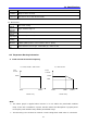
14.1 Technical data
z Input & output ratings
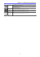
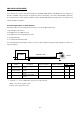
Model: CI – xxx – C2 – 1P 001 002 003 004
[HP] 0.5 1 2 3
Max motor
capacity
1
[kW] 0.4 0.75 1.5 2.2
Capacity [kVA]
2
0.95 1.9 3.0 4.5
FLA [A] 2.5 5 8 12
Frequency 0 ~ 400 [Hz]
3
Output
ratings
Voltage Three Phase 200 ~ 230V
4
Voltage
Single Phase 200 ~ 230V (±10%)
Frequency
50 ~ 60 [Hz] (±5%)
Input
ratings
Current 5.5 9.2 16 21.6
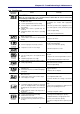
z Control
Control mode V/F control, Sensorless vector control
Frequency setting resolution
Digital: 0.01Hz
Analog: 0.06Hz (Max. frequency: 60Hz)
Accuracy of Frequency
command
Digital: 0.01% of Max. output frequency
Analog: 0.1% of Max. output frequency
V/F Ratio Linear, Squared Pattern, User V/F
Overload capacity Software: 150% for 60 s
Torque boost Auto/Manual torque boost
z Operation
Operation mode Keypad/ Terminal/ Communication option selectable
Frequency setting
Analog: 0 ~ 10[V], 0 ~ 20[mA], Keypad Potentiometer
Digital : Keypad
Operation features PID control, Up-Down operation, 3-wire operation
Input Multi-function terminal
NPN/ PNP selectable
Function: (refer to page 3-5)
Multi-function open
collector terminal
Operating status
Multi-function relay
terminal
Fault output (N.O., N.C.)
Function: (Refer to page 11-6)
Output
Analog output 0 ~ 10 Vdc: Frequency, Current, Voltage, DC link voltage selectable
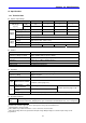
z Protective functions
Inverter
Trip
Over-voltage, Under-voltage, Over-current, Ground fault current detection, Over-temperature
of inverter and motor, Output phase open, Overload, Communication error, Loss of frequency
1
Indicates the maximum applicable motor capacity when using a 4-pole Standard motor.
2
Rated capacity is based on 220V.
3
Max settable freq is 300Hz when H30 is set to 3 “Sensorless Vector Control”.
4
Max output voltage will not be greater than the input voltage. Output voltage less than the input voltage can be
programmed.
122