ENG OWNER'S MANUAL LG CLOUD V SERIES BOX Please read the safety information carefully before using the product. LG Cloud V Series Box Model List CBV42 www.lg.
Table of Contents English ENG 3 ASSEMBLING AND PREPARING 3 Unpacking 4 Parts and Buttons 5 Product Installation 5 - Using in Horizontal Position 5 - Using in Vertical Position 5 - Mounting on the Back of the Monitor 6 CONNECTING LAN/ PERIPHERALS 6 - LAN Connection 6 - DVI Connection 7 - Extended Monitor Connection 7 - Peripheral device connection 9 TROUBLESHOOTING 10 SPECIFICATIONS 10 Power Indicator 11 USING CLOUD SOLUTION
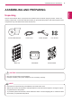
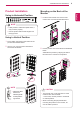
ASSEMBLING AND PREPARING 3 ASSEMBLING AND PREPARING ENG English Unpacking Please check whether all the components are included in the box before using the product. If there are missing components, contact the retail store where you purchased the product. Note that the product and components may look different from those shown here. Owner's Manual/Card Main Unit Power Cord AC/DC Adapter Stand Base Four Screws Mount Bracket CAUTION Only use an approved LG power adapter.
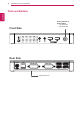
ASSEMBLING AND PREPARING Parts and Buttons English ENG Power Indicator & Power Button yyOn: Power On yyOff: Power Off Front Side DC-IN LAN DVI-D OUT DVI-I OUT Rear Side DC-IN LAN DVI-D OUT 5V 0.1A 5V 0.
ASSEMBLING AND PREPARING Product Installation Mounting on the Back of the Monitor 1 Fix the mount bracket on the back of the monitor with 4 screws as illustrated below. NOTE DC-IN LAN DVI-D OUT DVI-I OUT If this product is used with upside down, it yy 5V 0.1A may not work properly. Use the product with the Kensington lock yy facing upward. Using in Vertical Position 1 Firmly attach the stand on the bottom of the product as illustrated below.
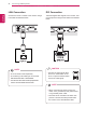
Connecting LAN/Peripherals CONNECTING LAN/PERIPHERALS English ENG LAN Connection DVI Connection Connect the router or switch to the monitor using a LAN cable as illustrated below. Transmits digital video signals to the monitor. Connect the product using the DVI cable as illustrated below. NOTE The LAN cable is sold separately. yy The following LAN cable type can be used: yy Standard: IEEE 802.3 ETHERNET yyConnect the LAN cable and the peripheral devices to use the CITRIX cloud monitor.
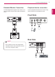
Connecting LAN/Peripherals Peripheral device connection Transmits digital video signals to the monitor. Connect the product using the DVI cable as illustrated below. Connect peripheral devices to the monitor using USB, microphone and headphone ports. Front Side NOTE If the main/sub screen was changed after yy extended monitor was connected, the main/ sub can be changed in Setup.
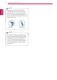
Connecting LAN/Peripherals NOTE English ENG Peripheral devices are sold separately. yy The USB ports can be used to connect the yy keyboard, mouse, and other USB devices. For an angle plug earphone/microphone, it is yy difficult connect it with a peripheral device, so use a straight type. Angle Type Straight Type NOTE yyThe cloud server settings may affect the performance of the headphones, earphones or speakers depending on the connected cloud server.
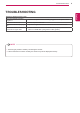
TROUBLESHOOTING 9 TROUBLESHOOTING Is the power adapter of the Box plugged in ? yy Check if the power cord is correctly plugged in to the power outlet. Is the power indicator on? yy Check the power indicator. Is the power indicator displaying as red? yy Adjust the brightness and the contrast of the connected monitor. Are the BOX and the monitor connected with the signal cable? yy Check whether the monitor and the Box are properly connected to DVI cable or D-SUB cable (using DVI to D-Sub gender).
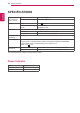
SPECIFICATIONS SPECIFICATIONS English ENG Supported Display Resolution (DVI-I, DVI-D) Power Dimension Weight (Without Packaging) AC/DC adapter Environmental Conditions Maximum Resolution 1920 x 1200 @ 60 Hz Recommended Resolution 1920 x 1200 @ 60 Hz Voltage 19 V 1.2 A Power consumption (Typ.) Cloud Mode 6 W (Cloud) Off Mode ≤ 0.5 W Dimensions (Width x Height x Depth) With stand 70.3 mm x 189.3 mm x 143.6 mm Without Stand 185 mm x 30.5 mm x 143.6 mm 0.
Using CLOUD Solution 11 USING CLOUD SOLUTION ENG English NOTE Menus and functions in CLOUD mode may yy be slightly different depending on the firmware version.You can download the user manual for each version from the Teradici homepage: http://www.teradici.com To check the firmware version, see page yy <47>. Connect Screen The Connect screen is shown during start-up, except when the portal has been configured for a managed start-up or auto-reconnect.
Using CLOUD Solution English ENG If you select the Connect button, the connection session is started. When the connection is pending, the "Discovering hosts, please wait…" message is displayed on the OSD local GUI.When the connection is established, the OSD local GUI will disappear and be replaced by the session image. OSD Options Menu Selecting the Options menu will produce a list of selections.
Using CLOUD Solution NOTE The network parameters can also be conyy figured using the Webpage Administration Interface. yy Gateway The Gateway field contains the gateway IP address of the device. If DHCP is disabled, this field is required. If DHCP is enabled, this field cannot be edited. yy Primary DNS Server The Primary DNS Server field contains the primary DNS IP address of the device. This field is optional. If DHCP is enabled, this field cannot be edited.
Using CLOUD Solution English ENG Tab The IPv6 tab is used when the portal is connected to the network configured with the IP v6. yy Secondary DNS Server The Secondary DNS Server field contains the secondary DNS IP address of the device. This field is optional. If DHCPv6 is enabled, this field cannot beedited. yy Domain Name The Domain Name field contains the domain name used, e.g. "domain local". This field is optional. It specifies on which domain the host or portal operates.
Using CLOUD Solution NOTE The portal label parameters can also be conyy figured using the Webpage Administration Interface. Discovery Tab The Discovery tab allows the administrator to easily find a portal in the PCoIP system. NOTE The Discovery parameters can also be conyy figured using the Webpage Administration Interface.
Using CLOUD Solution English ENG Session Tab The Session tab allows the administrator to set the method to connect the device to a peer device. See below for information how to set for each option. NOTE The Session parameters can also be conyy figured using the Webpage Administration Interface. yy Connection Type The Connection Type field allows the user to select the device to be connected with the portal.
Using CLOUD Solution 17 yy Enable Auto-Reconnect If this option is selected, reconnection is attempted automatically when a session is disconnected or the user is logged off. NOTE This setting is provided only for the client. yy yy Enable Peer Loss Overlay The "Connection Lost" message is displayed.The display is the same as in the VDI environ-ment. The default is Disable. NOTE yyThis setting is provided only for the client.
Using CLOUD Solution English ENG yy View Connection Server In the Session tab, you can select to enable the user client to access the VMware View ConnectionServer. To do this, select View Connection Server for Connection Type. yy Enable Auto-Reconnect If this option is selected, reconnection is attempted automatically when a session is disconnected or the user is logged off.
Using CLOUD Solution 19 NOTE This setting is provided only when a smart yy card is used. yy Desktop Name to Select Enter the name of the pool/desktop which the user client uses upon starting a session. yy Port For the default setting, leave the port field empty. When the VMware View Connection Server uses the SSL authentication, enter 443 in the Port field.
Using CLOUD Solution English ENG yy View Connection Server with Auto-Logon In the Session tab, you can select to enable the user client to automatically access the VMware View Connection Server.To do this, select View Connection Server with Auto-Logon for Connection Type.
Using CLOUD Solution NOTE This setting is provided only when a smart yy card is used. yy View Connection Server + Kiosk Select View Connection Server + Kiosk to use the kiosk mode. You can configure the View Connection Server + Kiosk mode using the Webpage Administration Interface. NOTE You cannot use the kiosk mode by connectyy ing to the host PC.
Using CLOUD Solution English ENG yy Enable Preparing Desktop Overlay If this option is selected, the "Preparing Desktop" message is displayed on the screen when the user is logged in. yy Disconnect Message Filter This option determines the type of message to display when a session is disconnected. - Show All: Shows all the error messages. - Show Error and Warning Only: Shows the error and warning messages only.
Using CLOUD Solution 23 yy Remember Username If this option is selected, the username which is previously used to access the VMware View Connection Server is automatically entered in the username field. yy Use OSD logo for View banner If this option is enabled, you can change the OSD logo of PCoIP during the login.
Using CLOUD Solution English ENG Language Tab The Language tab allows the administrator to set the OSD language. NOTE The Language parameters can also be conyy figured using the Webpage Administration Interface. yy Enable Peer Loss Overlay If this option is selected, the "Network Connection Lost" message is displayed on the screen when it is confirmed that the network is disconnected.
Using CLOUD Solution NOTE The OSD parameters can also be configured yy using the Webpage Administration Interface. yy Screen-Saver Timeout The Screen-Saver Timeout field allows the administrator to set a time limit for the screen saver. The time limit is defined in seconds. The maximum time is 9999 seconds. If it is set to 0 seconds, the screen saver will be turned off. Display Tab The Display tab allows the user to configure the EDID function of the monitor.
Using CLOUD Solution English ENG Reset Tab The Reset tab allows the administrator to reset all configurable parameters stored in Flash. NOTE The Reset function can also be accessed yy through the Webpage Administration Interface. Diagnostics Window In the Diagnostics window, the administrator can access the window tab to diagnose the portal. The Diagnostics window has the following tabs: yy Event Log yy Session Statistics yy PCoIP Processor yy Ping Each tab has the Close button to close the window.
Using CLOUD Solution PCoIP Processor Tab The PCoIP Processor tab allows the administrator to view the portal PCoIP processor's uptime since its last booting. NOTE The session statistics (regardless of the yy quantity) can also be viewed using the Webpage Administration Interface. NOTE The PCoIP Processor Uptime can also be yy viewed using the Webpage Administration Interface.
Using CLOUD Solution English ENG Ping Tab The Ping tab allows the administrator to perform a ping test to the device and check if it can reach the overall IP network. This is useful to check whether the device can reach the host. NOTE The Ping tab has no corresponding menu in yy to the Webpage Administration Interface of Section 1. yy Ping Settings yy Destination The IP address or FQDN to perform the ping test.
Using CLOUD Solution yy VMware View Tab The VMware View tab allows user to specify the client behavior for when a user cannot check the secure connection to a server. yy Reject the unverifiable connection (Secure) Connection can be established only when the certificate is verified and otherwise it cannot. yy Warn if the connection may be insecure (Default) The authentication status is checked and a warning message is displayed, if required. However, there is no connection limit.
Using CLOUD Solution English ENG Keyboard Tab The Keyboard tab allows the user to modify the OSD and RDP session's keyboard repeat setting. NOTE The OSD keyboard setting does not affect yy the keyboard settings when a PColP session is active unless the Local Keyboard Host Driver function is being used (see PColP Host Software User Guide for more information). The Keyboard tab has no corresponding yy menu in the Webpage Administration Interface of Section 1.
Using CLOUD Solution yy Touch Screen Tab The Touch Screen tab allows the user to specify the touch sensitivity and alignment when the monitor supports the touch screen function. NOTE yyIt is applicable when the VMware View Connection Server version is 4.5 or later. yy Enable Configuration When this option is selected, you can set the display position and alignment.
Declaration of Conformity Trade Name: LG Model : CBV42L Responsible Party: LG Electronics Inc. Address : 1000 Sylvan Ave. Englewood Cliffs NJ 07632 U.S.A TEL: 201-266-2534 *above information is only for USA FCC Regulatory This device meets the EMC requirements for home appliances (Class B) and is intended for home use. This device can be used in all regions. Read the owner's manual (CD) carefully and keep it at hand. The product label contains necessary information for after-service. Model Serial No.