
Instructions / Assembly


25INSTALLATION
ENGLISH
Three-Wire Power Cord
• A 3-wire connection is NOT permitted
on new construction after January 1,
1996.
• A UL-listed strain relief is required.
• Use a 30-amp, 240-volt, 3-wire,
UL-listed power cord with #10 AWG-
minimum copper conductor and closed
loop or forked terminals with upturned
ends.
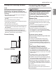
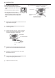
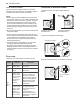
1
Remove the terminal block access cover on the
upper back of the dryer.
2
Install a UL-listed strain relief into the power
cord through-hole.
3
Thread a 30-amp, 240-volt, 3-wire, UL-listed
power cord with #10 AWG-minimum copper
conductor through the strain relief.
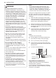
Terminal Block
UL-Listed Strain Relief
UL-Listed 3-Wire Power
Cord
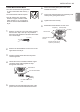
4
Attach the two hot leads (black and red) of the
power cord to the outer terminal block screws.
5
Attach the neutral (white) wire to the center
terminal block screw.
6
Connect the external ground (if required by local
codes) to the green ground screw.
7
Tighten all screws securely.
8
Reinstall the terminal block access cover.
Hot (Black)
Ground Screw
White Wire from Dryer
harness
External Ground Wire (If
required by local codes)
Hot (Red)
Neutral (White)
Three-Wire Direct Wire
• A 3-wire connection is NOT permitted
on new construction after January 1,
1996.
• A UL-listed strain relief is required.
• Use UL-listed 3-wire, #10 AWG-
minimum copper conductor cable.
Allow at least 5 ft. (1.5 m) length to
allow for removal and installation of
dryer.
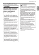
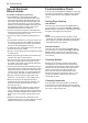
1
Remove 3.5-inch (8.9 cm) of the outer covering
from the wire. Strip 1 inch (2.5 cm) insulation
from each wire. Bend the ends of the three wires
into a hook shape.
1" (2.5 cm)
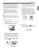
2
Remove the terminal block access cover on the
upper back of the dryer.
3
Install a UL-listed strain relief into the power
cord through-hole.
4
Thread the 3-wire, #10 AWG-minimum copper
conductor power cable prepared in step 1
through the strain relief.
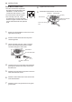
Terminal Block
UL-Listed Strain Relief
UL-Listed 3-Wire Power
Cord
5
Attach the two hot leads (black and red) of the
power cord to the outer terminal block screws.
6
Attach the neutral (white) wire to the center
terminal block screw.
7
Connect the external ground (if required by local
codes) to the green ground screw.
8
Tighten all screws securely.
9
Reinstall the terminal block access cover.
Hot (Black)
Ground Screw
White Wire from Dryer
harness
External Ground Wire (If
required by local codes)
Hot (Red)
Neutral (White)