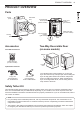
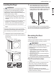
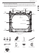
PRODUCT OVERVIEW 9 PRODUCT OVERVIEW Parts Control panel Reversible door Lint filter Leveling feet Accessories Terminal block access panel (electric models) Gas connection location (gas models) Power cord location (gas models) Water inlet valve (on some models) Exhaust duct outlet Two-Way Reversible Door (on some models) Included Accessories Release Safety Tether Kit (on some models) Hamper door Optional Accessories Swing door Drying rack (sold separately) No.
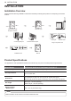
10 INSTALLATION INSTALLATION Installation Overview Please read the following installation instructions first after purchasing this product or transporting it to another location. Check and choose the proper location Level the dryer Connect electric dryers Connect gas dryers Installation test Vent the dryer Gas dryer Electric dryer Plug in the power cord Test run Product Specifications The appearance and specifications listed in this manual may vary due to constant product improvements.
INSTALLATION 11 Installation Location Requirements WARNING Read all installation instructions completely before installing and operating the dryer! It is important that you review this entire manual before installing and using the dryer. Detailed instructions concerning electrical connections, gas connections, and exhaust requirements are provided on the following pages. The installation requires: •• A location that allows for proper exhaust installation. A gas dryer must be exhausted to the outdoors.
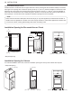
12 INSTALLATION Closet Ventilation Requirements Closets with doors must have both an upper and lower vent to prevent heat and moisture buildup in the closet. One upper vent opening with a minimum opening of 48 sq. in. (310 cm2) must be installed no lower than 6 feet above the floor. One lower vent opening with a minimum opening of 24 sq. in. (155 cm2) must be installed no more than one foot above the floor. Install vent grills in the door or cut down the door at the top and bottom to form openings.
INSTALLATION 13 Leveling the Dryer 2 WARNING To reduce the risk of injury to persons, adhere to all industry recommended safety procedures including the use of long-sleeved gloves and safety glasses. Failure to follow this warning may result in serious injury or death. Use an adjustable wrench to turn the leveling feet. Unscrew the legs to raise the dryer or screw in the legs to lower it. Raise or lower with the leveling feet until the dryer is level from side to side and front to back.
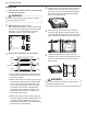
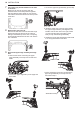
14 INSTALLATION Swing door 1 Open the door from the side so that the hinge screws are accessible. 4 WARNING Be sure to support the weight of the door before removing the hinge screws. 2 Remove the four hinge screws. While supporting the door, remove the four hinge screws, two from each hinge. Set the door aside face down on a protected surface to prevent damage to the door or the work surface.
INSTALLATION 15 7 Reinstall the door. While supporting the door, install the four hinge screws removed in step 2. Test the swing of the door to make sure the hinges and latch are properly aligned and that the door opens, closes and latches properly. 2 Remove the door from cabinet. a. W hile supporting the door, remove the four hinge screws. Two large screws Two small screws b. L ift the door slightly to disengage the hinge support and remove the door from the cabinet.
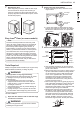
16 INSTALLATION Twelve screws CAUTION Do NOT remove any of the eight screws on the face of the cabinet (marked below). Doing so could result in damage to the dryer and the need for a service call to repair the dryer. Hole plug e. Remove the three screws on the hinge at the bottom left. Remove the hinge and reinstall it on the right side. The top screw will occupy the hole where you removed the screw behind the hinge bracket in step d. 5 Side Interlock button Switch the door strike and the blank cover.
INSTALLATION 17 6 Reverse the components inside the door. You will now be removing and reversing various components inside the door. See below for a detailed diagram and identification of the inner structure and parts of the door. (The diagram shows the “before view” of the door, with the default set-up for a right side hinge swing. After following these instructions, the door should be a mirror image of the illustration.
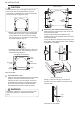
18 INSTALLATION 7 Lift out the gray interlock button in the side of the door. Make sure to remove the spring with the interlock button and to keep the two together. Set the interlock button aside. Do not confuse this with the interlock buttons from the top of the outer door. 8 Remove the side lock rod. Remove the side lock rod from the lower hinge bracket by lifting the top end of the rod and sliding it toward the top of the door. The spring should remain attached to the lock rod.
INSTALLATION 19 10 Reverse the lower hinge bracket and hinge assembly. a. Remove one screw from the lower hinge bracket (on the right) and lift it out. Remove two screws from the lower hinge assembly (on the left) and lift it out. 11 Install the side lock rod. a. F lip the side lock rod over and insert the lower end into the left hinge bracket. b. L ower the rod into the guides on the door while compressing the spring inside the recess.
20 INSTALLATION 12 Reinstall the side interlock button. Install the side interlock button on the opposite side from which it was removed. NOTE Make sure the spring is on the interlock button and is centered in the compartment. 13 Reinstall the door cover. a. Clean the glass on the door and door cover, if necessary. b. Make sure the three gray interlock buttons are properly installed and that the top and side lock rods intersect properly. c.
INSTALLATION 21 Installing the Side Vent Kit 3 WARNING •• Use a heavy metal vent. •• Do not use plastic or thin foil ducts. •• Clean old ducts before installing this dryer. •• To reduce the risk of injury to persons, adhere to all industry recommended safety procedures including the use of long-sleeved gloves and safety glasses. •• Failure to follow all of the safety warnings in this manual could result in property damage, injury to persons, or death. Preassemble a 4-inch (10.
22 INSTALLATION Venting the Dryer WARNING To reduce the risk of fire or explosion, electric shock, property damage, injury to persons or death when using this appliance, follow basic safety precautions, including the following: •• Do not crush or collapse ductwork. Failure to follow these instructions may result in fire or death. •• Do not allow ductwork to rest on or contact sharp objects. Failure to follow these instructions may result in fire or death.
INSTALLATION 23 Routing And Connecting Ductwork NOTE Follow the guidelines below to maximize drying performance and reduce lint buildup and condensation in the ductwork. Ductwork and fittings are NOT included and must be purchased separately. •• Use 4-inch (10.2 cm) diameter rigid, semi-rigid or flexible metal ductwork. •• The exhaust duct run should be as short as possible. •• Use as few elbow joints as possible. •• The male end of each section of exhaust duct must point away from the dryer.
24 INSTALLATION Connecting Gas Dryers WARNING To reduce the risk of fire or explosion, electric shock, property damage, injury to persons, or death when using this appliance, follow basic safety precautions. Gas Supply Requirements •• Use only a new AGA- or CSA-certified gas supply line (in compliance with the Standard for Connectors for Gas Appliances, ANSI Z21.24 • CSA 6.10) with flexible stainless steel connectors. •• Securely tighten all gas connections.
INSTALLATION 25 Connecting the Gas Supply •• Installation and service must be performed by a qualified installer, service agency, or the gas supplier. Failure to do so may result in fire, explosion, or death. •• Use only a new stainless steel flexible connector and a new AGA-certified connector. Failure to do so may result in fire, explosion, or death. •• A gas shutoff valve must be installed within 6 ft. (1.8 m) of the dryer. Failure to do so may result in fire, explosion, or death.
26 INSTALLATION Connecting Electric Dryers Electrical Requirements for Electric Models Only WARNING To help prevent fire, electric shock, serious injury, or death, the wiring and grounding must conform to the latest edition of the National Electrical Code, ANSI/NFPA 70 and all applicable local regulations. Please contact a qualified electrician to check your home’s wiring and fuses to ensure that your home has adequate electrical power to operate the dryer.
INSTALLATION 27 WARNING Connect the power cord to the terminal block. Connect each wire in the power cord to the terminal block screw with the matching colored wire. The terminal block wire colors are indicated in the manual. Failure to follow these instructions may result in a short or overload. Grounding through the neutral conductor is prohibited for: (1) new branch-circuit installations, (2) areas where local codes prohibit grounding through the neutral conductor.
28 INSTALLATION Four-Wire Direct Wire 7 Attach the white neutral wire to the center screw of the terminal block. •• Use UL-listed 4-wire #10 AWGminimum copper conductor cable. Allow at least 5 ft. (1.5 m) of wire to allow for removal and reinstallation of the dryer. 8 Attach the power cord ground wire to the green ground screw. 9 Tighten all screws securely. 1 10 •• A UL-listed strain relief is required. Remove 5 inches (12.7 cm) of the outer covering from the wire. Remove 5 inches (12.
INSTALLATION 29 5 WARNING Connect the power cord to the terminal block. Connect each wire in the power cord to the terminal block screw with the matching colored wire. The terminal block wire colors are indicated in the manual. Failure to follow these instructions may result in a short or overload. Grounding through the neutral conductor is prohibited for: (1) new branch-circuit installations, (2) areas where local codes prohibit grounding through the neutral conductor.
30 INSTALLATION Three-Wire Direct Wire 9 Reinstall the terminal block access cover. Hot (Black) •• A 3-wire connection is NOT permitted on new construction after January 1, 1996. •• A UL-listed strain relief is required. •• Use UL-listed 3-wire, #10 AWG-minimum copper conductor cable. Allow at least 5 ft. (1.5 m) length to allow for removal and installation of dryer. 1 Remove 3½-inch (8.9 cm) of the outer covering from the wire. Strip 1 inch (2.5 cm) insulation from each wire.
INSTALLATION 31 Installation Test (Duct Check) 4 Once you have completed the installation of the dryer, use this test to make sure the condition of the exhaust system is adequate for proper operation of the dryer. This test should be performed to alert you to any serious problems in the exhaust system of your home. •• This dryer features Flow Sense™, an innovative sensing system that automatically detects blockages and restrictions in dryer ductwork.