0 INSTALLATION INSTALLATION Installation Overview Please read the following installation instructions first after purchasing this product or transporting it to another location. Check and choose the proper location Level the dryer Connect gas dryers Connect electric dryers Installation test Vent the dryer Gas dryer Electric dryer Plug in the power cord Test run Product Specifications The appearance and specifications listed in this manual may vary due to constant product improvements.
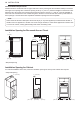
INSTALLATION 11 Installation Location Requirements WARNING Read all installation instructions completely before installing and operating the dryer! It is important that you review this entire manual before installing and using the dryer. Detailed instructions concerning electrical connections, gas connections, and exhaust requirements are provided on the following pages. The installation requires: •• A location that allows for proper exhaust installation. A gas dryer must be exhausted to the outdoors.
12 INSTALLATION Closet Ventilation Requirements Closets with doors must have both an upper and lower vent to prevent heat and moisture buildup in the closet. One upper vent opening with a minimum opening of 48 sq. in. (310 cm2) must be installed no lower than 6 feet above the floor. One lower vent opening with a minimum opening of 24 sq. in. (155 cm2) must be installed no more than one foot above the floor. Install vent grills in the door or cut down the door at the top and bottom to form openings.
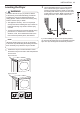
INSTALLATION 13 Leveling the Dryer 2 WARNING To reduce the risk of injury to persons, adhere to all industry recommended safety procedures including the use of long-sleeved gloves and safety glasses. Failure to follow this warning may result in serious injury or death. Use an adjustable wrench to turn the leveling feet. Unscrew the legs to raise the dryer or screw in the legs to lower it. Raise or lower with the leveling feet until the dryer is level from side to side and front to back.
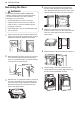
14 INSTALLATION Reversing the Door 4 WARNING THE DRYER DOOR IS VERY LARGE AND HEAVY. Failure to follow the instructions below can result in damage to the dryer, property damage or injury to persons. Remove the 4 screws securing the hinges to the door frame. Remove the two plastic cover caps. Reinstall the hinges and cover caps on the opposite sides from which they were removed.
INSTALLATION 15 Installing the Side Vent Kit 3 WARNING •• Use a heavy metal vent. •• Do not use plastic or thin foil ducts. •• Clean old ducts before installing this dryer. •• To reduce the risk of injury to persons, adhere to all industry recommended safety procedures including the use of long-sleeved gloves and safety glasses. •• Failure to follow all of the safety warnings in this manual could result in property damage, injury to persons, or death. Preassemble a 4-inch (10.
16 INSTALLATION Venting the Dryer WARNING To reduce the risk of fire or explosion, electric shock, property damage, injury to persons or death when using this appliance, follow basic safety precautions, including the following: •• Do not crush or collapse ductwork. Failure to follow these instructions may result in fire or death. •• Do not allow ductwork to rest on or contact sharp objects. Failure to follow these instructions may result in fire or death.
INSTALLATION 17 Routing And Connecting Ductwork NOTE Follow the guidelines below to maximize drying performance and reduce lint buildup and condensation in the ductwork. Ductwork and fittings are NOT included and must be purchased separately. •• Use 4-inch (10.2 cm) diameter rigid, semi-rigid or flexible metal ductwork. •• The exhaust duct run should be as short as possible. •• Use as few elbow joints as possible. •• The male end of each section of exhaust duct must point away from the dryer.
18 INSTALLATION Connecting Gas Dryers WARNING To reduce the risk of fire or explosion, electric shock, property damage, injury to persons, or death when using this appliance, follow basic safety precautions. Gas Supply Requirements •• Use only a new AGA- or CSA-certified gas supply line (in compliance with the Standard for Connectors for Gas Appliances, ANSI Z21.24 • CSA 6.10) with flexible stainless steel connectors. •• Securely tighten all gas connections.
INSTALLATION 19 Connecting the Gas Supply •• Installation and service must be performed by a qualified installer, service agency, or the gas supplier. Failure to do so may result in fire, explosion, or death. •• Use only a new stainless steel flexible connector and a new AGA-certified connector. Failure to do so may result in fire, explosion, or death. •• A gas shutoff valve must be installed within 6 ft. (1.8 m) of the dryer. Failure to do so may result in fire, explosion, or death.
20 INSTALLATION Connecting Electric Dryers Electrical Requirements for Electric Models Only WARNING To help prevent fire, electric shock, serious injury, or death, the wiring and grounding must conform to the latest edition of the National Electrical Code, ANSI/NFPA 70 and all applicable local regulations. Please contact a qualified electrician to check your home’s wiring and fuses to ensure that your home has adequate electrical power to operate the dryer.
INSTALLATION 21 WARNING Connect the power cord to the terminal block. Connect each wire in the power cord to the terminal block screw with the matching colored wire. The terminal block wire colors are indicated in the manual. Failure to follow these instructions may result in a short or overload. Grounding through the neutral conductor is prohibited for: (1) new branch-circuit installations, (2) areas where local codes prohibit grounding through the neutral conductor.
22 INSTALLATION Four-Wire Direct Wire 7 Attach the white neutral wire to the center screw of the terminal block. •• Use UL-listed 4-wire #10 AWGminimum copper conductor cable. Allow at least 5 ft. (1.5 m) of wire to allow for removal and reinstallation of the dryer. 8 Attach the power cord ground wire to the green ground screw. 9 Tighten all screws securely. 1 10 •• A UL-listed strain relief is required. Remove 5 inches (12.7 cm) of the outer covering from the wire. Remove 5 inches (12.
INSTALLATION 23 5 WARNING Connect the power cord to the terminal block. Connect each wire in the power cord to the terminal block screw with the matching colored wire. The terminal block wire colors are indicated in the manual. Failure to follow these instructions may result in a short or overload. Grounding through the neutral conductor is prohibited for: (1) new branch-circuit installations, (2) areas where local codes prohibit grounding through the neutral conductor.
24 INSTALLATION Three-Wire Direct Wire 9 Reinstall the terminal block access cover. Hot (Black) •• A 3-wire connection is NOT permitted on new construction after January 1, 1996. •• A UL-listed strain relief is required. •• Use UL-listed 3-wire, #10 AWG-minimum copper conductor cable. Allow at least 5 ft. (1.5 m) length to allow for removal and installation of dryer. 1 Remove 3½-inch (8.9 cm) of the outer covering from the wire. Strip 1 inch (2.5 cm) insulation from each wire.
INSTALLATION 25 Installation Test (Duct Check) 4 Once you have completed the installation of the dryer, use this test to make sure the condition of the exhaust system is adequate for proper operation of the dryer. This test should be performed to alert you to any serious problems in the exhaust system of your home. •• This dryer features Flow Sense™, an innovative sensing system that automatically detects blockages and restrictions in dryer ductwork.