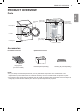
PRODUCT OVERVIEW 9 PRODUCT OVERVIEW Reversible door ENGLISH Parts Power Cord (gas models) Terminal Block Access Panel (electric models) Control panel Lint filter Leveling feet Gas connection (gas models) Exhaust Duct Outlet Accessories Included Accessories Drying Rack (on some models) Optional Accessories Pedestal (sold separately) Stacking kit (sold separately) NOTE • For your safety and extended product life, use only authorized components.
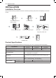
10 INSTALLATION INSTALLATION Installation Overview Please read the following installation instructions first after purchasing this product or transporting it to another location. Check and choose the proper location Level the dryer Connect the Gas dryer Vent the dryer Connect the Electric dryer Gas dryer Electric dryer Plug in the power cord Installation test Test run Product Specifications The appearance and specifications listed in this manual may vary due to constant product improvements.
INSTALLATION 11 Installation Location Requirements WARNING The installation requires: • A location that allows for proper exhaust installation. A gas dryer must be exhausted to the outdoors. See Venting the Dryer. • A grounded electrical outlet located within 2 ft. (61 cm) of either side of the dryer. See Connecting Electric Dryers. • A sturdy floor to support the total dryer weight of 200 lb (90.7 kg). The combined weight of a companion appliance should also be considered.
12 INSTALLATION Clearances 14" max.* (356 mm) 14" max.* (356 mm) 18" min.* (457 mm) 18" min.* (457 mm) 1"* 30" (25 mm) (761mm) 1"* 30" (25 mm) (761mm) 5"** (127 mm) 5"** (127 mm) 3" * (76 mm) 48 in. 2* (310 cm 2 ) 0" (0 mm) 39" (991 mm) 24 in. 2* (155 cm 2) 1" (25 mm) 3" * (76 mm) Closet Door Vent Requirements 1" (25 mm) 27" (686 mm) 27" (686 mm) 1" (25 mm) 1" (25 mm) Installation Spacing for Recessed Area or Closet Installation The following clearances are recommended for this dryer.
INSTALLATION 13 Installation Spacing for Recessed Area or Closet, with Stacked Washer and Dryer ENGLISH 48 in. 2* 2 6" * (152 mm) 3" * (76 mm) (310 cm ) 77 ½" (1968 mm) 24 in. 2* (155 cm 2) 3" * (76 mm) 1"* (25 mm) 5 ½" ** (140 mm) 1" (25 mm) 27" (686 mm) 1" (25 mm) * Required spacing ** For side or bottom venting, 2-inch (5.1 cm) of spacing is allowed. Installation Spacing for Cabinet For cabinet installation with a door, minimum ventilation openings in the top of the cabinet are required.
14 INSTALLATION Leveling the Dryer 2 WARNING To reduce the risk of serious injury or death, follow basic precautions, including the following: • Use long-sleeved gloves and safety glasses. • The appliance is heavy. Two or more people are required when installing the dryer. NOTE • Adjust the leveling feet only as far as necessary to level the dryer. Extending the leveling feet more than necessary may cause the dryer to vibrate.
INSTALLATION 15 Reversing the Door 2 While supporting the door, remove the 2 screws on the door hinge. Remove the door. 3 Turn the door upside down and line up the holes in the hinge with the holes on the opposite side of the cabinet. Reinstall the door with the screws removed in step 2.
16 INSTALLATION Installing the Side Vent Kit 3 WARNING To reduce the risk of serious injury, death or property damage, follow basic precautions, including the following: • Use long-sleeved gloves and safety glasses. • Use a heavy metal vent. Preassemble a 4-inch (10.2 cm) elbow to the next 4-inch (10.2 cm) duct section, and secure all joints with duct tape. Be sure that the male end of the elbow faces AWAY from the dryer.
INSTALLATION 17 Stacking the Dryer Stacking Kit Installation 1 Make sure the surface of the washer is clean and dry. Remove paper backing from the tape on one of the stacking kit side brackets. 2 Fit the side bracket to the side of the washer top as shown in the below illustration. Firmly press the adhesive area of the bracket to the washer surface. Secure the side bracket to the washer with a screw on the back side of the bracket. Repeat steps 1 and 2 to attach the other side bracket.
18 INSTALLATION Venting the Dryer WARNING To reduce the risk of fire or explosion, electric shock, property damage, injury to persons or death when using this appliance, follow basic safety precautions, including the following: WARNING • Ductwork is not provided with the dryer. You should obtain the necessary ductwork locally. The vent hood should have hinged dampers to prevent backdraft when the dryer is not in use. • The total length of flexible metal duct must not exceed 8 ft. (2.4 m).
INSTALLATION 19 Routing and Connecting Ductwork • Use 4-inch (10.2 cm) diameter rigid, semi-rigid or flexible metal ductwork. • The exhaust duct run should be as short as possible. • Use as few elbow joints as possible. • The male end of each section of exhaust duct must point away from the dryer. • Use duct tape on all duct joints. • Insulate ductwork that runs through unheated areas in order to reduce condensation and lint buildup on duct surfaces.
20 INSTALLATION WARNING Gas Supply Requirements (continued) • Supply line requirements: Your laundry room must have a rigid gas supply line to your dryer. In the United States, an individual manual shutoff valve MUST be installed within at least 6 ft. (1.8 m) of the dryer, in accordance with the National Fuel Gas Code ANSI Z223.1 or Canadian gas installation code CSA B149.1. A 1/8-inch NPT pipe plug must be installed. • If using a rigid pipe, the rigid pipe should be 0.5-inch IPS.
INSTALLATION 21 Connecting Electric Dryers To reduce the risk of fire or explosion, electric shock, property damage, injury to persons, or death when using this appliance, follow requirements including the following: Electrical Requirements for Electric Models Only • The wiring and grounding must conform to the latest edition of the National Electrical Code, ANSI/NFPA 70 and all applicable local regulations.
22 INSTALLATION Four-Wire Power Cord • A 4-wire connection is required for all mobile and manufactured home installations, as well as all new construction after January 1, 1996. 8 Tighten all screws securely. 9 Reinstall the terminal block access cover. Hot (Black) • A UL-listed strain relief is required. • Use a 30-amp, 240-volt, 4-wire, UL-listed power cord with #10 AWGminimum copper conductor and closed loop or forked terminals with upturned ends.
Four-Wire Direct Wire • A 4-wire connection is required for all mobile and manufactured home installations, as well as all new construction after January 1, 1996. • A UL-listed strain relief is required. • Use UL-listed 4-wire #10 AWGminimum copper conductor cable. Allow at least 5 ft. (1.5 m) of wire to allow for removal and reinstallation of the dryer. 1 Remove 5-inch (12.7 cm) of the outer covering from the wire. Remove 5-inch of insulation from the ground wire. Cut off approximately 1.5-inch (3.
24 INSTALLATION Three-Wire Power Cord • A 3-wire connection is NOT permitted on new construction after January 1, 1996. • A UL-listed strain relief is required. • Use a 30-amp, 240-volt, 3-wire, UL-listed power cord with #10 AWGminimum copper conductor and closed loop or forked terminals with upturned ends. 1 Remove the terminal block access cover on the upper back of the dryer. 2 Install a UL-listed strain relief into the power cord through-hole.
INSTALLATION 25 6 Attach the neutral (white) wire to the center terminal block screw. • A UL-listed strain relief is required. 7 Connect the external ground (if required by local codes) to the green ground screw. 8 Tighten all screws securely. 9 Reinstall the terminal block access cover. • A 3-wire connection is NOT permitted on new construction after January 1, 1996. • Use UL-listed 3-wire, #10 AWGminimum copper conductor cable. Allow at least 5 ft. (1.
26 INSTALLATION Special Electrical Requirements (For Mobile or Manufactured Homes) • Any installation in a manufactured or mobile home must comply with the Manufactured Home Construction and Safety Standards Title 24 CFR, Part 3280 or Standard CAN/ CSA Z240 MH and local codes and ordinances. If you are uncertain whether your proposed installation will comply with these standards, please contact a service and installation professional for assistance.
INSTALLATION 27 Installation Test (Duct Check) 4 • Your dryer features Flow Sense™, an innovative sensing system that automatically detects blockages and restrictions in dryer ductwork. Keeping ductwork clean of lint buildup and free of restrictions allows clothes to dry faster and reduces energy use. Press the START/PAUSE button. The dryer will start the test, which will last a few minutes. The heat will be turned on and the temperatures in the drum will be measured. Check the display for results.
28 INSTALLATION Check the Duct Condition If the Flow Sense™ LED is turned on, check the exhaust system for restrictions and damage. Repair or replace the exhaust system as needed. NOTE • When the dryer is first installed, this test should be performed to alert you to any existing problems with the exhaust duct in your home.
INSTALLATION 29 Restricted or Blocked Airflow Avoid long runs or runs with multiple elbows or bends. ENGLISH Excess or crushed transition duct Too many elbows or exhaust too long Check for blockages and lint buildup. Lint buildup or blockage Make sure the ductwork is not crushed or restricted.
30 OPERATION OPERATION WARNING • To reduce the risk of fire, electric shock, or injury to persons, read the SAFETY INSTRUCTIONS before operating this appliance. Using the Dryer 1 Clean the Lint Filter 2 Load the Dryer 3 Turn on the Dryer 4 Select a Cycle If the lint filter has not already been cleaned, lift out the filter and remove the lint from the last load. This will help ensure the fastest and most efficient drying performance.
OPERATION 31 Check the Lint Filter Before Every Load Always ensure the lint filter is properly installed before running the dryer. Running the dryer with a loose or missing lint filter will damage the dryer and articles in the dryer. For best results, sort clothes into loads that can be dried with the same drying cycle. Different fabrics have different care requirements, and some fabrics will dry more quickly than others.
32 OPERATION Control Panel Non-Steam Models (DLE3500*, DLG3501*) 7 1 2 6 3 5 4 Steam Models (DLEX3700*, DLGX3701*) 8 7 1 2 3 6 5 4 Steam Models (DLEX3900*, DLGX3901*) 8 7 1 2 3 NOTE • Model numbers can be found on the cabinet inside the door.
OPERATION 33 1 Power Button Press the button to turn the dryer ON. Press again to turn the dryer OFF. 2 Cycle Selector Knob Turn this knob to select the desired cycle. Once the desired cycle has been selected, the standard presets will be shown in the display. On Manual Dry cycles, these settings can be adjusted using the cycle Modifier buttons anytime before starting the cycle. 3 Start/Pause Button Press this button to start the selected cycle.
34 OPERATION 9 13 14 10 15 11 12 9 Flow Sense™ Duct Blockage Sensing System Indicator The Flow Sense™ duct blockage sensing system detects and alerts you to blockages in the ductwork that reduce exhaust flow from the dryer. Maintaining a clean exhaust system improves operating efficiency and helps minimize service calls, saving you money. 10 Custom PGM If you have a special combination of settings that you use frequently, you can save these settings as a Custom Program.
OPERATION 35 Cycle Guide Sensor Dry cycles utilize LG’s unique dual sensor system to detect and compare the moisture level in clothes and in the air and adjust the drying time as needed to ensure superior results. The dryer automatically sets the dryness level and temperature at the recommended setting for each cycle. The estimated time remaining will be shown in the display. NOTE • To protect your garments not every dryness level, temperature, or option is available with every cycle.
36 OPERATION Non-Steam Models (DLE3500*, DLG3501*) = default setting ● = allowable option * = Energy Saver Cycle Fabric Type Dry Level Temp. Time in Min. Wrinkle Care Damp Dry Signal Anti Bacterial SENSOR DRY Normal* Work clothes, corduroys, etc. Normal Heavy Duty Jeans, heavyweight items Normal Bedding Comforters, Pillows, Shirts Normal Towels Denims, towels, heavy cottons Normal Small Load Only normal & cotton/ towels fabric type (Max. 3lb) Normal Perm.
OPERATION 37 Steam Models (DLEX3700*, DLGX3701*) = default setting ● = allowable option * = Energy Saver Fabric Type Dry Level Temp. Time in Min. Wrinkle Care Damp Dry Signal Reduce Static ● ● ● ● ● ● SENSOR DRY Normal Normal* Work clothes, corduroys, etc. Heavy Duty Jeans, heavyweight items Normal Bedding Comforters, pillows, shirts Normal Anti Bacterial Do not use this cycle with delicate fabrics Very Perm.
38 OPERATION Steam Models (DLEX3900*, DLGX3901*) = default setting ● = allowable option * = Energy Saver Cycle Fabric Type Dry Level Temp. Time in Min. Wrinkle Care Damp Dry Signal Reduce Static SENSOR DRY Normal* Work clothes, corduroys, etc. Normal Heavy Duty Jeans, heavyweight items Normal Bedding Comforters, pillows, shirts Normal Small Load Only normal & cotton/ towels fabric type (Max. 3lb) Normal Anti Bacterial Do not use this cycle with delicate fabrics Very Perm.
OPERATION 39 Option Buttons Sensor Dry cycles have preset settings that are selected automatically. Manual Dry cycles have default settings, but you may also customize the settings using the cycle modifier buttons. Press the button for that option to view and select other settings. The dryer features several additional cycle options to customize cycles to meet individual needs.
40 OPERATION Special Functions Some cycle option buttons also activate secondary functions. These special functions are marked with an asterisk (*). Press and hold the option button marked with the special function to activate it. Control Lock Use this option to prevent unwanted use of the dryer or to keep cycle settings from being changed while the dryer is operating. Activating the Control Lock Function Press and hold the Wrinkle Care button for 3 seconds.
OPERATION 41 Using the Steam Fresh™ Cycle Turn on the dryer and turn the cycle selector knob to select the Steam Fresh™ cycle. 2 To add an option function, select Reduce Static, or Wrinkle Care. 3 The display shows the load size (number of items). Change the steam time by pressing the More Time or Less Time buttons to fit the size of the load. 4 Press Start/Pause to start the cycle.
42 OPERATION STEAM STEAM SANITARY™ STEAM FRESH™ STEAM OPTION TIME DRY DEFAULT TIME TEMP. DRY LEVEL 39 minutes 20 minutes FABRIC STATE FABRIC TYPE MAXIMUM AMOUNT Comforter Bedding Single (1 each) Children’s clothing 3 lbs. Comforter Single (1 each) Shirts* 5 each Dry Shirts* 8 lbs. (18 Items.) Dry ● Dry REDUCE STATIC 10 minutes REDUCE STATIC FOLLOWS SELECTED CYCLE ● Wet Varies by selected cycle 8 lbs. (18 Items.
SMART FUNCTIONS 43 SMART FUNCTIONS The LG SmartThinQ application allows you to communicate with the appliance using a smartphone. Before Using LG SmartThinQ • For appliances with the 1 or logo Use a smartphone to check the strength of the wireless router (Wi-Fi network) near the appliance. • If the distance between the appliance and the wireless router is too far, the signal strength becomes weak. It may take a long time to register or installation may fail.
44 SMART FUNCTIONS LG SmartThinQ Application Features • For appliances with the or logo Dryer Cycle Download new and special cycles that are not included in the basic cycles on the appliance. Appliances that have been successfully registered can download a variety of specialty cycles specific to the appliance. Only one cycle can be stored on the appliance at a time. Once cycle download is completed in the appliance, the appliance keeps the downloaded cycle until a new cycle is downloaded.
SMART FUNCTIONS 45 FCC RF Radiation Exposure Statement This equipment should be installed and operated with a minimum distance of 20 cm (7.8 inches) between the antenna and your body. Users must follow the specific operating instructions for satisfying RF exposure compliance. Open Source Software Notice Information To obtain the source code under GPL, LGPL, MPL, and other open source licenses, that is contained in this product, please visit http://opensource.lge.com.
46 SMART FUNCTIONS SmartThinQ Smart Diagnosis™ • For appliances with the or logo Use the Smart Diagnosis feature in the SmartThinQ application for help diagnosing issues with the appliance without the assistance of the LG Customer Information Center. Follow the instructions in the SmartThinQ application to perform a Smart Diagnosis using your smartphone. NOTE • Smart Diagnosis™ cannot be activated unless the appliance can be turned on using the Power button.