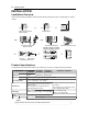
0 INSTALLATION INSTALLATION Installation Overview Please read the following installation instructions first after purchasing this product or transporting it to another location.
INSTALLATION 11 Installation Location Requirements WARNING Read all installation instructions completely before installing and operating your dryer. It is important that you review this entire manual before installing and using your dryer. Detailed instructions concerning electrical connections, gas connections, and exhaust requirements are provided on the following pages.
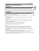
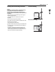
12 INSTALLATION Clearances 14" max.* (356 mm) 14" max.* (356 mm) 18" min.* (457 mm) 18" min.* (457 mm) 1"* (25 mm) 1"* 5"** 30 - 30 (25 mm) 1/8" (127 mm) (761 - 765mm) 30 - 30 5"** 1/8" (127 mm) (761 - 765mm) 3"* (76 mm) in.2* 2 48 (310 cm ) 0" (0 mm) 39" (990 mm) 24 in.
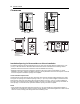
INSTALLATION 13 Installation Spacing for Recessed Area or Closet, with Stacked Washer and Dryer 48 in.2* (310 cm2 ) 6"* (152 mm) 3"* (76 mm) 77 ½" (1968 mm) 24 in.2* (155 cm2) 3"* (76 mm) 1"* (25 mm) 5 ½" ** (140 mm) 1" (25 mm) 27" (686 mm) * Required spacing ** For side or bottom venting, 2-inch (5.1 cm) of spacing is allowed. Installation Spacing for Cabinet For cabinet installation with a door, minimum ventilation openings in the top of the cabinet are required.
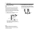
14 INSTALLATION Leveling the Dryer 2 NOTE Adjust the leveling feet only as far as necessary to level the dryer. Extending the leveling feet more than necessary may cause the dryer to vibrate. To ensure that the dryer provides optimal drying performance, it must be level. To minimize vibration, noise, and unwanted movement, the floor must be a perfectly level, solid surface. 1 Position the dryer in the final location. Place a level across the top of the dryer.
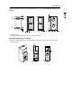
INSTALLATION 15 Reversing the Door 2 While supporting the door, remove the 2 screws on the door hinge. Remove the door. 3 Turn the door upside down and line up the holes in the hinge with the holes on the opposite side of the cabinet. Reinstall the door with the screws removed in step 2.
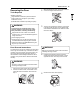
16 INSTALLATION Installing the Side Vent Kit 3 WARNING To reduce the risk of serious injury, death or property damage, follow basic precautions, including the following: Use long-sleeved gloves and safety glasses. Use a heavy metal vent. Preassemble a 4-inch (10.2 cm) elbow to the next 4-inch (10.2 cm) duct section, and secure all joints with duct tape. Be sure that the male end of the elbow faces AWAY from the dryer.
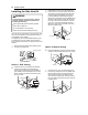
INSTALLATION 17 Stacking the Dryer Stacking Kit Installation This stacking kit includes: To ensure safe and secure installation, please observe the following instructions. 1 Make sure the surface of the washer is clean and dry. Remove paper backing from the tape on one of the stacking kit side brackets. 2 Fit the side bracket to the side of the washer top as shown in the below illustration. Firmly press the adhesive area of the bracket to the washer surface.
18 INSTALLATION Venting the Dryer WARNING To reduce the risk of fire or explosion, electric shock, property damage, injury to persons or death when using this appliance, follow basic safety precautions, including the following: WARNING Ductwork is not provided with the dryer. You should obtain the necessary ductwork locally. The vent hood should have hinged dampers to prevent backdraft when the dryer is not in use. The total length of flexible metal duct must not exceed 8 ft. (2.4 m).
INSTALLATION 19 Routing and Connecting Ductwork Correct Venting NOTE Follow the guidelines below to maximize drying performance and reduce lint buildup and condensation in the ductwork. Ductwork and fittings are NOT included and must be purchased separately. Use 4-inch (10.2 cm) diameter rigid, semi-rigid or flexible metal ductwork. The exhaust duct run should be as short as possible. Use as few elbow joints as possible. The male end of each section of exhaust duct must point away from the dryer.
20 INSTALLATION Connecting the Inlet Hose (Steam Models) WITHOUT WASHER: If the dryer does not share the cold water tap with a washer. a. Connect the straight end of the long hose to the cold water faucet. NOTE Before connecting the water line to the dryer, flush several gallons of water into a drain or bucket. This will help prevent foreign particles such as sand and scale from clogging the dryer inlet valve. NOTE Water supply pressure must be between 20 and 120 psi (138—827 kPa) .
INSTALLATION 21 Connecting Gas Dryers WARNING To reduce the risk of fire or explosion, electric shock, property damage, injury to persons, or death when using this appliance, follow requirements including the following: Electrical Requirements for Gas Models Only Do not, under any circumstances, cut or remove the third (ground) prong from the power cord. For personal safety, this dryer must be properly grounded. This dryer must be plugged into a 120-VAC, 60-Hz.
22 INSTALLATION NOTE In the Commonwealth of Massachusetts: This product must be installed by a licensed plumber or gas fitter. When using ball-type gas shut off valves, they shall be T-handle-type. A flexible gas connector, when used, must not exceed 3 feet. This dryer is configured from the factory for natural gas (NG). If the dryer is to be used with propane (LP) gas, it must be converted by a qualified service technician.
INSTALLATION 23 Connecting Electric Dryers WARNING WARNING To reduce the risk of fire or explosion, electric shock, property damage, injury to persons, or death when using this appliance, follow requirements including the following: Electrical Requirements for Electric Models Only The wiring and grounding must conform to the latest edition of the National Electrical Code, ANSI/NFPA 70 and all applicable local regulations.
24 INSTALLATION Four-Wire Power Cord A 4-wire connection is required for all mobile and manufactured home installations, as well as all new construction after January 1, 1996. 8 Tighten all screws securely. 9 Reinstall the terminal block access cover. Hot (Black) A UL-listed strain relief is required. Neutral (White) Hot (Red) Use a 30-amp, 240-volt, 4-wire, UL-listed power cord with #10 AWGminimum copper conductor and closed loop or forked terminals with upturned ends.
INSTALLATION 25 Four-Wire Direct Wire A 4-wire connection is required for all mobile and manufactured home installations, as well as all new construction after January 1, 1996. 6 Attach the two hot leads of the power cord to the outer terminal block screws. 7 Attach the white neutral wire to the center screw of the terminal block. 8 Attach the power cord ground wire to the green ground screw. 9 Tighten all screws securely. A UL-listed strain relief is required.
26 INSTALLATION Three-Wire Power Cord A 3-wire connection is NOT permitted on new construction after January 1, 1996. 8 Reinstall the terminal block access cover. Hot (Black) Neutral (White) Hot (Red) Ground Screw A UL-listed strain relief is required. Use a 30-amp, 240-volt, 3-wire, UL-listed power cord with #10 AWGminimum copper conductor and closed loop or forked terminals with upturned ends. 1 Remove the terminal block access cover on the upper back of the dryer.
INSTALLATION 27 6 Attach the neutral (white) wire to the center terminal block screw. A UL-listed strain relief is required. 7 Connect the external ground (if required by local codes) to the green ground screw. Use UL-listed 3-wire, #10 AWGminimum copper conductor cable. Allow at least 5 ft. (1.5 m) length to allow for removal and installation of dryer. 8 Tighten all screws securely. 9 Reinstall the terminal block access cover.
28 INSTALLATION Special Electrical Requirements (For Mobile or Manufactured Homes) Any installation in a manufactured or mobile home must comply with the Manufactured Home Construction and Safety Standards Title 24 CFR, Part 3280 or Standard CAN/ CSA Z240 MH and local codes and ordinances. If you are uncertain whether your proposed installation will comply with these standards, please contact a service and installation professional for assistance.
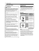
INSTALLATION 29 Installation Test (Duct Check) Once you have completed the installation of the dryer, use this test to make sure the condition of the exhaust system is adequate for proper operation of the dryer. This test should be performed to alert you to any serious problems in the exhaust system of your home. 3 Press the START/PAUSE button. The dryer will start the test, which will last a few minutes. The heat will be turned on and the temperatures in the drum will be measured.