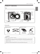
PRODUCT OVERVIEW 9 PRODUCT OVERVIEW ENGLISH Parts Control panel Reversible door Lint filter Leveling feet Power Cord Location (Gas Models) Gas Connection Location (Gas Models) Terminal Block Access Panel (Electric Models) Inlet Valve Exhaust Duct Outlet Accessories Included accessories Y connector Optional accessories Hose Drying rack (3750EL1001A) Side vent kit (sold separately) Kit No. 383EEL9001B NOTE • Visit www.lg.com to purchase accessories.
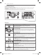
10 PRODUCT OVERVIEW Control Panel Features Following are instructions for starting and using your new dryer. Please refer to specific sections of this manual for more detailed information. wWarning : To reduce the risk of fire, electric shock, or injury to persons, read this entire manual, including the Important Safety Instructions, before operating this dryer. Operation Button Description POWER ON/OFF BUTTON - Press to turn the dryer ON. Press again to turn the dryer OFF.
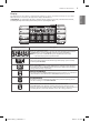
PRODUCT OVERVIEW 11 Display Display and Icons ENGLISH The display shows the settings, estimated time remaining, options, and status messages for your dryer. When the dryer is turned on, the light in the display will illuminate. wWarning : To reduce the risk of fire, electric shock, or injury to persons, read this entire manual, including the Important Safety Instructions, before operating this dryer.
12 INSTALLATION INSTALLATION Installation Overview Checking and choosing the proper location Leveling the dryer Venting the Dryer 120V (Gas) Connecting Gas Dryers (Gas Dryer Type) Connecting Electric Dryers (Electric Dryer Type) 240V(USA) 230V(CANADA) (Electric) Plugging in the power cord and grounding Press and hold Installation test MFL67731085_en_160809.indd 12 Test run 2016.8.
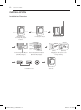
INSTALLATION 13 Installation Location Requirements Read all installation instructions completely before installing and operating your dryer! It is important that you review this entire manual before installing and using your dryer. Detailed instructions concerning electrical connections, gas connections, and exhaust requirements are provided on the following pages. • A location that allows for proper exhaust installation. A gas dryer must be exhausted to the outdoors. See Venting the dryer.
14 INSTALLATION Clearances with Optional Pedestal Base Recommended installation spacing for cabinet installation • For cabinet installation with a door, minimum ventilation openings in the top of the cabinet are required. 7"* (17.8 cm) *Required spacing 7"* (17.8 cm) ** For side or bottom venting, 2 inches (5.1 cm) spacing is allowed. 9"* (22.9 cm) 1"* 27" 5"** 30" (12.7 cm) (76.1 cm) (2.5 cm) (2.5 cm) (68.6 cm) (2.5 cm) 48 in.2 * (310 cm2) 6"* (15.2 cm) 3"* (7.6 cm) 81.6" (207.2 cm) 3"* (7.
INSTALLATION 15 Leveling the Dryer • To reduce the risk of injury to persons, adhere to all industry recommended safety procedures including the use of long sleeved gloves and safety glasses. Failure to follow this warning can cause serious injury or death. 2. U se an adjustable wrench to turn the leveling feet. Turn clockwise to raise the dryer or counterclockwise to lower it. Raise or lower the leveling feet until the dryer is level from side to side and front to back.
16 INSTALLATION Reversing the door wWarning THE DRYER DOOR IS VERY LARGE AND HEAVY. Failure to follow the instructions below can result in damage to the dryer, property damage or injury to persons. • To avoid damage to the dryer or the door, support the door with a stool or box that fits under the door, or have an assistant support the weight of the door. • Always reverse the door BEFORE stacking the dryer on top of the washer. • Avoid dropping the door to avoid damage to the door or the floor. 1.
INSTALLATION 17 Reversing the door (cont.) 10. Insert the four decorative screws on the right side. Decorative Hinge Screw ENGLISH wWarning THE DRYER DOOR IS VERY LARGE AND HEAVY. Failure to follow the instructions below can result in damage to the dryer, property damage or injury to persons. • To avoid damage to the dryer or the door, support the door with a stool or box that fits under the door, or have an assistant support the weight of the door.
18 INSTALLATION Installing the Side Vent Kit wWarning • Use a heavy metal vent. • Do not use plastic or thin foil duct. • Clean old ducts before installing this dryer. • To reduce the risk of injury to persons, adhere to all industry recommended safety procedures including the use of long sleeved gloves and safety glasses. • Failure to follow all of the safety warnings in this manual could result in property damage, injury to persons, or death. 3. P reassemble a 4-inch (10.
INSTALLATION 19 Venting the Dryer To reduce the risk of fire, electric shock, or injury to persons when using this appliance, follow basic precautions, including the following: • Do not crush or collapse ductwork. Failure to follow these instructions can result in fire or death. • Do not allow ductwork to rest on or contact sharp objects. Failure to follow these instructions can result in fire or death.
20 INSTALLATION Venting the Dryer (cont.) Ductwork Wall Cap Type Number of 90° Elbows Maximum Length of 4-inch Diameter Rigid Metal Duct Recommended 0 65 ft. (19.8 m) 1 55 ft. (16.8 m) 2 47 ft. (14.3 m) 3 36 ft. (11.0 m) 4 28 ft. (8.5 m) 0 55 ft. (16.8 m) 1 47 ft. (14.3 m ) 2 41 ft. (12.5 m) 3 30 ft. (9.1 m) 4 22 ft. (6.7 m) 4” (10.2 cm) 4” (10.2 cm) Use only for short run installations 22/4” (6.35 cm) Correct Venting Incorrect Venting NOTE educt 6 ft. (1.
INSTALLATION 21 Connecting the Inlet Hose NOTE • Water supply pressure must be between 20 psi and 120 psi (138–827 kPa). • Do not strip or cross-thread when connecting the inlet hose to the valve. • If the water supply pressure is more than 120 psi (827 kPa), a pressure reducing valve must be installed. • Periodically check the condition of the hose and replace the hose if necessary. • Replace inlet hoses after five years of use to reduce the risk of hose failure.
22 INSTALLATION Connecting Gas Dryers wWarning To reduce the risk of fire, electric shock, or injury to persons when using this appliance, follow basic precautions, including the following: • Gas supply requirements: As shipped from the factory, this dryer is configured for use with natural gas. It can be converted for use with LP (Liquefied Propane) gas. Gas pressure must not exceed 13 inches of water column. • A qualified service or gas company technician must connect the dryer to the gas service.
INSTALLATION 23 Connecting Gas Dryers (cont.) Connecting the gas supply To reduce the risk of fire, electric shock, or injury to persons when using this appliance, follow basic precautions, including the following: 1. M ake sure that the gas supply to the laundry room is turned OFF. Confirm that the type of gas available in your laundry room is appropriate for the dryer. The dryer is prepared for Natural Gas with a 3⁄₈ - inch NPT gas connection.
24 INSTALLATION Connecting Electric Dryers wWarning wWarning To help prevent fire, electric shock, serious injury, or death, the wiring and grounding must conform to the latest edition of the National Electrical Code, ANSI/NFPA 70 and all applicable local regulations. Please contact a qualified electrician to check your home’s wiring and fuses to ensure that your home has adequate electrical power to operate the dryer.
INSTALLATION wWarning • Connect the power cord to the terminal block. Connect each power cord wire to the terminal block screw that has the same colored wire. For example, connect the black power cord wire to the terminal block screw with the black wire. Failure to follow these instructions may result in a short, overload, fire or death.
26 INSTALLATION Connecting Electric Dryers (cont.) USA only wWarning • Connect the power cord to the terminal block. Connect each power cord wire to the terminal block screw that has the same colored wire. For example, connect the black power cord wire to the terminal block screw with the black wire. Failure to follow these instructions may result in a short, overload, fire or death.
INSTALLATION wWarning • Connect the power cord to the terminal block. Connect each power cord wire to the terminal block screw that has the same colored wire. For example, connect the black power cord wire to the terminal block screw with the black wire. Failure to follow these instructions may result in a short, overload, fire or death.
28 INSTALLATION Connecting Electric Dryers (cont.) USA only wWarning • Connect the power cord to the terminal block. Connect each power cord wire to the terminal block screw that has the same colored wire. For example, connect the black power cord wire to the terminal block screw with the black wire. Failure to follow these instructions may result in a short, overload, fire or death.
INSTALLATION Any installation in a manufactured or mobile home must comply with the Manufactured Home Construction and Safety Standards Title 24 CFR, Part 3280 or Standard CAN/CSA Z240 MH and local codes and ordinances. If you are uncertain whether your proposed installation will comply with these standards, please contact a service and installation professional for assistance. • A gas dryer must be permanently attached to the floor.
30 INSTALLATION Installation Test (Duct Check) Once you have completed the installation of the dryer, use this test to make sure the condition of the exhaust system is adequate for proper operation of the dryer. This test should be performed to alert you to any serious problems in the exhaust system of your home. • Your dryer features Flow SenseTM, an innovative sensing system that automatically detects blockages and restrictions in dryer ductwork.
INSTALLATION 31 Installation Test (Duct Check) (cont.) ENGLISH • Check the Error Code before you call for service Error Code Possible Causes tE1 or tE2 • Temperature sensor failure • Turn off the dryer and call for service. • Humidity Sensor failure. • Turn off the dryer and call for service. • Electric dryer power cord is not connected correctly, or house power supply is incorrect. • Check the power supply or the connection of power cord to the terminal block.