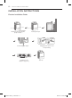
2 INSTALLATION INSTRUCTIONS INSTALLATION INSTRUCTIONS Preview Installation Order Checking and choosing the proper location Leveling the dryer Venting the dryer 120V Connecting gas dryers 240V(USA) 230V(CANADA) Plugging in the power cord and grounding Press and hold Installation test (Refer to page 29.) MFL67731058_en_150529.indd 12 Test run 2015.5.
INSTALLATION INSTRUCTIONS 13 Installation Location Requirements Read all installation instructions completely before installing and operating your dryer! It is important that you review this entire manual before installing and using your dryer. Detailed instructions concerning electrical connections, gas connections, and exhaust requirements are provided on the following pages. • A location that allows for proper exhaust installation. A gas dryer must be exhausted to the outdoors. See Venting the dryer.
23" (58,5 cm) 14 INSTALLATION INSTRUCTIONS 54 2⁄4 (138 cm Clearances (cont.) Recommended Installation Spacing For Cabinet Installation • For cabinet installation with a door, minimum ventilation openings in the top of the cabinet are required. 7"* (17.8 cm) *Required spacing 7"* (17.8 cm) **For side or bottom venting, 2 inches (5.1 cm) clearance is allowed. 312⁄4" 1"* 5"* (12.7 cm) (79.5 cm) (2.5 cm) 1" 29" (2.5 cm) (73.6 cm) 1" (2.
INSTALLATION INSTRUCTIONS 15 Reversing the Door NOTE The door reversal procedure for the two-way door is far more complex than for a conventional dryer door. It is recommended that you read through these instructions in their entirety before beginning the process, in order to gauge whether you prefer to have the procedure done by a professional installer or service person.
16 INSTALLATION INSTRUCTIONS Reversing the Door (continued) hinge cover latch mechanism hinge upper hinge latch hole cover hinge bracket ON THE DOOR: 4. Lift off the door cover. With the door laid inside facing up on a protected surface, remove the 12 screws on the inside of the door. Carefully lift off the door cover with the help of a small flat blade screwdriver inserted in the upper corner (circled below). wWarning The edges of the door cover may be sharp.
INSTALLATION INSTRUCTIONS 17 Reversing the Door (continued) ENGLISH 6. Reverse the components inside the door. You will now be removing and reversing various components inside the door. See below for a detailed diagram and identification of the inner structure and parts of the door. (The diagram shows the “before view” of the door, with the default set-up for a right side hinge swing. After following these instructions, your door should be a mirror image of the illustration.
18 INSTALLATION INSTRUCTIONS Reversing the Door (continued) 7. Lift out the two top interlock buttons. Lift out the two grey interlock buttons from the top of the outer door and set them aside for later use. interlock buttons side lock rod 8. Lift out the grey interlock button in the side of the door. Make sure to remove the spring with the interlock button and to keep the two together. Set the interlock button aside. Do not confuse with interlock buttons from the top of the outer door. b.
INSTALLATION INSTRUCTIONS 19 Reversing the Door (continued) b. Rotate the lower hinge assembly 180 degrees and install it on the right side using the two screws removed in step a. screws ENGLISH N ow rotate the hinge filler 180 degrees and install it on the upper left side of the door. upper hinge filler 13. R einstall the top lock rod. Rotate the top lock rod (removed in step 10) 180 degrees end for end from its original position and reinstall it.
20 INSTALLATION INSTRUCTIONS Reversing the Door (continued) Make sure the top of the side lock rod is beside the top lock rod and the two do not overlap each other, so the two rods can interact correctly. If they are not aligned properly, the door will not operate properly. interlock buttons bumpers 16. Reinstall the top interlock buttons. Reinstall the top gray interlock buttons removed in step 7, one on each side of the outer door panel. 17. Reinstall the side interlock button.
INSTALLATION INSTRUCTIONS 21 Installing the Side Vent Kit • Use a heavy metal vent. • Do not use plastic or thin foil duct. • Clean old ducts before installing this dryer. • To reduce the risk of injury to persons, adhere to all industry recommended safety procedures including the use of long sleeved gloves and safety glasses. • Failure to follow all of the safety warnings in this manual could result in property damage, injury to persons, or death. 3. Preassemble a 4-inch (10.
22 INSTALLATION INSTRUCTIONS Venting the Dryer wWarning To reduce the risk of fire, electric shock, or injury to persons when using this appliance, follow basic precautions, including the following: • Do not crush or collapse ductwork. Failure to follow these instructions can result in fire or death. • Do not allow ductwork to rest on or contact sharp objects. Failure to follow these instructions can result in fire or death.
INSTALLATION INSTRUCTIONS 23 Venting the Dryer (cont.) Wall Cap Type Number Of 90° Elbows Maximum Length Of 4-inch Diameter Rigid Metal Duct Recommended 0 65 ft. (19.8 m) 1 55 ft. (16.8 m) 2 47 ft. (14.3 m) 3 36 ft. (11.0 m) 4 28 ft. (8.5 m) 0 55 ft. (16.8 m) 1 47 ft. (14.3 m ) 2 41 ft. (12.5 m) 3 30 ft. (9.1 m) 4 22 ft. (6.7 m) 4” (10.2 cm) 4” (10.2 cm) Use only for short run installations 22/4” (6.
24 INSTALLATION INSTRUCTIONS Connecting the Inlet Hose The dryer must be connected to the cold water tap using the new water supply hose. Do not reuse old hoses. NOTE • Water supply pressure must be between 20 psi and 120 psi (138–827 kPa). • Do not strip or cross-thread when connecting inlet hose to the valve. • If the water supply pressure is more than 120 psi (827 kPa), a pressure reducing valve must be installed. • Periodically check the condition of the hose and replace the hose if necessary.
INSTALLATION INSTRUCTIONS 25 Connecting Gas Dryers To reduce the risk of fire, electric shock, or injury to persons when using this appliance, follow basic precautions, including the following: • Gas supply requirements: As shipped from the factory, this dryer is configured for use with natural gas. It can be converted for use with LP (Liquefied Propane) gas. Gas pressure must not exceed 13 inches of water column. • A qualified service or gas company technician must connect the dryer to the gas service.
26 INSTALLATION INSTRUCTIONS Connecting Gas Dryers (cont.) wWarning Connecting the gas supply To reduce the risk of fire, electric shock, or injury to persons when using this appliance, follow basic precautions, including the following: 1. M ake sure that the gas supply to the laundry room is turned OFF. Confirm that the type of gas available in your laundry room is appropriate for the dryer. The dryer is prepared for Natural Gas with a 3⁄₈ - inch NPT gas connection.
INSTALLATION INSTRUCTIONS 27 Connecting Electric Dryers wWarning To help prevent fire, electric shock, serious injury, or death, the wiring and grounding must conform to the latest edition of the National Electrical Code, ANSI/NFPA 70 and all applicable local regulations. Please contact a qualified electrician to check your home’s wiring and fuses to ensure that your home has adequate electrical power to operate the dryer.
28 INSTALLATION INSTRUCTIONS Special Requirements for Manufactured or Mobile Homes Any installation in a manufactured or mobile home must comply with the Manufactured Home Construction and Safety Standards Title 24 CFR, Part 3280 or Standard CAN/CSA Z240 MH and local codes and ordinances. If you are uncertain whether your proposed installation will comply with these standards, please contact a service and installation professional for assistance. • A gas dryer must be permanently attached to the floor.
INSTALLATION INSTRUCTIONS 29 Installation Test (Duct check) • Your dryer features Flow Sense™, an innovative sensing system that automatically detects blockages and restrictions in dryer ductwork. Keeping ductwork clean of lint buildup and free of restrictions allows clothes to dry faster and reduces energy use. 4. C heck the display for results. During the three minute test cycle, monitor the Flow Sense™ display on the control panel.
30 INSTALLATION INSTRUCTIONS Installation Test (Duct check) (cont.) • Check the error code before you call for service Error Code tE1 or tE2 HS PS or PF or nP Possible Causes Solutions • T emperature sensor failure • T urn off the dryer and call for service. • Humidity sensor failure. • Turn off the dryer and call for service. • Electric dryer power cord is not connected correctly, or house power supply is incorrect.