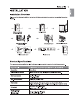
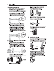
INSTALLATION 8 INSTALLATION Installation Overview Please read the following installation instructions first after purchasing this product or transposing it te another location. Check and choose the proper location wpe & Connect the Inlet hose Connect gas dryers Connect electric dryers (steam mod sis) Hes, =» E65 = ) Electric dryer Plug in the power cord Installation teat Product Specifications The appearances and specifications listed in this manual may vary dua to constant product improvements.
48 INSTALLATION Installation Location Requirements Ab WARNING ) Read all installation instructions completely before installing and operating your dryer! It is important that you review this entire manual before installing and using your dryer. Metaled instructions concerning electrical connections, gas connections, and exhaust requirements are provided on the following pages. The installation requires: = A location that allows for proper exhaust installation. A gas dryer must be exhausted to the outdoors.
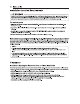
INSTALLATION 11 Closet Ventilation Requirements Closets with doors must have both an upper and lower vent to prevent heat and moisture buildup in the closet, One upper vent opening with a minimum opening (310 om") must be installed no lower than § fest above the floor. One lower vent opening with a minimum opening (158 cn’) must be installed no more than one foot above the Door. Install vent grills in the door or cut down the door at the top and bottom to form openings.
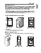
2 INSTALLATION Leveling the Dryer Ab WARNING To reduce the risk of injury to persons, adheres to all industry recommended safely procedures including the use of long-sleeved gloves and safely glasses. Failure to follow this waning may result in serious injury or dash. + The appliance is heavy. Two of more people are required when installing the dryer. Failure fo follow this warming may resell in serous injury or death. © To ensure they the dryer provides optimal drying performance, & must be level.
INSTALLATION 13 Door Reversal Instructions NOTE N The instructions here are for changing the door swing from a right to a lof side hinge. If the door has been reversed, and i is necessary io change it back, use care when hollowing these instructions. Some of the Illustration and the left/ right references will be reversed, and you will need io read the instructions carefully. A) WARNING | Be sure to support the weight of the door before removing the hinge screws.
94 INSTALLATION 7 Reinstall the door. a Reverse the components on the cabinet. While supporting the door, install the four hinge screws removed in tape 2. Test the swing of the door fo make sure the hinges and latch are Hinge Upper properly aligned and that the door opens, closes cover tinge and latches properly in both directions. oath Latch mechanism hols VET Hinge Hinge bracket a.Use a Phipps screwdriver fo remove the two screws and the latch mechanism on the Fran pane! of the cabinet. b.
INSTALLATION 15 Remove the thees screws on the hings st the bottom lef. Remove the hinge an reinstall if on the right SIDS. The top screw will occupy the hole where you removed the screw behind the hinge bracket in step d. 1. install the hinge bracket removed in step don the bottom lef side, first installing one screw behind the hinges bracket. Cabins Revers! complete latch hole cover hinge bracket ON THE DOOR: 4 LIF off the door cover.
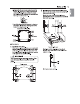
46 INSTALLATION & Reverse the components Inside the door. You will now be removing and reversing various components inside the door. See below for a defiled diagram and identification of the inner structure and parts of the door. (The diagram shows the “before view” of the door, with the default set-up for a right side hinge swing.
INSTALLATION 17 7 Lift out the gray Interlock button In the side of the door. Hake sure to remove the spring with the interior button and to keep the two together. Set the interlock button aside. Do not confuse these with the interlock buttons from the op of the outer door. # Remove the side lock red. Remove the side lock rod from the lower hinge bracket by lifting the top end of the rod and sliding it toward the top of the door. The spring should remain attached to the lock rod. Sat the look rod aside. a.
48 INSTALLATION 4 2 Reinstall the top lock rod. Rotate the fop lock rod (removed in step 10) 180 degrees end for end from its original position and reinstall 8. The spring should now be to the right of center, with the spring on the aids of the rod facing the lop of the door. a.insert the right end of the lock rod into the right hinge assembly. Marks sure the rod is aligned with the guides in the door panel. b.
INSTALLATION 18 15 16 Reinstall the side Interlock button. Reinstall the side interlock bunion removed in step 7. Center the spring in the compartment and instar the interlock button on top Reinstall the door cover. Clean the glass on the door and door cover, if necessary. Wake sure the thees gray interlock bunions are property installed and that the top and side lock rods are properly aligned where they meet.
20 INSTALLATION Installing the Side Vent Kit Ab WARNING « Use a heavy metal vent. » Do not use plastic or thin foil ducts. = Clean old ducts before installing this dryer. » To reduce the risk of injury io persons, adhere to ali industry recommended safely procedures including the use of long-sleeved gloves and safely glasses. + Failure to follow all of the safety wakings in this manual could result in properly damage. injury to parsons, or death. Your new dryer is shipped to vent fo the rear.
INSTALLATION 21 Venting the Dryer 4h WARNING To reduce the risk of firs or explosion, electric shock, properly damage. injury to persons or death wham using this appliance, follow basic safely precautions, including the following: » Do not crush or eolian duct work. Failure fo follow these instructions may result in fire or death. De not slow duct work to rest on of contact sharp objects. Failure to follow these instructions may result in fire or death.
22 INSTALLATION Routing And Connecting Duct work HOT ~ Follow the guidelines below to maximize drying performance and traduces lint buildup and condensation in the duct work. Duct work and fittings are NOT included and must be purchased separately. » Use 4-inch (10.2 om) diameter rigid, semi-rigid or flexible metal duct work. « The exhaust duct run should be as short as possible. » Lae aa few slow joints as possible. * The male end of each section of exhaust duct rust point away from the dryer.
INSTALLATION 23 Connecting the Inlet Hose {Steam Models} The dryer must be connected io the cold water tap using a new water supply hose. Do not use old hoses. NOTE \ +» Water supply pressure must be between 20 and 120 pai (138827 kPa) . + Do not strip or cross-thread when connecting the inst hose to the valve. If the water supply pressure is omen than 800 kPa, a pressure-reducing valve should be installed. Periodically check the condition of the hose and replace the hiss if necessary.
24 INSTALLATION Connecting Gas Dryers 4h WARNING To reduce the risk of firs or explosion, electric shock, properly damage, injury to persons, of death wham using this appliance, follow basic | safely precautions. Gas Supply Requirements « As shipped from the factory, this dryer ls configured for use with nature! gas (NG). canal be converted for use with propane (LP) gas. Gas pressure must not exceed 8-ch {20.3 om) warts column for NG, or 13-inch {33 am) water column for LP.
INSTALLATION 28 Connecting the Gas Supply installation and service must be performed by a qualified Installer, sarcastic agency, or the ges supplier. Failure to do so may result in fire, explosion, or death. Use only a new stainless cites! Irascible connector and a new AHA-certifled connector. Failure to de so may result in fire, explosion, of death. A gas shutoff valve must be installed within 6 ft. {1.8 mi} of the dryer. Failure fo do so may result in fire, explosion, or death.
26 INSTALLATION Connecting Electric Dryers Electrical Requirements for Electric Models Only ~ 4), WARNING . To help prevent fire, electric shock, serious injury, of death, the wiring and grounding must conform to the latest edition of the Nation! Electrical Code, ANSHAN 70 and afl applicable local regulations. Please contact a qualified electrician to check your home's wiring and fuss i ensure they your home has ad equals electrical power to operate the dryer.
INSTALLATION 27 — A) WARNING Connect the power cons to the terminal block. Sch colored wire should be connected to the mass color screw. Wire color indicated on manual is connected fo the same color sower in the block. Failure to follow these instructions may resultant short or overload. Grounding through the neutral conductor is prohibited for: {1} new branch-circuit installations, {2) mobile homes, (3) recreational vehicles, and (4) areas where local codes prohibit grounding through the neutral conductor.
28 INSTALLATION Four-Wire Direct Wire * A-wire connection is required for all mobile and manufactured home installations, as well as all new construction lefter January 1, 1988. + A U Listed rein relief is required. = Use UL-listed 4-wire #10 WAG-minimum copper conductor cable. Allow af least Sf. (1.5 m) of wire to allow for removal and re installation of the dryer. #4 Remove 5-inch {12.7 om) of the rules covering from the wits. Remove 5-inch (12.7 am) of insulation from the ground wire.
INSTALLATION 28 Th res-Wire Power Cord # Reinstall the terminal block across cover, * A S-wire connection iz NOT permitted Hunt Neural an new construction after January 1, (Black) (White) 1998. > Ground 4 + Distillate strain relief is required. Sees » Use 8 30-amp, 240-volt, 3-wire, UL-listed power card with #10 WAG-minimum copper conductor and closed loop or forked terminals with upturned ends. White Vera 4 Remove the millennial block access cover on the from Dry: = > upper back of the dryer.
30 INSTALLATION Th res-Wire Direct Wire * A S-wire connection iz NOT permitted an new construction after January 1, 1988. + Au Listed brain relief is required. = Use UL-listed 3-wire, #10 WAG-minimum copper conductor cable. Allow at least 5. {1.5 m} length 1o allow for removal and installation of dryer. 4 Remove (8.9 on of the outer covering from the wits. Strip 1 inch (2.5 am} insulation from each wire. Bend the ends of the three wires into a hook saps.
INSTALLATION 31 Installation Test (Duct Check] 4 check the display for resits. During the test cycle, monitor the Flow Sanse™ Once you have completed the installation of the display on the control panel. if no bars are dryer, usa this fest to make sure the condition of the displayed, when the cycle ends, the exhaust exhaust system is adequate for proper operation of system is adequate. if the exhaust system is the dryer.
32 INSTALLATION = Check the duct condition if the Flow Sense™ LED is loomed on, check the exhaust system for restrictions and damage. Repair of replace the exhaust system es needed. ~~ NOTE When the dryer is first installed, this lest should be performed to alert you to any existing problems with the exhaust duct in your homes.