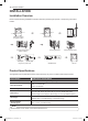
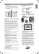
PRODUCT OVERVIEW 9 ENGLISH PRODUCT OVERVIEW Parts Reversible door Control panel Lint filter Leveling feet Accessories Power cord location (gas models) Terminal block access panel (electric models) Gas connection location (gas models) Water inlet valve (on some models) Exhaust duct outlet Two-Way Reversible Door (on some models) Included Accessories Release Y connector Hoses Safety Tether Kit (on some models) (steam models) (steam models) Optional Accessories Hamper door Drying rack (sold separa
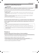
10 INSTALLATION INSTALLATION Installation Overview Please read the following installation instructions first after purchasing this product or transporting it to another location.
INSTALLATION 11 ENGLISH Installation Location Requirements Warning Read all installation instructions completely before installing and operating the dryer! It is important that you review this entire manual before installing and using the dryer. Detailed instructions concerning electrical connections, gas connections, and exhaust requirements are provided on the following pages. The installation requires: •• A location that allows for proper exhaust installation.
12 INSTALLATION Closet Ventilation Requirements Closets with doors must have both an upper and lower vent to prevent heat and moisture buildup in the closet. One upper vent opening with a minimum opening of 48 sq. in. (310 cm2) must be installed no lower than 6 feet above the floor. One lower vent opening with a minimum opening of 24 sq. in. (155 cm2) must be installed no more than one foot above the floor. Install vent grills in the door or cut down the door at the top and bottom to form openings.
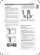
INSTALLATION 13 2 Warning To reduce the risk of injury to persons, adhere to all industry recommended safety procedures including the use of long-sleeved gloves and safety glasses. Failure to follow this warning may result in serious injury or death. Use an adjustable wrench to turn the leveling feet. Unscrew the legs to raise the dryer or screw in the legs to lower it. Raise or lower with the leveling feet until the dryer is level from side to side and front to back.
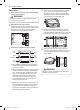
14 INSTALLATION Swing door 1 Open the door from the side so that the hinge screws are accessible. 4 Warning Be sure to support the weight of the door before removing the hinge screws. 2 Remove the four hinge screws. While supporting the door, remove the four hinge screws, two from each hinge. Set the door aside face down on a protected surface to prevent damage to the door or the work surface.
INSTALLATION 15 Reinstall the door. While supporting the door, install the four hinge screws removed in step 2. Test the swing of the door to make sure the hinges and latch are properly aligned and that the door opens, closes and latches properly. 2 Remove the door from cabinet. a. W hile supporting the door, remove the four hinge screws. Two large screws ENGLISH 7 Two small screws b. L ift the door slightly to disengage the hinge support and remove the door from the cabinet.
16 INSTALLATION Twelve screws CAUTION Do NOT remove any of the eight screws on the face of the cabinet (marked below). Doing so could result in damage to the dryer and the need for a service call to repair the dryer. Hole plug e. Remove the three screws on the hinge at the bottom left. Remove the hinge and reinstall it on the right side. The top screw will occupy the hole where you removed the screw behind the hinge bracket in step d. 5 Side Interlock button Switch the door strike and the blank cover.
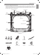
INSTALLATION 17 Reverse the components inside the door. You will now be removing and reversing various components inside the door. See below for a detailed diagram and identification of the inner structure and parts of the door. (The diagram shows the “before view” of the door, with the default set-up for a right side hinge swing. After following these instructions, the door should be a mirror image of the illustration.
18 INSTALLATION 7 Lift out the gray interlock button in the side of the door. Make sure to remove the spring with the interlock button and to keep the two together. Set the interlock button aside. Do not confuse this with the interlock buttons from the top of the outer door. 8 Remove the side lock rod. Remove the side lock rod from the lower hinge bracket by lifting the top end of the rod and sliding it toward the top of the door. The spring should remain attached to the lock rod.
INSTALLATION 19 Reverse the lower hinge bracket and hinge assembly. a. Remove one screw from the lower hinge bracket (on the right) and lift it out. Remove two screws from the lower hinge assembly (on the left) and lift it out. 11 Install the side lock rod. a. F lip the side lock rod over and insert the lower end into the left hinge bracket. b. L ower the rod into the guides on the door while compressing the spring inside the recess.
20 INSTALLATION 12 Reinstall the side interlock button. Install the side interlock button on the opposite side from which it was removed. NOTE Make sure the spring is on the interlock button and is centered in the compartment. 13 Reinstall the door cover. a. Clean the glass on the door and door cover, if necessary. b. Make sure the three gray interlock buttons are properly installed and that the top and side lock rods intersect properly. c.
INSTALLATION 21 3 Warning •• Use a heavy metal vent. •• Do not use plastic or thin foil ducts. •• Clean old ducts before installing this dryer. •• To reduce the risk of injury to persons, adhere to all industry recommended safety procedures including the use of long-sleeved gloves and safety glasses. •• Failure to follow all of the safety warnings in this manual could result in property damage, injury to persons, or death. Preassemble a 4-inch (10.2 cm) elbow to the next 4-inch (10.
22 INSTALLATION Venting the Dryer Warning To reduce the risk of fire or explosion, electric shock, property damage, injury to persons or death when using this appliance, follow basic safety precautions, including the following: •• Do not crush or collapse ductwork. Failure to follow these instructions may result in fire or death. •• Do not allow ductwork to rest on or contact sharp objects. Failure to follow these instructions may result in fire or death.
INSTALLATION 23 NOTE Follow the guidelines below to maximize drying performance and reduce lint buildup and condensation in the ductwork. Ductwork and fittings are NOT included and must be purchased separately. •• Use 4-inch (10.2 cm) diameter rigid, semi-rigid or flexible metal ductwork. ENGLISH Routing And Connecting Ductwork •• The exhaust duct run should be as short as possible. •• Use as few elbow joints as possible. •• The male end of each section of exhaust duct must point away from the dryer.
24 INSTALLATION Connecting the Inlet Hose (Steam Models) d. Connect the long dryer hose to one side of the Y-connector and connect the washer hose to the other side. The dryer must be connected to the cold water tap using a new water supply hose. Do not use old hoses. NOTE •• Water supply pressure must be between 20 and 120 psi (138—827 kPa) . •• Do not strip or cross-thread when connecting the inlet hose to the valve.
INSTALLATION 25 Warning To reduce the risk of fire or explosion, electric shock, property damage, injury to persons, or death when using this appliance, follow basic safety precautions. Gas Supply Requirements •• As shipped from the factory, this dryer is configured for use with natural gas (NG). It can be converted for use with propane (LP) gas. Gas pressure must not exceed 8 inches (20.3 cm) of water column for NG, or 13 inches (33 cm) of water column for LP.
26 INSTALLATION Connecting the Gas Supply •• Installation and service must be performed by a qualified installer, service agency, or the gas supplier. Failure to do so may result in fire, explosion, or death. •• Use only a new stainless steel flexible connector and a new AGA-certified connector. Failure to do so may result in fire, explosion, or death. •• A gas shutoff valve must be installed within 6 ft. (1.8 m) of the dryer. Failure to do so may result in fire, explosion, or death.
INSTALLATION 27 Electrical Requirements for Electric Models Only Warning To help prevent fire, electric shock, serious injury, or death, the wiring and grounding must conform to the latest edition of the National Electrical Code, ANSI/NFPA 70 and all applicable local regulations. Please contact a qualified electrician to check your home’s wiring and fuses to ensure that your home has adequate electrical power to operate the dryer.
28 INSTALLATION Warning Connect the power cord to the terminal block. Connect each wire in the power cord to the terminal block screw with the matching colored wire. The terminal block wire colors are indicated in the manual. Failure to follow these instructions may result in a short or overload.
INSTALLATION 29 •• A UL-listed strain relief is required. •• Use UL-listed 4-wire #10 AWG-minimum copper conductor cable. Allow at least 5 ft. (1.5 m) of wire to allow for removal and reinstallation of the dryer. 1 Remove 5 inches (12.7 cm) of the outer covering from the wire. Remove 5 inches (12.7 cm) of insulation from the ground wire. Cut off approximately 1½ inches (3.8 cm) from the other three wires and strip 1 inch (2.5 cm) of insulation from each wire.
30 INSTALLATION 5 Warning Connect the power cord to the terminal block. Connect each wire in the power cord to the terminal block screw with the matching colored wire. The terminal block wire colors are indicated in the manual. Failure to follow these instructions may result in a short or overload.
INSTALLATION 31 9 Reinstall the terminal block access cover. Hot (Black) •• A 3-wire connection is NOT permitted on new construction after January 1, 1996. •• A UL-listed strain relief is required. •• Use UL-listed 3-wire, #10 AWG-minimum copper conductor cable. Allow at least 5 ft. (1.5 m) length to allow for removal and installation of dryer. 1 Remove 3½-inch (8.9 cm) of the outer covering from the wire. Strip 1 inch (2.5 cm) insulation from each wire.
32 INSTALLATION Installation Test (Duct Check) 4 Once you have completed the installation of the dryer, use this test to make sure the condition of the exhaust system is adequate for proper operation of the dryer. This test should be performed to alert you to any serious problems in the exhaust system of your home. •• This dryer features Flow Sense™, an innovative sensing system that automatically detects blockages and restrictions in dryer ductwork.
INSTALLATION 33 Restricted or Blocked Airflow Avoid long runs or runs with multiple elbows or bends. ENGLISH •• Check the duct condition If the Flow SenseTM LED is turned on, check the exhaust system for restrictions and damage. Repair or replace the exhaust system as needed. NOTE When the dryer is first installed, this test should be performed to alert you to any existing problems with the exhaust duct in your home.
34 OPERATION OPERATION WARNINg To reduce the risk of fire, electric shock, or injury to persons, read this entire manual, including the IMPORTANT SAFETY INSTRUCTIONS, before operating this dryer. Using the Dryer Lint Filter 1 Clean the Lint Filter If the lint filter has not already been cleaned, lift out the filter and remove the lint from the last load. This will help ensure the fastest and most efficient drying performance.
OPERATION 35 Group Similar Items Always make sure the lint filter is clean before starting a new load; a clogged lint filter will increase drying time. To clean, pull the lint filter straight up and roll any lint off the filter with your fingers. Do not rinse or wash the filter to remove lint. Push the lint filter firmly back into place. See Regular Cleaning for more information. Different fabrics have different care requirements, and some fabrics will dry more quickly than others.
36 OPERATION Using the LG EasyLoadTM Swing Door Use the swing door when unloading, or when loading bulkier items, for easy access to the drum. To open the swing door, grasp the top of the door on the side opposite the hinge and pull. NOTE Make sure the hamper door release is completely closed before using the swing door. Hamper Door (on some models) Use the hamper door when loading.
OPERATION 37 3 2 8 1 7 1 POWER Button Press to turn the dryer ON. Press again to turn the dryer OFF. NOTE Pressing the POWER button during a cycle will cancel that cycle and any load settings will be lost. 2 Time and Status Display The display shows the settings, estimated time remaining, options, and status messages for your dryer. 3 Cycle Option Buttons The option buttons allow you to select additional cycle options.
38 OPERATION 12 11 10 9 14 9 CONTROL LOCK INDICATOR When CONTROL LOCK is set, the CONTROL LOCK indicator will appear and all buttons are disabled except the POWER button. This prevents children from changing settings while the dryer is operating. 10 C ycle Completion Indicator with Check Filter Reminder This portion of the display shows which stage of the drying cycle is currently underway (Dry, Cool).
OPERATION 39 Type STEAM CYCLE Cycle Fabric Type Dry Level Temp Time in Min. Steam FreshTM comforter, shirts, trousers (except especially delicate fabrics) Off High 16 Wrinkle Free comforter, bedding, children’s clothing Off High 22 Heavy Duty jeans, heavyweight items High 54 Bulky comforters, pillows, shirts Medium 55 Antibacterial Do not use this cycle with delicate fabrics. High 70 Low 32 Medium High 55 Low 28 Medium Elec.: 57 Gas: 63 High 25 Adj. Adj.
40 OPERATION Manual dry cycles Sensor dry cycles utilize LG’s unique dual sensor system to detect and compare the moisture level in clothes and in the air and adjust the drying time as needed to ensure superior results. The dryer automatically sets the dryness level and temperature at the recommended setting for each cycle. The estimated time remaining will be shown in the display. NOTE Use dry cycles to select a specific amount I manual GN ES of drying time and a drying temperature.
OPERATION 41 Cycle Modifier Buttons SENSOR DRY cycles have preset settings that are selected automatically. MANUAL DRY cycles have default settings, but you may also customize the settings using the cycle modifier buttons. Press the button for that option to view and select other settings. Cycle Option Buttons The dryer features several additional cycle options to customize cycles to meet individual needs.
42 OPERATION Special Functions Rack Dry Some cycle option buttons also activate secondary functions. These special functions are marked with an asterisk (*). Press and hold the option button marked with the special function to activate it. Use Rack Dry with items, such as wool sweaters, silk, and lingerie, that should dry flat. Rack Dry can also be used with items that should not be tumbled dry, such as gym shoes or stuffed animals.
OPERATION 43 ENGLISH Steam Functions (Steam Models) LG’s new steam technology allows you to inject fabrics with a swirling jet of hot steam to refresh clothes, reduce static, and make ironing easier. Simply select the Steam Fresh™ cycle, or you can add a steam option to selected cycles. Using the Steam Fresh™ Cycle Steam Fresh™ uses the power of steam to quickly reduce wrinkles and odor in fabrics.
44 SMART FUNCTIONS SMART FUNCTIONS Smart ThinQ Application The Smart ThinQ application allows you to communicate with the appliance using a smartphone. Installing Smart ThinQ Application Energy Monitoring The dryer energy usage is affected by the cycles and options so you may see some changes in energy usage from one cycle to another. Settings Set the product nickname and delete product. Search for the LG Smart ThinQ application from the Google Play Store or Apple App Store on a smart phone.
SMART FUNCTIONS 45 This equipment has been tested and found to comply with the limits for a Class B digital device, pursuant to Part 15 of the FCC Rules. These limits are designed to provide reasonable protection against harmful interference in a residential installation. This equipment generates, uses, and can radiate radio frequency energy and, if not installed and used in accordance with the instructions, may cause harmful interference to radio communications.
46 SMART FUNCTIONS Smart Diagnosis™ Function Smart ThinQ Smart Diagnosis™ Should you experience any problems with the appliance, it has the capability of transmitting data via your telephone to the LG Customer Information Center. NFC or Wi-Fi equipped models can also transmit data to a smartphone using the LG Smart ThinQ application.
MAINTENANCE 47 Regular Cleaning Warning To reduce the risk of fire, electric shock, or injury to persons when using this appliance, follow basic precautions, including the following: •• Unplug the dryer before cleaning to avoid the risk of electric shock. Failure to follow this warning may cause serious injury, fire, electric shock, or death. Maintaining Ductwork Vent ductwork should be checked for lint buildup once per month and cleaned at least once per year.