User’s Guide L1730SF Make sure to read the Important Precautions before using the product. Keep the User's Guide(CD) in an accessible place for furture reference. See the label attached on the back cover and quote this information to your dealer when you require service.
Important Precautions This unit has been engineered and manufactured to ensure your personal safety, however improper use may result in potential electrical shock or fire hazards. In order to allow the proper operation of all safeguards incorporated in this display, observe the following basic rules for its installation, use, and servicing. On Safety Use only the power cord supplied with the unit.
Important Precautions On Installation Do not allow anything to rest upon or roll over the power cord, and do not place the display where the power cord is subject to damage. Do not use this display near water such as near a bathtub, washbowl, kitchen sink, laundry tub, in a wet basement, or near a swimming pool. Displays are provided with ventilation openings in the cabinet to allow the release of heat generated during operation.
Important Precautions On Cleaning Unplug the display before cleaning the face of the display screen. Use a slightly damp (not wet) cloth. Do not use an aerosol directly on the display screen because over-spraying may cause electrical shock. When cleaning the product, unplug the power cord and scrub gently with a soft cloth to prevent scratching. Do not clean with a wet cloth or spray water or other liquids directly onto the product. An electric shock may occur.
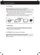
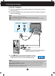
Connecting the Display Before setting up the monitor, ensure that the power to the monitor, the computer system, and other attached devices is turned off. Positioning your display 1. Remove the tape. Put the set as the picture below to remove the tape. Do not remove the tape with the set up side down as the The base part may spring up to injure your hand. 2. Adjust the position of the panel in various ways for maximum comfort.
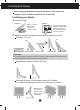
Connecting the Display Using the Computer 1. Connect the signal cable. When attached, tighten the thumbscrews to secure the connection. 2. Connect the power cord into a proper power outlet that is easily accessible and close to the display. NOTE This is a simplified representation of the rear view. This rear view represents a general model; your display may differ from the view as shown.
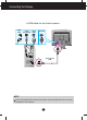
Connecting the Display To Use Touch Screen Select and Install the driver CD provided. Make sure you have the driver installation CD bundled with the product. ITM DRIVER 1) Connect the USB cable for touch screen before installing the driver. 2) Insert the ITM touch screen driver installation CD. 3) See the touch screen software installation CD for more information and assistance. * The software drivers support the following Microsoft Windows operating systems: Windows 2000, XP, VISTA.
Connecting the Display < USB cable for the touch screen > Power Cord Touch Screen USB Signal Cable RS-232C Touch Screen USB NOTE Your purchased product and its accessories may look different from the items illustrated in this manual.
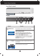
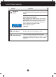
Control Panel Functions Front Panel Controls MENU - + SET/AUTO Bottom Control Function MENU Button Use this button to enter or exit the On Screen Display. OSD LOCKED/UNLOCKED This function allows you to lock the current control settings, so that they cannot be inadvertently changed. Press and hold the MENU button for 5 seconds. The message "OSD LOCKED" should appear. You can unlock the OSD controls at any time by pushing the MENU button for 5 seconds. The message "OSD UNLOCKED" should appear.
Control Panel Functions Control SET/AUTO Button Function Use this button to enter a selection in the On Screen Display. AUTO IMAGE ADJUSTMENT When adjusting your display settings, always press the SET/AUTO button before entering the On Screen Display(OSD). This will automatically adjust your display image to the ideal settings for the current screen resolution size (display mode). The best display mode is 1280x1024 Power Button Use this button to turn the display on or off.
On Screen Display (OSD) Control Adjustment Screen Adjustment Making adjustments to the image size, position and operating parameters of the display is quick and easy with the On Screen Display Control system. A short example is given below to familiarize you with the use of the controls. The following section is an outline of the available adjustments and selections you can make using the OSD.
On Screen Display(OSD) Selection and Adjustment The following table indicates all the On Screen Display control, adjustment, and setting menus.
On Screen Display(OSD) Selection and Adjustment You were introduced to the procedure of selecting and adjusting an item using the OSD system. Listed below are the icons, icon names, and icon descriptions of the all items shown on the Menu. Press the MENU Button, then the main menu of the OSD appears.
On Screen Display(OSD) Selection and Adjustment Main menu Sub menu Description PICTURE PICTURE BRIGHTNESS To adjust the brightness of the screen. CONTRAST To adjust the contrast of the screen. GAMMA Set your own gamma value. : -50/0/50 On the monitor, high gamma values display whitish images and low gamma values display high contrast images. MENU : Exit - : Decrease + : Increase SET : Select another sub-menu COLOR PRESET Select the screen color.
On Screen Display(OSD) Selection and Adjustment Main menu Sub menu Description CLOCK To minimize any vertical bars or stripes visible on the screen background. The horizontal screen size will also change. PHASE To adjust the focus of the display. This item allows you to remove any horizontal noise and clear or sharpen the image of characters. TRACKING TRACKING MENU : Exit SHARPNESS To adjust the clearness of the screen.
On Screen Display(OSD) Selection and Adjustment The OSD screen will appear when you press the monitor. Menu Name button on the front of the Icons Sub-menu Name FLATRON F-ENGINE Screen when applied When you execute F-ENGINE, two tone will appear on the screen as shown in the picture. The applied screen will appear on the left side, whereas the nonapplied screen will appear on the right side.Press the SET button to use the adjusted screen.
Troubleshooting Check the following before calling for service. No image appears Is the power cord of the display connected? Check and see if the power cord is connected properly to the power outlet. Is the power indicator light on? Press the Power button. Is the power on and the power indicator blue or green? Adjust the brightness and the contrast. Is the power indicator amber? If the display is in power saving mode, try moving the mouse or pressing any key on the keyboard to bring up the screen.
Troubleshooting Display image is incorrect Display Position is incorrect. Press the SET/AUTO button to automatically adjust your display image to the ideal setting. If the results are unsatisfactory, adjust the image position using the H position and V position icon in the on screen display. Check Control Panel --> Display --> Settings and see if the frequency or the resolution were changed. If yes, readjust the video card to the recommend resolution.
Troubleshooting Do you see an "Unrecognized monitor, Plug&Play (VESA DDC) monitor found" message? Have you installed the display driver? • Be sure to install the display driver from the display driver CD (or diskette) that comes with your display. Or, you can also download the driver from our web site: http://www.lge.com. • Make sure to check if the video card supports Plug&Play function. Touch screen does not work.
Specifications Display 17 inches (43.2 cm) Flat Panel Active matrix-TFT LCD Anti-Glare coating Visible diagonal size : 43.2 cm 0.264 mm pixel pitch Sync Input Horizontal Freq. Vertical Freq. Input Form Video Input Signal Input 30 - 83kHz (Automatic) 56 - 75Hz (Automatic) Separate Sync Composite Sync SOG (Sync On Green) 15 pin D-Sub Connector Input Form RGB Analog (0.
Specifications Preset Modes (Resolution) Display Modes (Resolution) 1 2 3 4 5 6 7 8 9 10 11 *12 13 VGA VGA VGA VESA VESA VESA MAC VESA VESA MAC VESA VESA VESA Horizontal Freq. (kHz) 31.469 31.468 31.469 37.500 37.879 46.875 49.725 48.363 60.023 68.681 61.805 63.981 79.976 640 x 350 720 x 400 640 x 480 640 x 480 800 x 600 800 x 600 832 x 624 1024 x 768 1024 x 768 1152 x 870 1152 x 900 1280 x 1024 1280 x 1024 Vertical Freq.
Controlling the Multiple Monitors Use this method to connect several monitors to a single PC. You can control several monitors at a time by connecting them to a single PC. Connecting the cable Connect the RS-232C cable as shown in the picture. * The RS-232C protocol is used for communication between the PC and monitor. You can turn the monitor on/off, select an input source or adjust the OSD menu from your PC.
Controlling the Multiple Monitors Command Reference List COMMAND1 01. Power 02. Contrast 03. Brightness 04. Color COMMAND2 k k k k a g h u Transmission / Receiving Protocol Transmission [Command1][Command2][ ][Set ID][ ][Data][Cr] * [Command 1]: First command. * [Command 2]: Second command. * [Set ID]: You can adjust the set ID to choose desired monitor ID number in Setup menu. Adjustment range is 0~ 99. When selecting Set ID ‘0’, every connected monitor set is controlled.
Controlling the Multiple Monitors Transmission / Receiving Protocol Power On (Command:a) To control Power On/Off of the monitor. Transmission [k][a][ ][Set ID][ ][Data][Cr] Data 0 : Power Off 1 : Power On Acknowledgement [a][ ][Set ID][ ][OK][Data][x] To show Power On/Off. Transmission [k][a][ ][Set ID][ ][FF][Cr] Data 0 : Power Off 1 : Power On Acknowledgement [a][ ][Set ID][ ][OK][Data][x] Contrast (Command:g) To adjust screen contrast. You can also adjust contrast in the Contrast/Brightness menu.
Controlling the Multiple Monitors Transmission / Receiving Protocol Brightness (Command:h) To adjust screen brightness. You can also adjust brightness in the Contrast/Brightness menu. Transmission [k][h][ ][Set ID][ ][Data][Cr] Data Min : 0 ~ Max : 64 Refer to ‘Real data mapping’ as shown below. Acknowledgement [h][ ][Set ID][ ][OK][Data][x] * Real data mapping 0 : Step 0 A : Step 10 (SET ID 10) F : Step 15 (SET ID 15) 10 : Step 16 (SET ID 16) 64 : Step 100 Color (Command:U) To adjust the screen color.
Installing the Wall mount plate Wall mount plate (Separate purchase) This is stand-type or wall mount type and is connectable with Wall mount plate. For further information, refer to the VESA Wall Mounting Instruction Guide.
Digitally yours