User’s Guide L1740P L1940P Make sure to read the Important Precautions before using the product. Keep the User's Guide(CD) in an accessible place for furture reference. See the label attached on the back cover and quote this information to your dealer when you require service.
Important Precautions This unit has been engineered and manufactured to ensure your personal safety, however improper use may result in potential eletrical shock or fire hazards. In order to allow the proper operation of all safeguards incorporated in this display, observe the following basic rules for its installation, use, and servicing. On Safety Use only the power cord supplied with the unit.
Important Precautions On Installation Do not allow anything to rest upon or roll over the power cord, and do not place the display where the power cord is subject to damage. Do not use this display near water such as near a bathtub, washbowl, kitchen sink, laundry tub, in a wet basement, or near a swimming pool. Displays are provided with ventilation openings in the cabinet to allow the release of heat generated during operation.
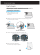
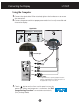
Connecting the Display Using the Computer Before setting up the monitor, ensure that the power to the monitor, the computer system, and other attached devices is turned off. Unfolding the stand base 1. Place the monitor with its front facing downward on a cushion or soft cloth. 2. Hold down the release button inside the stand and strongly pull out the stand with your two hands. The stand won't move if you don't press release button. 3. Connect the signal input cable and the power cord.
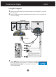
Connecting the Display L1740P Using the Computer 1. Connect the signal cable. When attached, tighten the thumbscrews to secure the connection. 2. Connect the power cord into a proper power outlet that is easily accessible and close to the display.
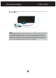
Connecting the Display L1940P Using the Computer 1. Connect the signal cable. When attached, tighten the thumbscrews to secure the connection. 2. Connect the power cord into a proper power outlet that is easily accessible and close to the display.
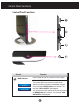
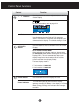
Connecting the Display L1740P/L1940P Touch button for several seconds on the front switch panel to turn the power on. NOTE ‘ Self Image Setting Function’? This function provides the user with optimal display settings.When the user connects the monitor for the first time, this function automatically adjusts the display to optimal settings for individual input signals.
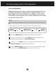
Control Panel Functions Control Panel Functions. Control MENU Button Function Use this button to enter or exit the On Screen Display. OSD LOCKED/UNLOCKED This function allows you to lock the current control settings, so that they cannot be inadvertently changed. Press and hold the MENU button for 5 seconds. The message "OSD LOCKED" should appear. You can unlock the OSD controls at any time by pushing the MENU button for 5 seconds. The message "OSD UNLOCKED" should appear.
Control Panel Functions Control - + Function Buttons Use these buttons to select or adjust functions in the On Screen Display. - Button hot key For more information, refer to page A14 + Button SOURCE hot key Use this button to make Dsub or DVI connector active. This feature is used when two computers are connected to the display. The default setting is Dsub. SET/AUTO Button Use this button to enter a selection in the On Screen Display.
On Screen Display (OSD) Control Adjustment Screen Adjustment Making adjustments to the image size, position and operating parameters of the display is quick and easy with the On Screen Display Control system. A short example is given below to familiarize you with the use of the controls. The following section is an outline of the available adjustments and selections you can make using the OSD. NOTE Allow the display to stabilize for at least 30 minutes before making image adjustments.
On Screen Display(OSD) Selection and Adjustment The following table indicates all the On Screen Display control, adjustment, and setting menus.
On Screen Display(OSD) Selection and Adjustment You were introduced to the procedure of selecting and adjusting an item using the OSD system. Listed below are the icons, icon names, and icon descriptions of the all items shown on the Menu. Press the MENU Button, then the main menu of the OSD appears.
On Screen Display(OSD) Selection and Adjustment Main menu Sub menu Description PICTURE PICTURE BRIGHTNESS To adjust the brightness of the screen. CONTRAST To adjust the contrast of the screen. GAMMA Set your own gamma value. : -50/0/50 On the monitor, high gamma values display whitish images and low gamma values display high contrast images. MENU : Exit - : Decrease + : Increase SET : Select another sub-menu COLOR COLOR PRESET Select the screen color. • 6500K: Slightly reddish white.
On Screen Display(OSD) Selection and Adjustment Main menu Sub menu Description TRACKING TRACKING CLOCK To minimize any vertical bars or stripes visible on the screen background.The horizontal screen size will also change. PHASE To adjust the focus of the display. This item allows you to remove any horizontal noise and clear or sharpen the image of characters.
On Screen Display(OSD) Selection and Adjustment The OSD screen will appear when you touch the right side of the monitor. (-) button on the Menu Name Icons Sub-menu Name FLATRON F-ENGINE Screen when applied Screen when not applied When you execute F-ENGINE, two tones will appear on the screen as shown. The applied screen will appear on the left side, whereas the non-applied screen will appear on the right side.Touch the SETbutton to use the adjusted screen.
Troubleshooting Check the following before calling for service. No image appears Is the power cord of the display connected? Check and see if the power cord is connected properly to the power outlet. Is the power indicator light on? Touch the Power button. Is the power on and the power indicator blue? Adjust the brightness and the contrast. Is the power indicator amber? If the display is in power saving mode, try moving the mouse or pressing any key on the keyboard to bring up the screen.
Troubleshooting Display image is incorrect Display Position is incorrect. Press the SET/AUTO button to automatically adjust your display image to the ideal setting. If the results are unsatisfactory, adjust the image position using the H position and V position icon in the on screen display. Check Control Panel --> Display --> Settings and see if the frequency or the resolution were changed. If yes, readjust the video card to the recommend resolution.
Troubleshooting Have you installed the display driver? Have you installed the display driver? Be sure to install the display driver from the display driver CD (or diskette) that comes with your display. Or, you can also download the driver from our web site: http://www.lge.com. Do you see an "Unrecognized monitor, Plug&Play (VESA DDC) monitor found" message? Make sure to check if the video card supports Plug&Play function.
Specifications Display Sync Input Video Input Resolution Plug&Play Power Consumption Dimensions &Weight (with tilt stand) Tilt Range Power Input Environmental Conditions Tilt Stand Signal cable Power cord L1740P 17 inches (43.2cm) Flat Panel Active matrix-TFT LCD Anti-Glare coating 17 inches viewable 0.264 mm pixel pitch Horizontal Freq. Analog : 30 - 83kHz (Automatic) Digital : 30 - 71kHz (Automatic) Vertical Freq.
Specifications Display Sync Input Video Input Resolution Plug&Play Power Consumption Dimensions &Weight (with tilt stand) Tilt Range Power Input Environmental Conditions Tilt Stand Signal cable Power cord L1940P 19 inches (48.18cm) Flat Panel Active matrix-TFT LCD Anti-Glare coating 19 inches viewable 0.294 mm pixel pitch Horizontal Freq. Analog : 30 - 83kHz (Automatic) Digital : 30 - 71kHz (Automatic) Vertical Freq.
Specifications Preset Modes (Resolution) Display Modes (Resolution) 1 2 3 4 5 6 7 8 9 10 11 12 13 VGA VGA VGA VESA VESA VESA MAC VESA VESA MAC VESA VESA VESA Horizontal Freq. (kHz) 31.469 31.468 31.469 37.500 37.879 46.875 49.725 48.363 60.023 68.681 61.805 63.981 79.976 640 x 350 720 x 400 640 x 480 640 x 480 800 x 600 800 x 600 832 x 624 1024 x 768 1024 x 768 1152 x 870 1152 x 900 1280 x 1024 1280 x 1024 Indicator Mode LED Color On Mode blue Sleep Mode Off Mode amber Off A20 Vertical Freq.
Specifications Signal Connector Pin Assignment 8 16 24 1 9 17 DVI-D Connector Pin 1 2 3 4 5 6 7 8 9 10 11 12 13 14 15 Signal(DVI-D) Pin 16 17 18 19 20 21 22 23 24 T. M. D. S. Data2T. M. D. S. Data2+ T. M. D. S. Data2/4 Shield T. M. D. S. Data4T. M. D. S. Data4+ DDC Clock DDC Data Analog Vertical Sync. T. M. D. S. Data1T. M. D. S. Data1+ T. M. D. S. Data1/3 Shield T. M. D. S. Data3T. M. D. S. Data3+ +5V Power Ground (return for +5V, Signal(DVI-D) Hot Plug Detect T. M. D. S. Data0T. M. D. S. Data0+ T.
How to Install the Rack wall mounting This monitor can be mounted on the VESA standrad wall mounting rack. 1. Please the monitor on a piece of cloth or other soft surface with the front side facing downward and remove the rear cap. 2. Separate the stand base using a screwdriver as shown in the picture. 3. Install the VESA standrad wall mounting. VESA wall mounting Connected to another object (stand type and wall-mounted type. This monitor accepts a VESA-compliant mounting interface pad.
Digitally yours