User’s Guide L1753P L1953P L1753PR L1953PR L1753PM L1953PM Make sure to read the Important Precautions before using the product. Keep the User's Guide(CD) in an accessible place for furture reference. See the label attached on the product and give the information to your dealer when you ask for service.
Important Precautions This unit has been engineered and manufactured to ensure your personal safety, however improper use may result in potential electrical shock or fire hazards. In order to allow the proper operation of all safeguards incorporated in this display, observe the following basic rules for its installation, use, and servicing. On Safety Use only the power cord supplied with the unit.
Important Precautions On Installation Do not allow anything to rest upon or roll over the power cord, and do not place the display where the power cord is subject to damage. Do not use this display near water such as near a bathtub, washbowl, kitchen sink, laundry tub, in a wet basement, or near a swimming pool. Displays are provided with ventilation openings in the cabinet to allow the release of heat generated during operation.
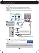
Connecting the speakers - The feature is only for speaker models - L1753PM/L1953PM Connecting the speaker 1. Place the monitor with its front facing downward on a soft cloth. 2. Insert the protruding hook of the speaker in the direction of the slot in the back of the product. Slot Hook AUDIO IN Audio DC-In Cable 3. After setting up the speaker, connect the Audio DC-In Cable to the back of the product.
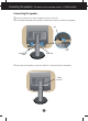
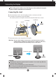
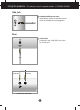
Connecting the Display Before setting up the monitor, ensure that the power to the monitor, the computer system, and other attached devices is turned off. Connecting the stand 1. Place the monitor with its front facing downward on a cushion or soft cloth. 2. Assemble the Stand Base into the Stand Body. Be sure don't pull out the Stop Pin and make the Stand Base direction as shown. Stand Body Side Stand Base Stop Pin FRONT 3. Make the monitor stand , then pull out the Stop Pin.
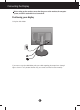
Connecting the Display Before setting up the monitor, ensure that the power to the monitor, the computer system, and other attached devices is turned off. Positioning your display 1. Adjust the position of the panel in various ways for maximum comfort. Tilt Range: -3˚~17˚ -3 Swivel: 356˚ 17 356 Height Range: maximum 5.51 inch (140.0 mm) 140.0 mm First, remove the locking pin. Landscape & Portrait: You can rotate the panel 90˚ clockwise.
Connecting the Display Before setting up the monitor, ensure that the power to the monitor, the computer system, and other attached devices is turned off. Positioning your display Using the cable holder If you want to use the cable holder to let your cables together, please put them through right as shown. For if you don't do like that, you cannot use Pivot function smoothly.
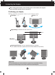
Connecting the Display Using the Computer 1. Place the monitor in a convenient, well-ventilated location near your computer. 2. Connect the signal cable. When attached, tighten the thumbscrews to secure the connection. 1 3. Connect the power cord into a proper power outlet that is easily accessible and close to the display. 2 Signal Cable Power Cord Analog signal Digital signal D-sub DVI Varies according to model. NOTE This is a simplified representation of the rear view.
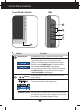
Using the speakers - The feature is only for speaker models - L1753PM/L1953PM Side Jack Headphone/Earphone Input Automatically mutes the speaker volume when the headphones are plugged in. Rear Audio Input Connects to the *LINE OUT jack of the PC sound card.
Control Panel Functions Side Front Panel Controls Control Function MENU Button Use this button to enter or exit the On Screen Display. OSD LOCKED/UNLOCKED This function allows you to lock the current control settings, so that they cannot be inadvertently changed. Press and hold the MENU button for several seconds. The message "OSD LOCKED" should appear. You can unlock the OSD controls at any time by pushing the MENU button for several seconds. The message "OSD UNLOCKED" should appear.
Control Panel Functions Control AUTO/SET Button Function Use this button to enter a selection in the On Screen Display. AUTO IMAGE ADJUSTMENT When adjusting your display settings, always press the AUTO/SET button before entering the On Screen Display(OSD). This will automatically adjust your display image to the ideal settings for the current screen resolution size (display mode). The best display mode is: 1280 x 1024 Power Button Use this button to turn the display on or off.
On Screen Display (OSD) Control Adjustment Screen Adjustment Making adjustments to the image size, position and operating parameters of the display is quick and easy with the On Screen Display Control system. A short example is given below to familiarize you with the use of the controls. The following section is an outline of the available adjustments and selections you can make using the OSD. NOTE Allow the display to stabilize for at least 30 minutes before making image adjustments.
On Screen Display(OSD) Selection and Adjustment The following table indicates all the On Screen Display control, adjustment, and setting menus.
On Screen Display(OSD) Selection and Adjustment You were introduced to the procedure of selecting and adjusting an item using the OSD system. Listed below are the icons, icon names, and icon descriptions of the all items shown on the Menu. Press the MENU Button, then the main menu of the OSD appears.
On Screen Display(OSD) Selection and Adjustment Main menu Sub menu Description PICTURE PICTURE BRIGHTNESS To adjust the brightness of the screen. CONTRAST To adjust the contrast of the screen. GAMMA Set your own gamma value. : -50/0/50 On the monitor, high gamma values display whitish images and low gamma values display high contrast images.
On Screen Display(OSD) Selection and Adjustment Main menu Sub menu Description TRACKING TRACKING CLOCK To minimize any vertical bars or stripes visible on the screen background. The horizontal screen size will also change. PHASE To adjust the focus of the display. This item allows you to remove any horizontal noise and clear or sharpen the image of characters. MENU : Exit : Decrease : Increase SHARPNESS To adjust the clearness of the screen.
On Screen Display(OSD) Selection and Adjustment The OSD screen will appear when you touch the right side of the monitor. button on the Menu Name Icons Sub-menu Name FLATRON F-ENGINE Screen when applied Screen when not applied When you execute F-ENGINE, two tones will appear on the screen as shown. The applied screen will appear on the left side, whereas the non-applied screen will appear on the right side.Touch the SET button to use the adjusted screen.
Troubleshooting Check the following before calling for service. No image appears ● Is the power cord of the • Check and see if the power cord is connected properly to the power outlet. display connected? ● Is the power indicator light on? • Press the Power button. ● Is the power on and the • Adjust the brightness and the contrast.
Troubleshooting Display image is incorrect ● Display Position is incorrect. • Press the AUTO/SET button to automatically adjust your display image to the ideal setting. If the results are unsatisfactory, adjust the image position using the H position and V position icon in the on screen display. • Check Control Panel --> Display --> Settings and see if the frequency or the resolution were changed. If yes, readjust the video card to the recommend resolution.
Troubleshooting Have you installed the display driver? ● Have you installed the display driver? • Be sure to install the display driver from the display driver CD (or diskette) that comes with your display. Or, you can also download the driver from our web site: http://www.lge.com. ● Do you see an "Unrecognized monitor, Plug&Play (VESA DDC) monitor found" message? • Make sure to check if the video card supports Plug&Play function.
Specifications L1753P/L1753PR Display 17 inches (43.2 cm) Flat Panel Active matrix-TFT LCD Anti-Glare coating 17 inches viewable 0.264 mm pixel pitch Sync Input Horizontal Freq. Vertical Freq. Input Form Video Input Signal Input 15 pin D-Sub Connector DVI - D connector (Digital) RGB Analog (0.
Specifications L1953P/L1953PR Display 19 inches (48.19 cm) Flat Panel Active matrix-TFT LCD Anti-Glare coating 19 inches viewable 0.294 mm pixel pitch Sync Input Horizontal Freq. Vertical Freq. Input Form Video Input Signal Input 15 pin D-Sub Connector DVI - D connector (Digital) RGB Analog (0.
Specifications L1753PM Display 17 inches (43.2 cm) Flat Panel Active matrix-TFT LCD Anti-Glare coating 17 inches viewable 0.264 mm pixel pitch Sync Input Horizontal Freq. Vertical Freq.
Specifications Display Sync Input Video Input Resolution Plug&Play Power Consumption (without speaker) Dimensions &Weight L1953PM 19 inches (48.19 cm) Flat Panel Active matrix-TFT LCD Anti-Glare coating 19 inches viewable 0.294 mm pixel pitch Horizontal Freq. Analog : 30 - 83 kHz (Automatic) Digital : 30 - 71 kHz (Automatic) Vertical Freq.
Specifications Preset Modes (Resolution) Display Modes (Resolution) 1 2 3 4 5 6 7 8 9 10 11 *12 **13 VGA VGA VGA VESA VESA VESA MAC VESA VESA MAC VESA VESA VESA Horizontal Freq. (kHz) 31.469 31.468 31.469 37.500 37.879 46.875 49.725 48.363 60.023 68.681 61.805 63.981 79.976 640 x 350 720 x 400 640 x 480 640 x 480 800 x 600 800 x 600 832 x 624 1024 x 768 1024 x 768 1152 x 870 1152 x 900 1280 x 1024 1280 x 1024 Vertical Freq.
Specifications Signal Connector Pin Assignment 8 16 24 1 9 17 DVI-D Connector Pin 1 2 3 4 5 6 7 8 9 10 11 12 13 14 15 Signal(DVI-D) Pin 16 17 18 19 20 21 22 23 24 T. M. D. S. Data2T. M. D. S. Data2+ T. M. D. S. Data2/4 Shield T. M. D. S. Data4T. M. D. S. Data4+ DDC Clock DDC Data Analog Vertical Sync. T. M. D. S. Data1T. M. D. S. Data1+ T. M. D. S. Data1/3 Shield T. M. D. S. Data3T. M. D. S. Data3+ +5V Power Ground (return for +5V, Signal(DVI-D) Hot Plug Detect T. M. D. S. Data0T. M. D. S. Data0+ T.
Installing the Wall mount plate This monitor satisfies the specifications of the Wall mount plate or the interchange device. 1. Place the monitor with its front facing downward on a soft cloth. 2. Separate the stand after firstly separating 4 screws by using a driver as figure. 3. Install the Wall mount plate. Wall mount plate (Separate purchase) This is stand-type or will mount type and is connectable with Wall mount plate.
Digitally yours