
Installation guide


5
INSTALLATION INSTRUCTIONS
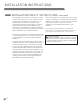
DIMENSIONS AND CLEARANCES
Provide enough clearances between the cooktop
and adjacent combustible surfaces. These dimensions
must be met for safe use of your cooktop.
The location of the electrical outlet and pipe opening
may
be adjusted to meet specific requirements.
The cooktop may be placed with 2 3/4” clearance to
the back wall.
To ensure accuracy, it is best to make
a template when cutting the opening
in the counter
3 3/4 MIN.
F
width
C
width
E
height
G
depth
D
depth
1” Min. From Backwall
From Cutout
Center Line
Recommended
gas supply
location
Wall covering,
cabinets and
countertop
must withstand
heat up to
200°F
MAINTAIN THE FOLLOWING
MINIMUM CLEARANCE
DIMENSIONS
RECOMMENDED GAS SUPPLY
LOCATION FROM BACKWALL
MAKE SURE WALL COVERINGS,
COUNTERTOP AND CABINETS
AROUND COOKTOP CAN
WITHSTAND HEAT(UP TO 200℉)
GENERATED BY COOKTOP
A˝MIN. clearance from
cutout to side wall on
the right of the unit
18˝MIN. height
from countertop
to nearest cabinet
on either side of
unit
A˝MIN. clearance
from cutout to side
wall on the left of
unit.
30˝MIN. clearance
from countertop to
unprotected overhead
surface
13˝MAX. Depth of unprotected
overhead cabinets
COOKTOP AND CUTOUT
DIMENSIONS
K″MIN.
From front
edge of cutout
and front edge
of countertop
MODEL
A
B
C
D
E
F
G
H
J
K L
30″ Cooktop
36″ Cooktop
A
A
B″MIN
L″MIN.
Between
cutout
and the wall
behind the
cooktop
H
width cut
J
depth cut
L
K
11
13
16
″
11
13
16
″
30″
36″
30″
36″
21
11
16
″
21
11
16
″
3
3
4
″
3
3
4
″
28
1
4
″
33
5
8
″
19
3
8
″
19
3
8
″
28
1
2
″
33
15
16
″
19
11
16
″
19
11
16
″
1
5
8
″
1
5
8
″
2
3
4
″
2
3
4
″
1.
3.
4.
2.
C
L