INSTALLATION 13 INSTALLATION Installation Overview Unpacking the Refrigerator Connecting the Water Line CAUTION x Connect to potable water supply only. Choosing the Proper Location Leveling and Door Alignment Disassembling/ Assembling ENGLISH 3OHDVH UHDG WKH IROORZLQJ LQVWDOODWLRQ LQVWUXFWLRQV ¿UVW DIWHU SXUFKDVLQJ WKLV SURGXFW RU WUDQVSRUWLQJ LW WR DQRWKHU location.
14 INSTALLATION Unpacking the Refrigerator WARNING Choosing the Proper Location Water x Use two or more people to move and install the refrigerator. Failure to do so can result in back injury or other injury. Water supply must be easily connected for the automatic icemaker. x 7KH UHIULJHUDWRU LV KHDY\ 3URWHFW WKH ÀRRU ZKHQ moving the refrigerator for cleaning or service. Always pull the refrigerator straight out when moving it.
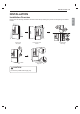
16 INSTALLATION Removing/Assembling Handles x When moving the refrigerator through a narrow opening, removing the doors is preferred. x The appearance of the handles may vary from what is shown. Removing the Refrigerator Handles 1 Loosen the set screws (1) with a 3/32 in. Allen wrench and remove the handle. 2 Loosen the mounting fasteners (2) that connect to the refrigerator door and handle using a 1/4 in. Allen wrench, and remove the mounting fasteners.
INSTALLATION 17 Removing the Freezer Drawer Handle Loosen the set screws (1) located on the lower side of the handle with a 1/8 in. Allen wrench and remove the handle. 2 Loosen the mounting fasteners (2) with a 1/4 in. Allen wrench, and remove the mounting fasteners. If the entrance door is too narrow for the refrigerator to pass through, remove the refrigerator doors and move the refrigerator sideways through the doorway.
18 INSTALLATION 2 Remove the screw (1) from the hinge cover at the top of the refrigerator. Lift the hook (not visible), located at the bottom of the front side of the cover ZLWK D ÀDW KHDG VFUHZGULYHU 5 Lift the door from the middle hinge pin and remove the door. CAUTION x Place the door, inside facing up, on a nonscratching surface. 3 Remove the cover and pull out the tube (1). Disconnect all wire harnesses (2). Unscrew the ground wire (3).
INSTALLATION 19 2 Assembling the Right Refrigerator Door Detach the wire harness (1). ,QVWDOO WKH ULJKW VLGH GRRU ¿UVW Make sure that the plastic sleeve is inserted in the bottom of the door. Lower the door onto the PLGGOH KLQJH SLQ DV VKRZQ LQ WKH ¿JXUH 2 Fit the hinge (1) over the hinge lever latch and slot it into place. Rotate the lever (2) counterclockwise to secure the hinge. Rotate the hinge lever (1) clockwise. Lift the top hinge (2) free of the hinge lever latch.
20 INSTALLATION Assembling the Left Refrigerator Door 5 Install the left refrigerator door after the right door is installed. 1 Hold the water supply connection and gently push in the collet (1) to connect the water supply line (2) as shown. Insert the tube at least 5/8 inch (15 mm) into the connector. Insert the clip on the joint to fasten the tube in place. Make sure that the plastic sleeve is inserted in the bottom of the door. Install the refrigerator door onto the middle hinge.
INSTALLATION 21 Removing the Freezer Drawers For models with two freezer drawers, remove both drawers in the same way. 3 Lift the front of the drawer up, then pull it straight out. 4 Remove the Durabase basket from the rails. Remove the screws from the rails at both ends. 5 Grip both sides of the drawer and pull it up to remove it from the rails. ENGLISH The Pullout Drawer located above the freezer drawer is not shown for clarity.
22 INSTALLATION 6 Hold both rails and push them in simultaneously. Assembling the Freezer Drawer 1 2 3 /RZHU WKH GRRU LQWR LWV ¿QDO SRVLWLRQ DQG WLJKWHQ the screws located on both sides. 4 Push the drawer back until it clicks into place. 5 Replace the ice bin in the drawer. Insert the Durabase basket in the rail assembly. Pull out both rails simultaneously, until they are fully extended. Grasp the drawer on each side and hook the drawer supports into the rail tabs located on both sides.
INSTALLATION 23 Connecting the Water Line Before Beginning If the water pressure from the reverse osmosis system is less than 20 psi or 138 kPa or 1.4 kgf/ cm2 WDNHV PRUH WKDQ VHFRQGV WR ¿OO D FXS RI R] RU 198 cc capacity): x &KHFN WR VHH LI WKH VHGLPHQW ¿OWHU LQ WKH UHYHUVH RVPRVLV V\VWHP LV EORFNHG 5HSODFH WKH ¿OWHU LI necessary. ,I QHFHVVDU\ FDOO D TXDOL¿HG SOXPEHU WR FRUUHFW ZDWHU hammer before installing the water supply line to the refrigerator.
24 INSTALLATION x Shutoff valve to connect to the cold water line. The shutoff valve should have a water inlet with a minimum inside diameter of 5/32 in. at the point of connection to the COLD WATER LINE. Saddle-type shutoff valves are included in many water supply kits. Before purchasing, make sure a saddle-type valve complies with your local plumbing codes. NOTE x A self-piercing saddle type water valve should not be used.
INSTALLATION 25 6 NOTE x %H VXUH WKHUH LV VXI¿FLHQW H[WUD WXELQJ DERXW IW coiled into three turns of about 10 in. diameter) to allow the refrigerator to move out from the wall after installation. 7 Connect the tubing to the valve. Place the compression nut and ferrule (sleeve) for copper tubing onto the end of the tubing and connect it to the shutoff valve. Make sure the tubing is fully inserted into the valve. Tighten the compression nut securely. 9 Connect the tubing to the refrigerator.
26 INSTALLATION Leveling and Door Alignment Door Alignment Leveling Standard Door The refrigerator has two front leveling legs. Adjust the legs to alter the tilt from front-to-back or side-to side. If the refrigerator seems unsteady, or the doors do not close easily, adjust the refrigerator’s tilt using the instructions below: 1 Turn the leveling leg to the left to raise that side of the refrigerator or to the right to lower it.
INSTALLATION 27 The right refrigerator door does not have an adjustable nut. 1 With one hand, lift up both the inner and outer door sections of the right door to raise them at the middle hinge. (It may be easier to lift it with the doors open.) 2 With the other hand, use pliers to insert the snap ring on the middle hinge of the inner door section as shown. Do not insert the ring on the hinge of the outer door section. 3 Insert additional snap rings until the right door is aligned.