IP LDK-20 Installation Manual I PL D K 2 0 INSTALLATION MANUAL
IP LDK-20 Installation Manual REVISION HISTORY ISSUE DATE ISSUE 1.0 ISSUE 1.1 2005.3 2005.
IP LDK-20 Installation Manual TABLE OF CONTENTS ■ IMPORTANT SAFETY INSTRUCTIONS ....................................................... 1 Safety requirements .................................................................................................................... 1 ■ PRECAUTION................................................................................................. 2 ■ THE STRUCTURE OF MANUAL ................................................................... 3 SECTION 1.
IP LDK-20 Installation Manual 4.1 Unpacking............................................................................................................................ 47 4.2 Opening and closing the front cover................................................................................... 48 4.2.1 Opening the front cover .......................................................................................................... 48 4.2.2 Closing the front cover ............................................
IP LDK-20 Installation Manual ■ Introduction Important Safety Instructions Safety requirements When using your telephone equipment, basic safety precautions should always be followed to reduce the risk of fire, electric shock and other personal injury, including the following: • Please read and understand all instructions. • Follow all warnings and instructions marked on the product. • Unplug this product from the wall outlet before cleaning.
IP LDK-20 Installation Manual ■ Introduction Precaution • • • • Keep the system away from heating appliances and electrical noise generating devices such as fluorescent lamps, motors and televisions. These noise sources can interfere with the performance of the IP LDK-20 System. This system should be kept free of dust, moisture, high temperature (more than 40 degrees) and vibration, and should not be exposed to direct sunlight. Never attempt to insert wires, pins, etc. into the system.
IP LDK-20 Installation Manual ■ Introduction The Structure of Manual This installation manual is designed to provide as general information for the IP LDK-20 System. It provides instructions for installing the hardware, and programming the IP LDK-20 System using keyset. This manual contains the following sections: Section 1. Introduction Provides general information on the IP LDK-20 System, including the system specifications and capacity. Section 2.
IP LDK-20 Installation Manual Introduction SECTION 1. INTRODUCTION 1.1 The IP LDK-20 System highlights Features of the IP LDK-20 System include: • Flexible architecture • Optional LAN Interface • Stable & enhanced voice features • Simple installation & efficient system management - Remote admin through BRI connection - Remote admin through PSTN modem - Remote admin through LAN connection • Value-added features - Distinctive voice mail - CID (CO & SLT) - VOIP Service 1.
IP LDK-20 Installation Manual Introduction 1.
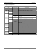
IP LDK-20 Installation Manual Introduction 1.4 Specifications 1.4.1 General specifications ITEM DESCRIPTION SPECIFICATION PSU AC Voltage Input AC Power AC Input Fuse DC Output Voltage 230 +/-10% Volt AC @47-63Hz 90W 1.25A @ 250Volt AC +5, -5, +30Volt DC AC Adaptor AC Voltage Input AC Input Fuse DC Output Voltage 230 +/-10% Volt AC @47-63Hz 1A @ 250Volt AC 48Volt DC Battery Backup Input Voltage Battery Fuse Charging Current Battery Load Current 24 Volt DC 5.0A @ 250Volt AC Max. 100mA Max.
IP LDK-20 Installation Manual Introduction 1.4.2 System Capacity DESCRIPTION CAPACITY/BOARD Time Slots CO Line Ports Max direct Station connections 4/MBUB(BRI) 4/LCOB or 4/STIB 8/VOIM 8/MBUB 8/DTIB or 8/SLIB 8/DTIM, 8 SLIM, or 8/VOIM TOTAL 96 Max. 16 (Analog CO, ISDN BRI and/or IP trunk) Max.
IP LDK-20 Installation Manual KSU Installation SECTION 2. KSU INSTALLATION 2.1 Pre-Installation Please read the following guidelines concerning installation and connection before installing the IP LDK-20 System. Be sure also to comply with applicable local regulations. 2.1.
IP LDK-20 Installation Manual KSU Installation 2.2 KSU Installation 2.2.1 Unpacking Open the box and verify the items shown in Figure 2.2.1 are included: Key service unit Mounting template Power cord Tie cable Manual Battery cable Anchor plug Figure 2.2.
IP LDK-20 Installation Manual KSU Installation 2.2.2 KSU exterior and dimension Figure 2.2.2 shows the exterior and dimensions of the KSU: Figure 2.2.
IP LDK-20 Installation Manual KSU Installation 2.2.3 KSU with expansion module exterior and dimension Figure 2.2.3 shows the exterior and dimensions of the KSU: Figure 2.2.
IP LDK-20 Installation Manual KSU Installation 2.2.4 Opening and closing the front cover 2.2.4.1 Opening the front cover 1. Turn the screw counter-clockwise to loosen as shown in Figure 2.2.4.1. 2. Lift the front cover in the direction of the arrow as shown: Figure 2.2.4.
IP LDK-20 Installation Manual KSU Installation 2.2.4.2 Closing the front cover Insert the front cover into the slot on the KSU as show in Figure 2.2.4.2. Then put the front cover down on the KSU in the direction of the arrow, as shown. Turn the screws clockwise to tighten, as in the Figure. Figure 2.2.4.2 Closing the front cover ※ NOTE For safety reasons, close the front cover and tighten the screws prior to operating the IP LDK-20 System.
IP LDK-20 Installation Manual KSU Installation 2.2.5 Frame ground connection It is very important the frame of the IP LDK-20 system is grounded: 1. Turn the screw counter-clockwise to loosen. Then insert the grounding wire. 2. Tighten the screw. Then connect the grounding wire to ground source as shown in Figure 2.2.5. Figure 2.2.5 Grounding the KSU CAUTION • • • • The equipment should be connected to a socket-outlet with a protective ground connection.
IP LDK-20 Installation Manual KSU Installation 2.2.6 Power Supply Unit (PSU) installation Before installation, make sure that the KSU not plugged into an outlet. The PSU is located at the left-most area of the KSU, and is capable of providing three kinds of power sources to MBUB through the 7PIN connector, CN19 (refer to the following table). The AC Input Voltage and Fuse Rating RANGE OF INPUT VOLTAGE CONNECT TO FUSE RATINGS 207V AC - 253V AC CN19 on the MBUB 1.
IP LDK-20 Installation Manual KSU Installation 2.2.7 External backup batteries installation In case of power failure, the external backup batteries automatically maintain uninterrupted power for the IP LDK-20 system. The external batteries must provide 24 Volts DC. This is generally accomplished by connecting two 12 Volt batteries in a series arrangement. Figure 2.2.7 External Back Up Battery Installation ※ Note : The cable for connecting the battery is supplied with the KSU.
IP LDK-20 Installation Manual KSU Installation 2.2.8 KSU mounting 2.2.8.1 Wall mounting 1. Install 3 anchor plugs in the wall using the mounting template included for accurate placement (Figure 2.2.8.1a). 2. Attach the mounting template with the included 3 screws. 3. Hook the KSU onto the screws, making sure that the system slides down securely (Figure 2.2.8.1b). Figure 2.2.8.
IP LDK-20 Installation Manual KSU Installation Figure 2.2.8.1b KSU Wall Mounting ※ Note : Be careful not to drop the KSU.
IP LDK-20 Installation Manual KSU Installation 2.2.8.2 Rack mounting 1. Attach the rack bracket to the bottom of the IP LDK-20 system as shown in Figure 2.2.8.2a, and attach it to the system securely by tightening the screws clockwise. Figure 2.2.8.2a Rack Bracket 2. To attach the IP LDK-20 system to the rack, affix the bracket with the 4 screws provided (Figure 2.2.8.2b). Figure 2.2.8.
IP LDK-20 Installation Manual Board Installation SECTION 3. BOARD INSTALLATION 3.1 Installation of the Boards Prior to Board Installation, the following should be considered: CAUTION • • • Power must be turned OFF. To protect the system from static electricity, do not touch the boards. To discharge static, touch a grounded object, or wear a grounding strap. Insert boards carefully to avoid bending connector pins (male pins on MBUB). To install the board, perform the following Steps: 1.
IP LDK-20 Installation Manual Board Installation 3.2 MBUB (Main Board Unit) Description The MBUB controls communication between the peripheral interfaces, supervises all resources in the system, controls the gain adjustment of the PCM signal, generates the system tones, and manages system call processing. The MBUB (Figure 3.
IP LDK-20 Installation Manual Board Installation Figure 3.2b Connection The MBUB is installed in the KSU and provides various kinds of connectors and RJ45 modular jacks for the connection of peripheral boards and miscellaneous functions (refer to the following Table).
IP LDK-20 Installation Manual Board Installation 3.2.1 Modular Jack(MJ1~MJ3) Pin Assignment 3.2.1.1 MBUB MJ1(CO) T Mode CONNECTOR PIN NUMBER RJ45 R ON OFF 1 2 3 4 SW5 RJ45 type jack CN2 1,2,7,8 3 4 5 6 TX+ RX+ RXTX- FUNCTION Reserved R 3 TX+ RX+ 3 6 TX- RX- 6 4 RX+ TX+ 4 5 RX- TX 5 ON OFF S SIGNAL NAME Transmit Data Receive Data Receive Data Transmit Data NT1(NT B - OX) BRI Port1 T Interface T NO From/to PX Max.
IP LDK-20 Installation Manual Board Installation S Mode CONNECTOR PIN NUMBER NO SIGNAL NAME 1,2,7,8 3 4 5 6 RJ45 FUNCTION Reserved RX+ TX+ TXRX- Receive Data Transmit Data Transmit Data Receive Data ISDN terminal TE1(or TA) BRI Port1 Only S interface R ON 1 2 3 4 SW5 RJ45 type jack T R 3 RX+ TX+ 3 6 RX- TX- 6 4 TX+ RX+ 4 5 TX- RX- 5 ON S CN21 Max. 1000 meters 1 2 SW7 ON : S mode Figure 3.2.1.
IP LDK-20 Installation Manual - Board Installation CN21: SET FOUR 2PIN JUMPERS AS SHOWN IN THE ABOVE TABLE ACCORDING TO EACH MODE. 3.2.1.
IP LDK-20 Installation Manual Board Installation 5-6 RESERVED 3.2.1.3 MJ4 Pin Assignment MBUB CONNECTOR PIN NUMBER RJ45 NO SIGNAL NAME 1,2 Relay1-R, Relay1-T 3,4 Relay2-R, Relay2-T 5,6 EXT_PAGE-R, EXT_PAGE-T 7,8 Alarm-R, Alarm-T 3.2.1.
IP LDK-20 Installation Manual GREEN Board Installation IN-USE 3.2.1.5 CN22 Pin assignment MBUB CONNECTOR PIN NUMBER RS-232C NO SIGNAL NAME 1 2 3 4 5 6 7 8 9 TD RD DSR SG DTR CTS RTS NO SIGNAL NAME 1 2 3 4 5 6 7 8 9 RD TD DTR SG DSR RTS CTS FUNCTION RESERVED Transmitted Data Received Data Not used Signal Ground Not used Not used Not used RESERVED PC CONNECTOR RS-232C PIN NUMBER ※ NOTE : The MBUB does not support hardware flow control.
IP LDK-20 Installation Manual Board Installation 28
IP LDK-20 Installation Manual Board Installation 3.3 Installation of the CO Line Board BOARD PORT CONNECTOR TYPE LCOB 2 ports (4 LCO) RJ45 Loop Start CO Line Interface 2 wire STIB 2 ports (2 BRI) RJ45 ISDN Basic Rate Interface (2B+D) 4 wire Switched T or S CBIB 2 ports ( 1 BRI+2 LCO) RJ45 ISDN Basic Rate Interface (2B+D) + Loop Start CO Line Interface 4 wire (Port 1) 2 wire (Port 2) T mode only. DESCRIPTION CABLE REMARK 3.3.
IP LDK-20 Installation Manual Board Installation 3.3.1.1 Pin Assignment LCOB CONNECTOR PIN NUMBER RJ45 NO SIGNAL NAME 1,2 CO-R, CO-T 3 Reserved 4,5 CO-R, CO-T 6,7,8 Reserved CONNECTOR FUNCTIONS CONNECTOR CN2 and CN3 CN1, CN2 and CN3 MJ1 FUNCTION REMARK PRCPTU4 or PRU4 connection CPCU4 connection 2 ports RJ45 type CO line connection. 3.3.1.
IP LDK-20 Installation Manual Board Installation PRCPTU4 (PR and CPT detection Unit) Description The PRCPTU4 can be optionally mounted on LCOB, and provides four polarity reversal detection for call metering, four call progress tone detection to support ACNR feature (Automatic Called Number Redial). Figure 3.3.1.
IP LDK-20 Installation Manual Board Installation 3.3.2 STIB (Basic Rate Interface Board: Selectable S/T interface) Description STIB should be installed on the LCOB/STIB/CBIB connector, and supports T-interface or S-interface. The 1st BRI port can be operated to T-mode and S-mode and the 2nd port can only be set to T-mode. Figure 3.3.
IP LDK-20 Installation Manual Board Installation 3.3.2.1 Pin assignment T MODE CONNECTOR PIN NUMBER RJ45 R ON OFF 1 2 3 4 SW4 RJ45 type jack CN1 1,2,7,8 3 4 5 6 TX+ RX+ RXTX- FUNCTION Reserved R 3 TX+ RX+ 3 6 TX- RX- 6 4 RX+ TX+ 4 5 RX- TX 5 ON OFF S SIGNAL NAME Transmit Data Receive Data Receive Data Transmit Data NT1(NT B - OX) STIB Port1 T Interface T NO From/to PX Max.
IP LDK-20 Installation Manual Board Installation S MODE CONNECTOR PIN NUMBER RJ45 NO SIGNAL NAME 1,2,7,8 3 4 5 6 RX+ TX+ TXRX- FUNCTION Reserved Receive Data Transmit Data Transmit Data Receive Data ISDN terminal TE1(or TA) STIB Port1 Only S Interface R ON 1 2 3 4 SW4 RJ45 type jack T R 3 RX+ TX+ 3 6 RX- TX- 6 4 TX+ RX+ 4 5 TX- RX- 5 ON S CN1 Max. 1000 meters 1 2 SW2 ON : S mode Figure 3.3.2.
IP LDK-20 Installation Manual Board Installation 3.3.2.2 Line Connector and Terminating Resistors SW 1 AND SW4’S 1, 2 PIN SETTING : DEFAULT = ALL ON POSITION TERMINATING RESISTORS SWITCH PIN1, 2 ON PIN3, 4 OFF LINE NO RJ45 TYPE JACK Line 1 MJ1 SW4 Termination Open Line 2 MJ1 SW1 Termination Open T OR S SWITCH SETTING LINE NO SWITCH AND CONNECTOR MODE SW4 PIN 3, 4 SW2 REMARK CN1 T S ON ON S Line 1 T T OFF OFF Default S Line 2 T Only ※NOTE - SW4(Pin 3, 4 : -40V Power Feeding.
IP LDK-20 Installation Manual Board Installation 3.3.3 CBIB (CID Loop Start CO line + Basic Rate Interface Board) Description The CBIB can be installed on the LCOB/STIB/CBIB connector, and provides 2 CO/PBX Loop Start CO Line interfaces that support pulse/DTMF signal and ISDN BRI T-mode interface. CO Interface contains ring and loop current detection circuits, A/D and D/A conversions, and pulse signaling circuit. The CO port of the CBIB can be optionally equipped with add-on boards (Figure 3.3.
IP LDK-20 Installation Manual Board Installation 3.3.3.
IP LDK-20 Installation Manual Board Installation 3.3.3.2 Add-On Boards PRU2 (Polarity Reversal detection Unit) Description The PRU2 can be optionally mounted on CBIB, and provides Polarity Reversal detection for call metering. It also provides four on-hook connection paths for SMS.
IP LDK-20 Installation Manual Board Installation 3.4 Installation of the Extension Board BOARD PORT CONNECTOR TYPE DTIB4 DTIB8 SLIB4 SLIB8 4 DKT ports 8 DKT ports 4 SLT ports 8 SLT ports RJ45 RJ45 RJ45 RJ45 REMARK Digital Terminal Interface : 4 ports Digital Terminal Interface : 8 ports Single line telephone Interface : 4 ports Single line telephone Interface : 8 ports 3.4.
IP LDK-20 Installation Manual Board Installation 3.4.2 DTIB8 (Digital Terminal Interface Board) Description DTIB8 can be installed on the SLIB/DTIB connector, and provides 8 Digital Keyset ports. It also provides 2-wire connections to Digital Keysets. It has module connectors, MJ1 and MJ2, that are used to connect Digital Keyset lines to the DTIB8. Figure 3.4.2 DTIB8 3.4.2.
IP LDK-20 Installation Manual Board Installation 3.4.3 SLIB4 (Single Line Interface Board) Description SLIB4 can be installed on the SLIB/DTIB connector, and provides 4 SLT ports, and 2 DTMF receivers. The SLIB4 and SLT are connected with a RJ45 Modular Jack, MJ3. Figure 3.4.3 SLIB4 3.4.3.
IP LDK-20 Installation Manual Board Installation 3.4.4 SLIB8 (Single Line Interface Board) Description SLIB8 can be installed the SLIB/DTIB connector, and provides the 8 SLT ports and 2 DTMF receivers. The SLIB8 and SLT are connected with a RJ45 Modular Jack, MJ2 & MJ3. Figure 3.4.4 SLIB8 3.4.4.
IP LDK-20 Installation Manual Board Installation 3.5 Other Board Installations 3.5.1 VMIBE (Voice Mail Interface Board Enhanced) Description The VMIBE can be installed on the VMIB/AAFB connector, and provides system announcement, ACD/UCD announcement, and User Greeting. Figure 3.5.1 VMIBE ITEM Channel Max record time: System/time stamp User record time Max. Number of User voice message RECORD/PLAY MOH 3 channels 200 Min 28 Min 172 Min 800 EA 1 channel 60 Sec.
IP LDK-20 Installation Manual Board Installation 3.5.2 AAFBE(Auto Attendant Function Board Enhanced) Description The AAFBE can be installed on the VMIB/AAFB connector, and provides system announcement and ACD/UCD announcement. Figure 3.5.2 AAFBE ITEM Channel Max record time: System/time stamp User record time RECORD/PLAY MOH 3 channels - 28 Min 28 Min Not Possible - ※ NOTE - LD1 gets turned on when any RECORD/PLAY channel is activated.
IP LDK-20 Installation Manual Board Installation 3.5.3 LANU (LAN interface Unit) Description LANU should be installed on the LANU connector, and provides 1 LAN port of 10Base-T networking. RJ45 Modular Jack, MJ1, is used to interface with the Wide Area Network (WAN) or PC, and has two LEDs that indicate the operational state of the LAN port. Figure 3.5.3 LANU 3.5.3.
IP LDK-20 Installation Manual Board Installation 3.5.4 MODU (MODEM function Unit) Description MODU should be installed on the MODU connectors, and provides an analog modem connection. It supports Bell, ITU-T, V.34, V.32BIS, V.90 Protocol at 300bps, up to 33Kbps speed rate, and automatic rate negotiation. Figure 3.5.
IP LDK-20 Installation Manual Board Installation SECTION 4. EXPANSION MODULE INSTALLATION IPLDK-20 provides three kinds of expansion modules, VOIM, DTIM and SLIM. MODULE PORT CONNECTOR TYPE VOIM 1 port RJ45 Voice Over Internet Protocol interface 4 wire SLIM DTIM 4 ports 4 ports RJ45 RJ45 Single Line Telephone interface: 8 SLT Digital Terminal interface: 8 DKT 4 wire 4 wire DESCRIPTION CABLE 4.1 Unpacking Open the box and verify the items shown in Figure 4.
IP LDK-20 Installation Manual Board Installation 4.2 Opening and closing the front cover 4.2.1 Opening the front cover 1. Turn the screw counter-clockwise to loosen as shown in Figure 4.2.1. 2. Lift the front cover in the direction of the arrow as shown: . Figure 4.2.
IP LDK-20 Installation Manual Board Installation 4.2.2 Closing the front cover 1. Insert the front cover into the slot on a module as show in Figure 4.2.2. 2. Then put the front cover down on a module in the direction of the arrow, as shown. 3. Turn the screws clockwise to tighten, as in the Figure. Figure 4.2.2 Closing the front cover ※ NOTE For safety reasons, close the front cover and tighten the screws prior to operating the IP LDK-20 System.
IP LDK-20 Installation Manual Board Installation 4.3 Opening and closing the front cover 4.3.1 Connecting Expansion Module to KSU 1. Insert the expansion module into the slot of basic KSU as show in Figure 4.3.1. 2. Turn the screws clockwise to tighten, as in the Figure. Figure 4.3.
IP LDK-20 Installation Manual Board Installation 4.3.2 Wall mounting The KSU with an expansion module is mounted on the wall in the same way with basic KSU and an expansion module itself is not mounted on the wall as shown in Figure 4.3.2. Figure 4.3.2 Wall mounting of KSU with an expansion module ※ Note : Be careful not to drop the KSU.
IP LDK-20 Installation Manual Board Installation 4.3.3 Rack Mounting 1. Attach the rack bracket to the bottom of an expansion module as shown in Figure 4.3.3.1. Figure 4.3.3.1 Rack bracket 2. Attach it to an module securely by tightening the screws clockwise, as in the Figure. Figure 4.3.3.
IP LDK-20 Installation Manual 3. 4. Board Installation To attach an expansion module to the rack, affix the bracket with the 4 screws provided (Figure 4.3.3.4). Connect an expansion module with the basic KSU by a flat cable packed in the package type2, as in the Figure. Figure 4.3.3.4 Module Rack Mounting ※ Note: The flat cable is supplied with expansion module package type2. Package type1 for wall mounting doesn’t include flat cable.
IP LDK-20 Installation Manual Board Installation 4.4 External backup batteries connection In case of power failure, the external backup batteries automatically maintain uninterrupted power for the IP LDK-20 system. The external batteries must provide 24 Volts DC. This is generally accomplished by connecting two 12 Volt batteries in a series arrangement. Figure 4.4 External Back Up Battery Installation ※ Note : The cable for connecting the battery is supplied with an expansion module.
IP LDK-20 Installation Manual Board Installation 4.5 VOIM (Voice over Internet Protocol Interface Module) installation Description The VOIM can be installed on the basic KSU and provides the Ethernet interface for S/W applications and VoIP features with optional VoIP daughter board. The VOIM has the capacity for maximum 8 channels with one(1) VOIU, and VOIU provides four(4) VoIP channels.
IP LDK-20 Installation Manual Board Installation Figure 4.5.2 VOIB The VOIB is installed in the VOIM and provides various kinds of connectors and RJ45 modular jacks for the connection of peripheral boards and miscellaneous functions (refer to the following Table).
IP LDK-20 Installation Manual Board Installation LED indications LED LD1 LD2 LD3 LD4 LD5 LD6 LD7 LD8 LD9 LD10 LD11 LD12 MJ1-LD1 MJ1-LD2 Functions Remark DSP HINT interrupt LED (ON: Active, OFF: Idle) Periodic toggle – ON: 1 sec., OFF: 1 sec.
IP LDK-20 Installation Manual Board Installation 4.5.2 VOIU(Voice over Internet Protocol Interface Unit) Description The VOIU can be installed on the VOIB through CN2 and CN3 and provides the Ethernet interface for S/W applications and 4 VoIP channels. Figure 4.5.2.
IP LDK-20 Installation Manual Board Installation 4.6 SLIM(SLT Interface Module) Installation Description The SLIM provides the eight (8) ports of SLT interface and two DTMF receivers. The connection between the SLIM and Single Line Telephone is performed through RJ45 Modular Jacks, MJ1. SLIM can be installed on basic KSU. Figure 4.6.1 SLIM 4.6.
IP LDK-20 Installation Manual Board Installation 4.7 DTIM(Digital Terminal Interface Module) Description The DTIM provides Digital terminal interface of 8 ports. It also provides 2-wire connection to Digital Keysets. It has module connectors, MJ1, which is used to connect Digital Keyset lines to the DTIM. DTIM can be installed on basic KSU. Figure 4.7.1 DTIM 4.7.
IPLDK-20 Installation Manual Terminal Connection SECTION 5. TERMINAL CONNECTION 5.
IPLDK-20 Installation Manual Terminal Connection 5.2 Terminal Cabling Distance Figure 5.
IPLDK-20 Installation Manual Terminal Connection 5.3 Keyset Connection 5.3.1 Digital Keyset The following illustrates how to connect the Digital Keyset to your system: Figure 5.3.1 Digital Keyset Connection 5.3.1.1 Pin Assignment CONNECTOR TYPE PIN NUMBER RJ11 NO SIGNAL NAME 1-2 RESERVED 3 TIP 4 RING 5-6 RESERVED 5.3.2 SLT The following illustrates how to connect the SLT to your system: Figure 5.3.2 SLT Connection 5.3.2.
IPLDK-20 Installation Manual Terminal Connection 5.4 Connecting Additional Terminals MBUB provides connections for 1 external music source, 1 external page port, 2 relay contacts, and an alarm/doorbell input monitor through the PJ1 audio jack and a MJ4 RJ45 Modular Jack. Figure 5.4.1 Additional Terminal Connection 5.4.1 External Music Source wiring MBUB accommodates 1 port of external music source through a PJ1 (RED) audio Jack. 5.4.
IPLDK-20 Installation Manual Starting the IP LDK-20 System SECTION 6. STARTING THE IPLDK-20 SYSTEM 6.1 Before Starting the IP LDK-20 System The DIP switch (SW1) of Memory Backup Battery should be turned ON before installing the MBUB, to protect system data in the case of a power failure. To prepare for preprogramming, perform the following Steps: 1. Set the DIP switch (SW3) on the MBUB to ON. To initialize all the data in Admin Programming, the 4th pole of SW3 should be set to ON.
IPLDK-20 Installation Manual Starting the IP LDK-20 System 6.2.1.1 Button explanation There are many kinds of DKTUs capable of connecting to the IP LDK-20 system. Figure 6.2.1 shows a model of the LDP-7024D and illustrates each button. Detailed DKTU information for this and other keysets is described in the DKTU User Guide and Installation Manual. 3 Soft Button LCD Ring LED FLEX 1 FLEX 13 . . . . . . . FLEX 24 MIC Speaker phone Fixed button Navigation button Flexible button Figure 6.2.
IPLDK-20 Installation Manual Starting the IP LDK-20 System 6.2.2 Entering programming mode To enter Programming Mode, perform the following Steps: Lift the handset OR Press the [MON] button on the ADMIN station, and hear ICM dial tone. 1. Press the [TRANS/PGM] button and dial *# . 2. 3. 4. 5. Confirmation tone should be heard. Enter the ADMIN password if the password has been set. A confirmation tone should be heard indicating that the station is in ADMIN Programming mode.
IPLDK-20 Installation Manual Starting the IP LDK-20 System 6.2.3 Pre-programming Location PGM-Nation Code & Site Name (PGM100) ※ NOTE : The 4th pole of the DIP switch (SW 3) on the MPB must be turned ON. Procedure Nation Code To program the Nation code, perform the following Steps: 1. Press [Trans/PGM] + PGM Number(100), then [Flex1] + 7. Press [HOLD/SAVE] to accept change. ※ NOTE : Press the reset button after setting the nation code to restart the system Site Name 1.
IPLDK-20 Installation Manual Starting the IP LDK-20 System International Calling Codes NATION CODE NATION CODE NATION CODE America 1 Argentina 54 Australia 61 Bahrain Bolivia Burma China (Taiwan) 973 591 95 886 Bangladesh Brazil Cameroon CIS 880 55 237 7 Belgium Brunei Chile Colombia 32 673 56 57 Costa Rica Denmark El Salvador Finland Germany 506 45 503 358 49 Cyprus Ecuador Ethiopia France Ghana 357 593 251 33 233 Czech Egypt Fiji Gabon Greece 42 20 679 241 30 Guam Haiti India Ira
IPLDK-20 Installation Manual Starting the IP LDK-20 System 6.2.3.1 RACK SLOT ASSIGNMENT (PGM 101) 1. Press [Trans/PGM] + 101 2. Enter slot number(2 digits). 3. Press [FLEX1] 4. Enter Board Type code(2 digits). Press [HOLD/SAVE] to accept change. STA DTIB4 DTIB8 SLIB4 SLIB8 CODE 11 12 13 14 COL LCOB2 LCOB4 CBIB CODE STA & COL CODE Etc CODE STIB2 STIB1 52 53 VMIB AAFB VMIBE AAFBE 61 62 64 65 33 34 54 Board type of basic MBU(Slot 1, Slot5) and VMIB slot (slot 7) can not be changed.
IPLDK-20 Installation Manual Starting the IP LDK-20 System 6.2.3.3 Numbering Plan Type (PGM 104) PROCEDURE 1. Press [Trans/PGM] + 104, then enter the Number Plan Type (Refer to following Table, press 1 digit). Press [HOLD/SAVE] to accept change. Number Plan Type NUMBER SET TYPE / PRESS # INTERCOM RANGE DEFAULT 1 10 – 37 Yes 2 3 4 5 6 7 8 10 – 37 10 – 37 700 – 727 200 – 227 10 – 37 100 – 137 10 – 37 No No No No No No No REMARK As the basic type, the 1st digit of station number should be 1 – 4.
IPLDK-20 Installation Manual Starting the IP LDK-20 System 6.2.3.4 FLEXIBLE NUMBERING PLAN (PGM 105) PROCEDURE To set your flexible numbering plan, perform the following Steps: 2. Press [Trans/PGM] + 105, then enter the station range (dial start and end station numbers). Press [HOLD/SAVE] to accept change Numbering Plan Detail STATION NUMBERS 000 100 000 100 001 101 001 101 002 102 002 102 003 103 003 103 DESCRIPTION [TRANS/PGM] + 105 Station Number Assign.
IPLDK-20 Installation Manual Starting the IP LDK-20 System 6.2.3.5 Flexible Numbering Plan (PGM 106-107) PROCEDURE Plan A (106) 1. Press [Trans/PGM] + 106, then press the Flexible Button you wish to program (1-24). Enter the code (refer to following Table). Press [HOLD/SAVE] to accept change.
IPLDK-20 Installation Manual Starting the IP LDK-20 System Flex Numbering Plan B (PGM 107) FLEX DEFAULT VALUE (AT NUMBERING PLAN TYPE 1) ITEM 1 2 3 4 5 6 Alarm Reset Group Call Pick-Up UCD Group DND Night Answer Call Park Location Range Direct Call Pick-Up 7 Access CO Line Group 8 Access Individual CO Line 9 10 Tie Routing Access Access Held CO Line Group 11 Access Held Individual CO Line 12 13 14 15 16 17 Access to CO line in the 1st available CO Line Group Attendant Call Door Open – 1 Door
IPLDK-20 Installation Manual Starting the IP LDK-20 System 6.2.3.6 IP setting for System (PGM 108) PROCEDURE IP Name (Use the # to skip) 1. Press [Trans/PGM] + 108, then press [FLEX1]. Enter the code (max. 16 characters). Press [HOLD/SAVE] to accept change. Server IP Address 1. Press [Trans/PGM] + 108, then press the [FLEX2] button. Enter the Server IP Address (12 digits). Press [HOLD/SAVE] to accept change. CLI IP Address 1. Press [Trans/PGM] + 108, then press the [FLEX3] button.
IP LDK-20 Installation Manual Troubleshooting SECTION 7. TROUBLESHOOTING PROBLEM CAUSE / SYMPTOM SOLUTION Power short circuit in some board(s) System power failure Exchange the malfunctioning board for one in good working condition. Dust each board. LD6 LED light on the MBUB Check the PSU fuse. is OFF or blinking Replace the PSU with the appropriate type.