ENGLISH OWNER’S MANUAL LCD MONITOR Please read this manual carefully before operating your set and retain it for future reference. LCD MONITOR MODEL E1910PM E2210PM www.lg.
Important Precautions This unit has been engineered and manufactured to ensure your personal safety, however improper use may result in potential electrical shock or fire hazards. In order to allow the proper operation of all safeguards incorporated in this display, observe the following basic rules for its installation, use, and servicing. On Safety Use only the power cord supplied with the unit.
Important Precautions On Installation Do not allow anything to rest upon or roll over the power cord, and do not place the display where the power cord is subject to damage. Do not use this display near water such as near a bathtub, washbowl, kitchen sink, laundry tub, in a wet basement, or near a swimming pool. Displays are provided with ventilation openings in the cabinet to allow the release of heat generated during operation.
Important Precautions On Cleaning Unplug the display before cleaning the face of the display screen. Use a slightly damp (not wet) cloth. Do not use an aerosol directly on the display screen because over-spraying may cause electrical shock. When cleaning the product, unplug the power cord and scrub gently with a soft cloth to prevent scratching. Do not clean with a wet cloth or spray water or other liquids directly onto the product. An electric shock may occur.
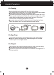
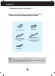
Accessories !!! Thank for selecting LGE products !!! Please make sure the following items are included with your monitor. If any items are missing, contact your dealer. Power Cord User's Guide/Cards 15-pin D-Sub Signal Cable (To set it up, this signal cable may be attached to this product before shipping out.) DVI-D Signal Cable (This feature is not available in all countries.) Audio Cable NOTE This accessories may look different from those shown here.
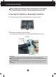
Connecting the Display Before setting up the monitor, ensure that the power to the monitor, the computer system, and other attached devices are turned off. Connecting the stand base or Removing the stand base 1. Place the monitor with its front facing downward on a cushion or soft cloth. 2. Assemble the Stand Base into the Stand Body. Be sure don't pull out the Stop Pin and make the Stand Base direction as shown.
Connecting the Display 3. Use a coin on the back of the stand base and turn the screw clockwise to tighten. 4. Lift and turn the monitor to face towards the front after the connection is made to the female part of the cable you're attaching. 5. When you desire to disintegrate the monitor from the stand base, use a coin to turn the screw counterclockwise. IMPORTANT This illustration depicts the general model of connection. Your monitor may differ from the items shown in the picture.
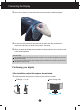
Connecting the Display Height Range : maximum 4.33 inches (110.0 mm) 110.0 mm * Please be sure to remove the Locking pin to adjust the height. When adjusting the angle of the screen, do not put your finger(s) in between the head of the monitor and the stand body. You can hurt your finger(s). When adjusting the height of the screen, do not put your finger(s) in between the head of the monitor and the stand base. You can hurt your finger(s).
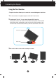
Connecting the Display Using the Pivot function -The pivot function allows you to rotate the screen 90 degrees clockwise. 1. Lift the monitor to its highest height to utilize the Pivot function. 2. Landscape & Portrait : You can rotate the panel 90 o clockwise. Please be cautious and avoid contact between the monitor head and the Stand Base when rotating the screen to access the Pivot function. If the monitor head touches the Stand Base, then the Stand Base could crack. Head section Stand section 3.
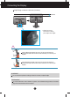
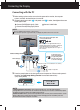
Connecting the Display Connecting with the PC 1. Before setting up the monitor, ensure that the power to the monitor, the computer system, and other attached devices is turned off. and power cord 2 in order, then tighten the screw of the signal cable. A Connect DVI-D(Digital signal) Cable C Connect Audio Cable B Connect D-sub(Analog signal) Cable 2. Connect signal input cable 1 NOTE This is a simplified representation of the rear view.
Control Panel Functions Front Panel Controls MENU Button OSD LOCKED/UNLOCKED This function allows you to lock the current control settings, so that they cannot be inadvertently changed. Press and hold the MENU button for several seconds. The message "OSD LOCKED" should appear. You can unlock the OSD controls at any time by pushing the MENU button for several seconds. The message "OSD UNLOCKED" should appear.
Control Panel Functions MODE Button Use this button to enter F-ENGINE, ORIGINAL RATIO(Only E2210PM),PHOTO EFFECT menus. For more information, refer to page 18. VOLUME Button To adjust the volume of headphone/speaker. INPUT Button (SOURCE Hot key) EXIT Button When two input signals are connected, you can select the input signal (D-SUB/DVI) you want. When only one signal is connected, it is automatically detected. The default setting is D-Sub. Exit the OSD(On Screen Display).
On Screen Display (OSD) Control Adjustment Screen Adjustment Making adjustments to the image size, position and operating parameters of the display is quick and easy with the On Screen Display Control system. A short example is given below to familiarize you with the use of the controls. The following section is an outline of the available adjustments and selections you can make using the OSD.
On Screen Display(OSD) Selection and Adjustment The following table indicates all the On Screen Display control, adjustment, and setting menus.
On Screen Display(OSD) Selection and Adjustment You were introduced to the procedure of selecting and adjusting an item using the OSD system. Listed below are the icons, icon names, and icon descriptions of the all items shown on the Menu. Press the MENU Button, then the main menu of the OSD appears.
On Screen Display(OSD) Selection and Adjustment Main menu Sub menu Description BRIGHTNESS To adjust the brightness of the screen. CONTRAST To adjust the contrast of the screen. SHARPNESS To adjust the clearness of the screen. Exit : Exit : Decrease : Increase : Select another sub-menu : Restart to select sub-menu COLOR TEMP PRESET Exit : Exit : Decrease : Increase : Select another sub-menu USER : Restart to select sub-menu Select the screen color.
On Screen Display(OSD) Selection and Adjustment Main menu Sub menu Description HORIZONTAL To move image left and right. VERTICAL To move image up and down. CLOCK To minimize any vertical bars or stripes visible on the screen background. The horizontal screen size will also change. Exit : Exit : Decrease PHASE : Increase : Select another sub-menu : Restart to select sub-menu To adjust the focus of the display.
On Screen Display(OSD) Selection and Adjustment Main menu Sub menu Description LANGUAGE To choose the language in which the control names are displayed. POWER INDICATOR Use this function to set the power indicator on the front side of the monitor to ON or OFF. If you set OFF, it will go off. If you set ON at any time, the power indicator will automatically be turned on.
On Screen Display(OSD) Selection and Adjustment You were introduced to the procedure of selecting and adjusting an item using the OSD system. Listed below are the icons, icon names, and icon descriptions of the all items shown on the Menu. Press the MODE Button, then the main menu of the OSD appears. Menu Name E1910PM Icons Submenus Icons E2210PM Submenus Button Tip Exit Move Select another sub-menu NOTE OSD (On Screen Display) menu languages on the monitor may differ from the manual.
On Screen Display(OSD) Selection and Adjustment Main menu Sub menu Description When F-ENGINE is not NORMAL,CONTRAST can not be selected. E1910PM NORMAL Select this when you want to use the product in the most general using environment. MOVIE Select this when you are watching a video or movie. E2210PM E1910PM E2210PM E1910PM INTERNET Select this when you are working on the document (Word etc.
On Screen Display(OSD) Selection and Adjustment (Only E2210PM) Main menu Sub menu WIDE Description Switch to full screen mode according to input image signal. ORIGINAL Change the input image signal ratio to original. * This function works only if input resolution is lower than monitor ratio (16:10).
On Screen Display(OSD) Selection and Adjustment Main menu Sub menu Description When PHOTO EFFECT is not NORMAL,CONTRAST can not be selected and COLOR is grey.When COLOR is selected down, PHOTO EFFECT is back to NORMAL and CONTRAST can be selected now. PHOTO EFFECT and F-ENGINE should not be unnormal at the same time. E1910PM NORMAL The Photo Effect function is disabled. E2210PM E1910PM GAUSSIAN This menu changes the screen to be more colorful and smoother.
On Screen Display(OSD) Selection and Adjustment Main menu Sub menu Description E1910PM SEPIA This menu changes the screen to be Sepia tone (brown color). E2210PM E1910PM MONOCH This menu changed the screen to be -ROME Gray tone(black-and-white Picture) .
Troubleshooting Check the following before calling for service. No image appears ● Is the power cord of the • Check and see if the power cord is connected properly to the power outlet. display connected? ● Is the power indicator light on? • Press the Power button. ● Is the power indicator flickering? • If the display is in power saving mode, try moving the mouse or pressing any key on the keyboard to bring up the screen. • Try to turn on the PC.
Troubleshooting Display image is incorrect ● Display Position is incorrect. • Press the AUTO button to automatically adjust your display image to the ideal setting. If the results are unsatisfactory, adjust the image position using the H position and V position icon in the on screen display. ● On the screen background, vertical bars or stripes are visible. • Press the AUTO button to automatically adjust your display image to the ideal setting.
Troubleshooting Display image is incorrect ● The screen color is mono or abnormal. • Check if the signal cable is properly connected and use a screwdriver to fasten if necessary. • Make sure the video card is properly inserted in the slot. • Set the color setting higher than 24 bits (true color) at Control Panel - Settings. ● The screen blinks. • Check if the screen is set to interlace mode and if yes, change it to the recommend resolution.
Specifications E1910PM Display 48.2 cm (19 inch) Flat Panel Active matrix-TFT LCD Anti-Glare coating Visible diagonal size : 48.2 cm 0.294 x 0.294 mm (Pixel pitch) Sync Input Horizontal Freq. Vertical Freq. Input Form 30 kHz to 83 kHz (Automatic) 56 Hz to 75 Hz (Automatic) Separate Sync. Digital Video Input Signal Input Input Form 15 pin D-Sub Connector DVI-D Connector (Digital) RGB Analog (0.
Specifications E2210PM Display 55.8 cm (22 inch) Flat Panel Active matrix-TFT LCD Anti-Glare coating Visible diagonal size : 55.8 cm 0.282 x 0.282 mm (Pixel pitch) Sync Input Horizontal Freq. Vertical Freq. Input Form 30 kHz to 83 kHz (Automatic) 56 Hz to 75 Hz (Automatic) Separate Sync. Digital Video Input Signal Input Input Form 15 pin D-Sub Connector DVI-D Connector (Digital) RGB Analog (0.
Specifications Preset Modes (Resolution) E1910PM Display Modes (Resolution) 1 2 3 4 5 6 7 8 *9 10 Horizontal Freq. (kHz) 31.468 31.469 37.500 37.879 46.875 48.363 60.123 67.500 63.981 79.976 720 x 400 640 x 480 640 x 480 800 x 600 800 x 600 1024 x 768 1024 x 768 1152 x 864 1280 x 1024 1280 x 1024 Vertical Freq. (Hz) 70 60 75 60 75 60 75 75 60 75 *Recommend Mode E2210PM Display Modes (Resolution) 1 2 3 4 5 6 7 8 9 10 *11 Horizontal Freq. (kHz) 31.468 31.469 37.500 37.879 46.875 48.363 60.123 67.
Installing the Wall mount plate This monitor satisfies the specifications of the Wall mount plate or the interchange device. 1. After moving the product to face downward, make sure to place it on a soft cloth or a cushion to avoid surface damage. 2. Separate the head and the stand with the use of a screwdriver.
Installing the Wall mount plate 3. Install the Wall mount plate. Wall mount plate(Separate purchase) This is stand-type or wall mount type and is connectable with Wall mount plate. Please refer to the installation guide for more details, which is provided when Wall mount plate is purchased. Wall Mount pad Kensington Security Slot Connected to a locking cable that can be purchased separately at most computer stores. Hole spacing : 75 mm x 75 mm.
Make sure to read the Safety Precautions before using the product. Keep the OWNER’S MANUAL(CD) in an accessible place for furture reference. The model and serial number of the SET is located on the back or one side of the SET. Record it below should you ever need service. MODEL SERIAL ENERGY STAR is a set of power-saving guidelines issued by the U.S.Environmental Protection Agency(EPA). As an ENERGY STAR Partner LGE U. S. A.,Inc.