User’s Guide L226WU Make sure to read the Important Precautions before using the product. Keep the User's Guide(CD) in an accessible place for future reference. See the label attached on the product and give the information to your dealer when you ask for service.
Important Precautions This unit has been engineered and manufactured to ensure your personal safety, however improper use may result in potential electrical shock or fire hazards. In order to allow the proper operation of all safeguards incorporated in this display, observe the following basic rules for its installation, use, and servicing. On Safety Use only the power cord supplied with the unit.
Important Precaautions On Installation Do not allow anything to rest upon or roll over the power cord, and do not place the display where the power cord is subject to damage. Do not use this display near water such as near a bathtub, washbowl, kitchen sink, laundry tub, in a wet basement, or near a swimming pool. Displays are provided with ventilation openings in the cabinet to allow the release of heat generated during operation.
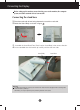
Connecting the Display Before setting up the monitor, ensure that the power to the monitor, the computer system, and other attached devices is turned off. Connecting the stand base 1. Place the monitor with its front facing downward on a cushion or soft cloth. 2. Rotate the Stand Body as shown in figure 1 . 1 3. Assemble the Stand Base(Front, Rear) into the Stand Body in the correct direction. 4.
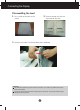
Connecting the Display Disassembling the stand 1. Put a cushion or soft cloth on aflat 2. Place the monitor face Down on surface. the cushion or soft cloth. 3. Pushing Latch inside, Take the stand base from stand body. Important This illustration depicts the general model of connection. Your monitor may differ from the items shown in the picture. Do not carry the product upside down holding only the stand base. The product may fall and get damaged or injure your foot.
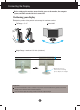
Connecting the Display Before setting up the monitor, ensure that the power to the monitor, the computer system, and other attached devices is turned off. Positioning your display 1. Adjust the position of the panel in various ways for maximum comfort. Tilt Range : -3˚~17˚ Swivel :356˚ Height Range : maximum 5 .51 inch (140.0mm) 140.0mm * Please be sure to remove the Locking pin to adjust the height.
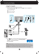
Connecting the Display Using the Computer 1. Make sure to turn off the computer and product. Connect signal input cable 1 and power cable 2 in order, then tighten the screw of the signal cable. A Connect DVI Cable B Connect D-sub Cable C Connect USB Cable USB Analog signal Digital signal DVI D-sub Power Cord D-SUB AC-IN DVI-D Wall-outlet type PC-outlet type C B DVI-D(This feature is not available in all countries.) A 2. Press button on the front switch panel to turn the power on.
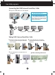
Use USB programs Connecting the USB(Universal Serial Bus) Cable 1. Plug in the USB cable as in the diagram. One USB Upstream port Two USB Downstream ports AC-IN D-SUB DVI-D Connect to downstream connectors of desktop or laptop computers, mouse, memory stick or USB hard disk. (However, the computer must support USB and have the USB port.) Tidying USB (Universal Serial Bus) Cable 1. Elevate the monitor as far as possible follow 2.
Use USB programs Use USB programs The display feature can be used by easily connecting the USB cable between laptops/desktops and the USB port at the back of the monitor. System Requirements In order to make full use of USB Display features, your computer must meet the following minimum system requirements: • 1.2 GHz CPU or higher, 512 MB memory or higher (Recommended Specifications: 1.6 GHz Core2 Duo CPU, 1 GB memory) • USB 2.
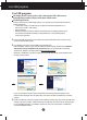
Use USB programs 4. When the installation of "LG USB Easy Connection" program is completed, icons as shown in the picture will be created in the taskbar. With these icons, you can easily use features such as Screen Resolution, Color Quality, Screen Rotation, Extend To, Extend and Mirror. ■ Screen Resolution : Provides information on the resolution that the USB supports. ■ Color Quality : You can choose 16 bit or 32 bit colors. ■ Screen Rotation : You can set the direction to display USB images.
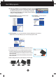
Use USB programs ■ Extend To : Sets the location to display USB images. (1: Standard monitor, 3: USB Monitor) Right Left Above Below ■ Extend : Expands the display to a sub screen. ■ Mirror : Shows the same display as the main screen. ■ Off : Does not to display data to make sure USB screen is not displayed. 5. When using multiple USB monitors, you can set "LG USB Easy Connection" program separately for each monitor. 1 In case of USB dual monitors. 2 Select No.
Control Panel Functions Front Panel Controls 6 SOURCE Button You can select the computer that you want to use by selecting input signal (DVI, D-Sub or USB). The default input signal is analogue (D-Sub). MENU Button Use this button to enter or exit the On Screen Display. OSD LOCKED/UNLOCKED This function allows you to lock the current control settings, so that they cannot be inadvertently changed. Press and hold the MENU button for several seconds. The message "OSD LOCKED" should appear.
Control Panel Functions - + Buttons Use these buttons to select or adjust functions in the On Screen Display. For more information, refer to page A19. AUTO/SET Button Use this button to enter a selection in the On Screen Display. AUTO IMAGE ADJUSTMENT When adjusting your display settings, always press the AUTO/SET button before entering the On Screen Display(OSD). This will automatically adjust your display image to the ideal settings for the current screen resolution size (display mode).
On Screen Display (OSD) Control Adjustment Screen Adjustment Making adjustments to the image size, position and operating parameters of the display is quick and easy with the On Screen Display Control system. A short example is given below to familiarize you with the use of the controls. The following section is an outline of the available adjustments and selections you can make using the OSD. NOTE Allow the display to stabilize for at least 30 minutes before making image adjustments.
On Screen Display(OSD) Selection and Adjustment The following table indicates all the On Screen Display control, adjustment, and setting menus.
On Screen Display(OSD) Selection and Adjustment You were introduced to the procedure of selecting and adjusting an item using the OSD system. Listed below are the icons, icon names, and icon descriptions of the all items shown on the Menu. Press the MENU Button, then the main menu of the OSD appears.
On Screen Display(OSD) Selection and Adjustment Main menu Sub menu Description PICTURE PICTURE BRIGHTNESS To adjust the brightness of the screen. CONTRAST To adjust the contrast of the screen. GAMMA Set your own gamma value. : -50/0/50 On the monitor, high gamma values display whitish images and low gamma values display high contrast images.
On Screen Display(OSD) Selection and Adjustment Main menu Sub menu Description POSITION POSITION HORIZONTAL To move image left and right. VERTICAL To move image up and down. MENU : Exit - : Decrease + : Increase SET : Select another sub-menu TRACKING TRACKING CLOCK To minimize any vertical bars or stripes visible on the screen background. The horizontal screen size will also change. PHASE To adjust the focus of the display.
On Screen Display(OSD) Selection and Adjustment Main menu Sub menu Description LANGUAGE To choose the language in which the control names are displayed. OSD POSITION To adjust position of the OSD window on the screen. WHITE BALANCE If the output of the video card is different the required specifications, the color level may deteriorate due to video signal distortion.
On Screen Display(OSD) Selection and Adjustment The OSD screen will appear when you touch the button on the front of the monitor. Menu Name Icons Sub-menu Name FLATRON F-ENGINE Screen when applied Screen when not applied When you execute F-ENGINE, two tones will appear on the screen as shown. The applied screen will appear on the left side, whereas the non-applied screen will appear on the right side.Touch the SET button to use the adjusted screen.
Troubleshooting Check the following before calling for service. No image appears ● Is the power cord of the • Check and see if the power cord is connected properly to the power outlet. display connected? ● Is the power on and the • Adjust the brightness and the contrast. power indicator blue or green? ● Is the power indicator amber? • If the display is in power saving mode, try moving the mouse or pressing any key on the keyboard to bring up the screen. • Try to turn on the PC.
Troubleshooting Display image is incorrect ● Display Position is incorrect. • Press the AUTO/SET button to automatically adjust your display image to the ideal setting. If the results are unsatisfactory, adjust the image position using the H position and V position icon in the on screen display. ● On the screen background, vertical bars or stripes are visible. • Press the AUTO/SET button to automatically adjust your display image to the ideal setting.
Troubleshooting Display image is incorrect ● The screen color is mono or abnormal. • Check if the signal cable is properly connected and use a screwdriver to fasten if necessary. • Make sure the video card is properly inserted in the slot. • Set the color setting higher than 24 bits (true color) at Control Panel - Settings. ● The screen blinks. • Check if the screen is set to interlace mode and if yes, change it to the recommend resolution.
Specifications Display 22 inches (55.868 cm) Flat Panel Active matrix-TFT LCD Anti-Glare coating 22 inches viewable 0.282*0.282 mm pixel pitch Sync Input Horizontal Freq. Vertical Freq. Input Form Video Input Signal Input Input Form Resolution 15 pin D-Sub Connector DVI-D Connector (Digital) USB Connector (Digital) RGB Analog (0.
Specifications Stand Base Attached ( Power cord Wall-outlet type or PC-outlet type USB Standard USB 2.0, Self-Power Data Rate Max 480 Mbps ), Detached ( O ) Power Consumption Max 2.5W x 2 NOTE Information in this document is subject to change without notice.
Specifications Preset Modes (Resolution) Analog,Digital supporting modes Display Modes (Resolution) 1 2 3 4 5 6 7 8 9 10 11 *12 Horizontal Freq. (kHz) 720 x 400 640 x 480 640 x 480 800 x 600 800 x 600 1024 x 768 1024 x 768 1152 x 864 1280 x 1024 1280 x 1024 1680 x 1050 1680 x 1050 31.468 31.469 37.500 37.879 46.875 48.363 60.123 67.500 63.981 79.976 64.674 65.290 Vertical Freq.
Installing the Wall mount plate This monitor satisfies the specifications of the Wall mount plate or the interchange device. 1. Place the monitor with its front facing downward on a soft cloth. 2. Separate the stand using a screwdriver as shown in the picture. 3. Install the Wall mount plate. Wall mount plate(Separate purchase) This is stand-type or wall mount type and is connectable with Wall mount plate.
Digitally yours