ENGLISH OWNER’S MANUAL MONITOR TV Please read this manual carefully before operating your set and retain it for future reference. MONITOR TV MODELS M1962D M2062D M2262D M2362D M2762D www.lge.
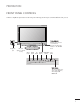
PREPARATION FRONT PANEL CONTROLS ■ This is a simplified representation of the front panel. The image shown may be somewhat different from your set. Headphone Jack IR receiver (Remote controller receiver) Power Indicator illuminates blue when the set is switched on. Note:You can adjust Power indicator in the OPTION menu.
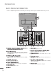
PREPARATION BACK PANEL INFORMATION ■ This is a simplified representation of the back panel. The image shown may be somewhat different from your set. 1 3 2 3 4 AUDIO IN (RGB/DVI) 5 6 COMPONENT IN OPTICAL DIGITAL AUDIO OUT Y AV V1 AV 1 VIDEO PR DVI-D IN (PC) AC IN PCMCIA (Personal Computer Memory Card International Association) Card Slot This feature is not available in all countries. 2 Power Cord Socket This set operates on AC power. The voltage is indicated on the Specifications page.
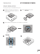
PREPARATION STAND INSTALLATION ■ The image shown may be somewhat different from your set. 1 Carefully place the product screen side down on a cushioned surface that will protect product and screen from damage. 3 Turn the Stand Base Lock through 90° to fix the Stand Base to the Stand Body.
EXTERNAL EQUIPMENT SETUP ■ To prevent the equipment damage, never plug in any power cords until you have finished connecting all equipment. ■ The image shown may be somewhat different from your set. HD RECEIVER SETUP When connecting with a component cable 14 1 Connect the SET-TOP outputs to the C O M P O N E N T I N V I D E O sockets (Y PB PR) on the set. 2 Connect the audio cable from the SET-TOP to C O M P O N E N T I N A U D I O sockets of the set.
EXTERNAL EQUIPMENT SETUP 1 Connect the HDMI output of the digital set-top box to the H D M I I N jack on the set. HDMI IN 2 When connecting with a HDMI HDMI IN 1 or 1 Connect the digital set-top box to H D M I I N jack on the set. 1 2 Connect the audio output of the digital set-top box to the A U D I O I N ( R G B / D V I ) jack on the set. 3 Turn on the digital set-top box. (Refer to the owner’s manual for the digital set-top box.
EXTERNAL EQUIPMENT SETUP DVD SETUP When connecting with a component cable 1 Connect the video output sockets (Y PB PR) of the DVD to the C O M P O N E N T I N V I D E O sockets (Y PB PR) of the set. 2 Connect the audio cable from the DVD to C O M P O N E N T I N A U D I O sockets of the set. 3 Press the I N P U T button to select C o m p o n e n t. 4 Press the P L A Y button on the DVD. The DVD playback picture appears on the screen.
EXTERNAL EQUIPMENT SETUP When connecting with a Euro Scart[DVD] 1 AV 1 AV 2 Connect the Euro scart socket of the DVD to the Euro scart socket of the set. 2 Press the I N P U T button to select A V 1. If connected to A V 2 Euro scart socket, select A V 2 input source. 3 Press the P L A Y button on the DVD. The DVD playback picture appears on the screen. 1 (R) (L) AUDIO/ VIDEO AUDIO ! NOTE G G Signal type RGB, i.e.
EXTERNAL EQUIPMENT SETUP VCR SETUP To avoid picture noise (interference), leave an adequate distance between the VCR and set. ■ Typically a still picture is shown on the VCR. If a user uses 4:3 picture format for a long time, an afterimage may remain on the sides of the screen. ■ When connecting with an antenna ANTENNA/ CABLE IN ANT OUT S-VIDEO ANT IN OUTPUT SWITCH VIDEO L 1 Wall Jack 2 Antenna 1 Connect the RF out socket of the VCR to the aerial socket of the set.
AV 1 AV 2 EXTERNAL EQUIPMENT SETUP When connecting with a RCA cable 1 R AV 2 ANT IN ANT OUT AV 1 L 3 Press the PLAY button on the VCR. The VCR playback picture appears on the screen. S-VIDEO VIDEO Press the INPUT button to select AV3. AUDIO R 2 AV-IN 3 (MONO) L Connect the audio/video out sockets of the VCR to AUDIO/VIDEO in sockets of the set. VIDEO 1 ! NOTE G If you have a mono VCR, connect the audio cable from the VCR to the AUDIO L/MONO jack of the set.
EXTERNAL EQUIPMENT SETUP When connecting with a Euro Scart[VCR] Connect the Euro scart socket of the VCR to the Euro scart socket of the set. 1 AV V1 Press the P L A Y button on the VCR. If your VCR outputs an AV switching signal via the Scart lead, the set will auto switch to A V 1 mode on start of playback, but if you want to keep on watching in TV mode, press the D / E or NUMBER buttons. If connected to A V 2 Euro scart socket, select A V 2 input source.
EXTERNAL EQUIPMENT SETUP PC SETUP This product provides Plug and Play capability, meaning that the PC adjusts automatically to the set's settings. When connecting with a D-sub 15 pin cable Connect the signal cable from the monitor output socket of the PERSONAL COMPUTER to the PC input socket of the set. 1 RGB IN (PC) 2 Connect the audio cable from the PC to the A U D I O I N ( R G B / D V I ) sockets of the set. 3 Press the INPUT button to select R G B.
EXTERNAL EQUIPMENT SETUP When connecting with a DVI cable 1 Connect the DVI output of the PC to the D V I - D I N jack on the set. 2 Connect the audio cable from the PC to the A U D I O I N ( R G B / D V I ) sockets of the set. AUDIO IN (RGB/DVI) DVI-D IN (PC) 1 DVI OUTPUT 2 AUDIO ! NOTE G If the set is cold, there may be a small “flicker” when the set is switched on. This is normal, there is nothing wrong with the set.
EXTERNAL EQUIPMENT SETUP BACK COVER FOR WIRE ARRANGEMENT Tie cables together with a cable tie as shown in the illustration.
EXTERNAL EQUIPMENT SETUP RGB/DVI[PC] Resolution 640x480 800x600 1024x768 1280x768 1280x800 1360x768 Horizontal Frequency(kHz) Vertical Frequency(Hz) 31.469 37.5 37.879 46.875 48.363 60.123 47.776 49.306 47.712 47.7 60 75 60 75 60 75 60 60 60 60 Resolution 720x350 720x400 640x480 800x600 832x624 1024x768 1152x870 1280x1024 1280x1024 1600x900 Horizontal Frequency(kHz) 25.175 31.468 31.469 37.5 37.879 46.875 49.725 48.363 60.123 68.681 63.981 79.
WATCHING TV /PROGRAMME CONTROL REMOTE CONTROL KEY FUNCTIONS When using the remote control, aim it at the remote control sensor on the set. A TYPE 1 TV/PC POWER TV/RADIO TEXT I/II MUTE 1 2 3 4 5 6 7 8 9 LIST 0 Q.VIEW 1 TV/PC Selects TV or PC mode. 2 INPUT External input mode rotates in regular sequence. 2 MENU 3 OK TV/RADIO Selects Radio or TV channel. I/II Selects the sound output.(Refer to the p.73~74) MUTE Switches the sound on or off. EXIT 3 4 0~9 number Selects a programme.
WATCHING TV /PROGRAMME CONTROL A TYPE TV/PC POWER TV/RADIO TEXT I/II INPUT MUTE 1 TELETEXT These buttons are used for teletext. BUTTONS For further details, see the ‘Teletext’ section. (Refer to the p.100~102) 1 1 2 3 4 5 6 7 8 9 LIST 0 Q.VIEW MENU 2 USB Menu Controls USB menu (Photo List and Music List) control buttons (Refer to the p.92) EXIT 3 Q.MENU Select the desired quick menu source. (Refer to the p.29) OK MARK Check and un-check programmes in the recorded set menu.
WATCHING TV /PROGRAMME CONTROL TURNING ON THE TV - When your TV is turned on, you will be able to use its features. 1 Firstly,connect the power cord correctly and check the main power( r / I )on the TV. 2 Set ID : Off In standby mode to turn TV on, press the INPUT or PR D / E button on the TV or press the POWER button on the remote control and the TV will switch on.
WATCHING TV /PROGRAMME CONTROL PROGRAMME SELECTION 1 Press the P R + or - or NUMBER buttons to select a programme number. VOLUME ADJUSTMENT 1 A TYPE TV/PC POWER TV/RADIO TEXT I/II INPUT MUTE 1 2 3 4 5 6 7 8 9 LIST 0 Q.VIEW MENU EXIT Press the VOL + or - button to adjust the volume. OK If you want to switch the sound off, press the MUTE button. You can cancel this function by pressing the MUTE, VOL + or - , or I/II button. GUIDE INFO i RETURN * VOL PR FAV Q.MENU T.
WATCHING TV /PROGRAMME CONTROL QUICK MENU Your TV's OSD (On Screen Display) may differ slightly from that shown in this manual. Q.Menu (Quick Menu) is a menu of features which users might use frequently. • A s p e c t R a t i o: Selects your desired picture format. For Zoom Setting, select 14:9, Zoom and Cinema Zoom in Ratio Menu. After completing Zoom Setting, the display goes back to Q.Menu. • P i c t u r e M o d e : Selects your desired Picture Mode.
WATCHING TV /PROGRAMME CONTROL ON SCREEN MENUS SELECTION AND ADJUSTMENT Your set's OSD (On Screen Display) may differ slightly from what is shown in this manual.
WATCHING TV /PROGRAMME CONTROL AUTO PROGRAMME TUNING Use this to automatically find and store all available programmes. When you start auto programming in digital mode, all previously stored service information will be deleted. The maximum number of programmes that can be stored is 500. But the number may differ slightly depending on broadcasting signals.
WATCHING TV /PROGRAMME CONTROL MANUAL PROGRAMME TUNING (IN DIGITAL MODE) Manual Tuning lets you manually add a programme to your programme list. SETUP Move SETUP OK Auto tuning Manual M a n u atuning l tuning Programme Edit Software Update : On Diagnostics CI Information Move Auto tuning Manual M a n u atuning l tuning Programme Edit Software Update : On Diagnostics CI Information OK F DTV G Your receiver will add this channel to your channel list. UHF CH.
WATCHING TV /PROGRAMME CONTROL MANUAL PROGRAMME TUNING (IN ANALOGUE MODE) Manual Tuning lets you manually tune and arrange the stations in whatever order you desire.
WATCHING TV /PROGRAMME CONTROL A Assigning a station name You can assign a station name with five characters to each programme number. 1MENU 5 Select SETUP. OK 2 OK Select Manual Tuning. Select the position and make your choice of the second character, and so on. You can use the alphabet A to Z , the number 0 to 9 , +/ -, and space. 6 3 OK OK Select Close. OK Select Store. Select TV. 7 4 Select Name. • Press the MENU or EXIT button to close the menu window.
WATCHING TV /PROGRAMME CONTROL PROGRAMME EDIT When a programme number is skipped, it means that you will be unable to select it using PR + / - button during TV viewing. If you wish to select the skipped programme, directly enter the programme number with the NUMBER buttons or select it in the Programme edit menu This function enables you to skip the stored programmes. In some countries, it is possible to move a programme number by using the YELLOW button only.
WATCHING TV /PROGRAMME CONTROL IN DTV/RADIO MODE A Skipping a programme number 1 Select a programme number to be skipped. 2 BLUE Turn the skipped programme number to blue. 3 BLUE A that you will be unable to select it using the PR + / - button during normal TV viewing. • If you wish to select a skipped programme, directly enter the programme number with the NUMBER buttons or select it in the programme edit or EPG. Release the skipped programme.
WATCHING TV /PROGRAMME CONTROL IN TV MODE This function enables you to delete or skip the stored programmes. You can also move some channels to other programme numbers. A Auto Sort 1 GREEN Start Auto Sort. • After activating Auto Sort once, you can no longer edit programmes. Deleting a programme A 1 Select a programme number to be deleted. • The selected programme is deleted, all the fol- lowing programmes are shifted up one 2 RED Turn the deleted programme number to red.
WATCHING TV /PROGRAMME CONTROL SOFTWARE UPDATE Software Update means software can be downloaded through the digital terrestrial broadcasting system. SETUP Move SETUP OK Move Auto tuning Manual tuning Programme Edit S o f t w a rUpdate e U p d a: tOn e : On Software Auto tuning Manual tuning Programme Edit S o f t w a rUpdate e U p d a: tOn e : OO n ff Software Diagnostics CI Information Diagnostics CI Information 3 1MENU Select S E T U P. Select S o f t w a r e U p d a t e.
WATCHING TV /PROGRAMME CONTROL DIAGNOSTICS (IN DIGITAL MODE ONLY) This function enables you to view information on the Manufacturer, Model/Type, Serial Number and Software Version. This displays the information and signal strength of the tuned MUX. This displays the signal information and service name of the selected MUX. (*MUX: A higher directory of channels in digital broadcasting (a single MUX contains multiple channels.)) SETUP Move Engineering Diagnostics OK Manufacturer Model/Type Serial No.
WATCHING TV /PROGRAMME CONTROL CI [COMMON INTERFACE] INFORMATION This function enables you to watch some encrypted services (paid services). If you remove the CI Module, you cannot watch paid services. When the module is inserted into the CI slot, you can access the module menu. To purchase a module and smart card, contact your dealer. Do not repeatedly insert or remove a CAM module from the set. This may cause a malfunction.
WATCHING TV /PROGRAMME CONTROL SELECTING THE PROGRAMME TABLE You can check which programmes are stored in the memory by displaying the programme table. Displayed in the Locked Programme. A Displaying programme LIST • You may find some blue programmes. These 1 Display the PROGRAMME LIST. LIST A Selecting a programme in the programme list 1 From the programme you are currently watching, the mode will change from TV to DTV to Radio. Switch to the chosen programme number.
EPG (ELECTRONIC PROGRAMME GUIDE) (IN DIGITAL MODE) This system has an Electronic Programme Guide (EPG) to help navigate through all the possible viewing options. The EPG supplies information such as programme listings, start and end times for all available services. In addition, detailed information about the programme is often available in the EPG (the availability and amount of these programme details will vary, depending on the particular broadcaster).
EPG (ELECTRONIC PROGRAMME GUIDE) (IN DIGITAL MODE) Button Function in NOW/NEXT Guide Mode RED Change EPG mode. Programme Guide 1 YLE TV1 BLUE Enter Timer Record/Remind setting mode. Enter Timer Record/Remind list mode. 6/ Mar 2006 15:09 E YELLO YELLOW ALL NOW 1 YLE TV1 NEXT Keno World Business Fantomen Kritiskt ABC That ’70s show 2 YLE TV2 Your World Today 4 TV.. Legenen om Den....
EPG (ELECTRONIC PROGRAMME GUIDE) (IN DIGITAL MODE) Button Function in Date Change Mode GREEN Switch off Date setting mode. Programme Guide 1 YLE TV1 Change to the selected date. ALL 6/Mar(Mon) 14:00 1 YLE TV1 2 YLE TV2 4 TV.. Select a date. 5 YLE FST 6 CNN 8 YLE24 6/ Mar 2006 15:09 E OK ... 15:00 Kungskonsumente No Information No Information TV2: Farmen No Information No Information No Information No Information ... ... ... Tänään otsikoissa E Date. Change Switch off Date setting mode.
EPG (ELECTRONIC PROGRAMME GUIDE) (IN DIGITAL MODE) Button Function in Record/Remind Setting Mode - This function is available only when recording equipment that uses 8 pin recording signalling has been connected to the DTV-OUT terminal, using a SCART cable. YELLO YELLOW Change to Guide or Timer list mode. Schedule 6/ Mar 2006 15:09 Type Programme Record 6CNN Date Start Time End Time 17 : 00 17 : 30 E OK Save Timer Record/Remind. 10 Mar.
PICTURE CONTROL PICTURE SIZE (ASPECT RATIO) CONTROL 16:9, Just Scan, Original, 4:3, 14:9, Zoom, Cinema Zoom and Full Wide. If a fixed image is displayed on the screen for a long time, that fixed image may become imprinted on the screen and remain visible. You can adjust the enlarge proportion using D E button. This function works in the following signal. 1Q. MENU • You can also adjust Aspect Ratio in the Select A s p e c t R a t i o. 2 OK Select the desired picture format.
PICTURE CONTROL • Original When your TV receives a wide screen signal, it will automatically change to the picture format broadcast. • Cinema Zoom Choose Cinema Zoom when you wish the picture to be altered, both horizontally extended and vertically cropped. The picture adopting a compromise between alteration and screen coverage. Original • 14:9 You can view a picture format of 14:9 or a general TV programme in the 14:9 mode.
PICTURE CONTROL AUTO BRIGHT When ON is selected, this function adjusts the screen brightness automatically, depending on the surrounding environment, to provide optimal viewing conditions. When OFF is selected, this function is turned off.
TO USE A USB DEVICE ■ If you don't press any button for a while during the playing, the play information box (as shown in the below) will float as a screen saver. ■ The ‘Screen Saver’? Screen saver is to prevent screen pixel damage due to an fixed image remaining on the screen for a extended period of time. ! NOTE When music is playing, is displayed in back of the music title. A damaged or corrupted music does not play but displays 00:00 in playtime.
TELETEXT This feature is not available in all countries. Teletext is a free service broadcast by most TV stations which gives up-to-the-minute information on news, weather, television programmes, share prices and many other topics. The teletext decoder of this set can support the SIMPLE, TOP and FASTEXT systems. SIMPLE (standard teletext) consists of a number of pages which are selected by directly entering the corresponding page number.
TELETEXT FASTEXT The teletext pages are colour coded along the bottom of the screen and are selected by pressing the corresponding coloured button. A Page selection 1 2 3 4 Press the T . O P T button and then use D E button to select i menu. Display the index page. You can select the pages which are colour coded along the bottom line with corresponding coloured buttons. AS with SIMPLE teletext mode, you can select a page by entering its three digit page number with the NUMBER buttons in FASTEXT mode.
DIGITAL TELETEXT *This function works in UK/Ireland only. The set gives you access to a digital teletext which is greatly improved in various aspects such as text, graphics and so on. This digital teletext can be accessed by special digital teletext services and specific services which broadcast digital teletext. You should select off from the subtitle language to display teletext by pressing SUBTITLE button.
APPENDIX TROUBLESHOOTING The operation does not work normally. Check to see if there is any object between the product and the remote control causing obstruction. Ensure you are pointing the remote control directly at the set. A Ensure that the batteries are installed with correct polarity (+ to +, - to -). A Ensure that the correct remote operating mode is set: TV, VCR, etc. A Install new batteries.
APPENDIX The audio function does not work. A Picture OK & No sound A A A No output from one of the speakers Unusual sound from inside the product Press the VOL + or - button. Sound muted? Press MUTE button. Try another channel. The problem may be with the broadcast. Are the audio cables installed properly? A Adjust B a l a n c e in menu option.
APPENDIX ‘Unknown Product’ message appears when the product is connected. A Install the product driver, which is provided with the product, or download it from the web site. (http://www.lge.com) A See if the plug_&_play function is supported by referring to the video card user’s guide. Did you install the driver? After-image appears on the product. After-image appears when the product is turned off. A If you use a fixed image for a long time, the pixels may be damaged quickly.
APPENDIX MAINTENANCE Early malfunctions can be prevented. Careful and regular cleaning can extend the amount of time you can enjoy your new set. Caution: Be sure to turn the power off and unplug the power cord before you begin any cleaning. Cleaning the Screen 1 To keep the dust off your screen for a while, wet a soft cloth in a mixture of lukewarm water and a little fabric softener or dishwashing detergent. Wring the cloth until it’s almost dry, and then use it to wipe the screen.
APPENDIX PRODUCT SPECIFICATIONS LCD Panel Video Signal Screen Type 470.1mm Wide (18.51 inch) TFT (Thin Film Transistor) LCD (Liquid Crystal Display) Panel Visible diagonal size: 470.1mm Pixel Pitch 0.30(H) mm x 0.30(V) mm Max.
APPENDIX PRODUCT SPECIFICATIONS LCD Panel Video Signal Screen Type 508.5 mm Wide (20.0 inch) TFT (Thin Film Transistor) LCD (Liquid Crystal Display) Panel Visible diagonal size : 508.5 mm Pixel Pitch 0.2766 (H) mm x 0.2766 (V) mm Max.
APPENDIX PRODUCT SPECIFICATIONS LCD Panel Video Signal Screen Type 546.86 mm Wide (21.53 inch) TFT (Thin Film Transistor) LCD (Liquid Crystal Display) Panel Visible diagonal size: 546.86 mm Pixel Pitch 0.248(H) mm x 0.248(V) mm Max.
APPENDIX PRODUCT SPECIFICATIONS LCD Panel Video Signal Screen Type 584.2 mm Wide (23 inch) TFT (Thin Film Transistor) LCD (Liquid Crystal Display) Panel Visible diagonal size : 584.2 mm Pixel Pitch 0.265(H) mm x 0.265(V) mm Max.
APPENDIX PRODUCT SPECIFICATIONS LCD Panel Video Signal Screen Type 686 mm Wide (27 inch) TFT (Thin Film Transistor) LCD (Liquid Crystal Display) Panel Visible diagonal size: 686 mm Pixel Pitch 0.3114(H) mm x 0.3114(V) mm Max.
APPENDIX PROGRAMMING THE REMOTE CONTROL The remote is a multi-brand or universal remote. It can be programmed to operate most remote-controllable devices of other manufacturers. Note that the remote may not control all models of other brands. Programming a code into a remote mode 1 Test your remote control.
APPENDIX VCR Brand AIWA AKAI Codes 034 016 125 AMPRO 072 ANAM 031 AUDIO DYNAMICS 012 BROKSONIC 035 CANON 028 CAPEHART 108 CRAIG 003 CURTIS MATHES 031 DAEWOO 005 065 112 DAYTRON 108 DBX 012 DYNATECH 034 ELECTROHOME 059 EMERSON 006 029 036 129 FISHER 003 FUNAI 034 GE 031 107 GO VIDEO 132 HARMAN KARDON HITACHI 004 043 INSTANTREPLAY 031 JCL 031 JCPENNY 012 040 JENSEN 043 JVC 012 048 130 KENWOOD 014 047 LG (GOLDSTAR) 001 101 LLOYD 034 LXI 003 017 MAGIN 040 Brand Codes Brand MAGNAVOX 031 067 012 069 101 02
APPENDIX IR CODES 1. How to Connect A Connect your wired remote control to the Remote Control port on the set. 2. Remote Control IR Codes A Output waveform Single pulse, modulated with 37.
APPENDIX Code (Hexa) 00 01 02 03 40 41 06 07 08 09 0B 10 11 12 13 14 15 16 17 18 19 1A 1E 20 21 28 39 43 44 45 50 F0 0A 5B 1E 53 61 63 71 72 AA AB Function PR + PR VOL + VOL Up (D) Down (E) Right (G) Left (F) POWER MUTE INPUT Number Key 0 Number Key 1 Number Key 2 Number Key 3 Number Key 4 Number Key 5 Number Key 6 Number Key 7 Number Key 8 Number Key 9 Q.VIEW FAV TEXT T.OPT RETURN SUBTITLE MENU OK( ) Q.
APPENDIX EXTERNAL CONTROL DEVICE SETUP RS-232C Setup Connect the RS-232C (serial port) input jack to an external control device (such as a computer or an A/V control system) to control the product’s functions externally. Connect the serial port of the control device to the RS232C jack on the product back panel. Note: RS-232C connection cables are not supplied with the product. RS-232C IN (CONTROL & SERVICE) Type of Connector; D-Sub 9-Pin Male No.
APPENDIX Set ID Use this function to specify a set ID number. Refer to ‘Real Data Mapping’. G p . 121 OPTION Move OPTION OK D Country : UK Country Input Label OK : UK Input Label Key Lock : Off Key Lock : Off Set ID : Off Set ID : Off Power Indicator F Power Indicator Off G Close DDC CI : On DDC CI : On Mode Setting : Home Use Mode Setting : Home Use Factory Reset 1MENU Move D Factory Reset Select O P T I O N. 2 OK Select S e t I D.
APPENDIX Communication Parameters Baud rate : 9600 bps (UART) A Data length : 8 bits A Parity : None Stop bit : 1 bit A Communication code : ASCII code A Use a crossed (reverse) cable. A A Command Reference List Transmission / Receiving Protocol COMMAND COMMAND DATA 1 2 (Hexadecimal) 01. Power 02. Aspect Ratio 03. Screen Mute 04. Volume Mute 05. Volume Control 06. Contrast 07. Brightness 08. Colour 09. Tint 10. Sharpness 11. OSD Select 12. Remote control lock mode 13. Treble 14. Bass 15. Balance 16.
APPENDIX 01. Power (Command: k a) 04. Volume Mute (Command: k e) G To control Power On/Off of the TV. G To control volume mute on/off. Transmission You can also adjust mute using the MUTE button on remote control. Transmission [k][a][ ][Set ID][ ][Data][Cr] Data 00 : Power Off Ack 01 : Power On [a][ ][Set ID][ ][OK/NG][Data][x] [k][e][ ][Set ID][ ][Data][Cr] Data 00 : Volume mute on (Volume off) 01 : Volume mute off (Volume on) Ack [e][ ][Set ID][ ][OK/NG][Data][x] 02.
APPENDIX 09. Tint (Command: k j) 13. Treble (Command: k r) G To adjust the screen tint. G To adjust treble. You can also adjust tint in the PICTURE menu. Transmission [k][j][ ][Set ID][ ][Data][Cr] Data Min : 00 ~ Max : 64 * Refer to ‘Real data mapping’. See page 121. Ack [j][ ][Set ID][ ][OK/NG][Data][x] 10. Sharpness (Command: k k) You can also adjust treble in the AUDIO menu. In case that SRS TruSurround HD is ‘On’, it doesn’t operate and is fixed to 50.
APPENDIX 17. Auto Configure (Command: j u) 20. Key (Command : m c) G To adjust picture position and minimize image shaking G To send IR remote key code. automatically. It works only in RGB (PC) mode. Transmission Transmission [j][u][ ][Set ID][ ][Data][Cr] Data 01: To set Ack [m][c][ ][Set ID][ ][Data][Cr] Data Key code - Refer to page 115. Ack [c][ ][Set ID][ ][OK/NG][Data][x] [u][ ][Set ID][ ][OK/NG][Data][x] * Real data mapping 00 : Step 0 A : Step 10 (Set ID 10) 21.
UK Only
Make sure to read the Safety Precautions before using the product. Keep the Owner’s Manual(CD) in an accessible place for furture reference. The model and serial number of the SET is located on the back and one side of the SET. Record it below should you ever need service.