OWNER’S MANUAL Video Conference Monitor Please read this manual carefully before operating your set and retain it for future reference. MODEL AVS2400 P/NO : COV30805901 1101(V1.
1 Safety Information Safety Information 1 Safety Information CAUTION RISK OF ELECTRIC SHOCK DO NOT OPEN CAUTION: TO REDUCE THE RISK OF ELECTRIC SHOCK DO NOT REMOVE COVER (OR BACK) NO USER-SERVICEABLE PARTS INSIDE REFER SERVICING TO QUALIFIED SERVICE PERSONNEL.
Safety Information European representative : LG Electronics Service Europe B.V. Veluwezoom 15, 1327 AE Almere. The Netherlands (Tel : +31-(0)36-547-8888) Disposal of your old appliance 1. When this crossed-out wheeled bin symbol is attached to a product it means the product is covered by the European Directive 2002/96/ EC. 2.
Safety Information On Safety 1 Safety Information This unit has been engineered and manufactured to ensure your personal safety, however improper use may result in potential electrical shock or fire hazards. In order to allow the proper operation of all safeguards incorporated in this display, observe the following basic rules for its installation, use, and servicing. Use only the power cord supplied with the unit.
Safety Information On Cleaning • • • • Unplug the display before cleaning the face of the display screen. Use a slightly damp (not wet) cloth. Do not use an aerosol directly on the display screen because over-spraying may cause electric shock. When cleaning the product, unplug the power cord and scrub gently with a soft cloth to prevent scratching. Do not clean with a wet cloth or spray water or other liquids directly onto the product. An electric shock may occur.
Contents Contents 1 Safety Information 3 IMPORTANT SAFETY INSTRUCTIONS 4 On Safety 4 On Installation 5 On Cleaning 5 On Repacking 5 On Disposal 5 Lifting and moving the VCS 2 Preparation 8 Introduction 8 Features 9 Unpacking 10 Overview 13 Attaching the stand 14 Disassembling the stand 14 Using the Kensington security system (optional) 15 Connecting to a PC 17 Connecting Network 17 Connecting Power 18 Connecting Headphones 18 Connecting a Microphone 19 Attaching
Contents 52 Saving and Restoring a System Configuration 63 Locking and Unlocking Entries in the REDIAL List 53 Copying Screen Text to the Clipboard 63 Removing an Entry from the REDIAL List 53 Downloading Call History 63 53 Upgrading System Software Adding a REDIAL List Entry to the Directory 54 54 Managing Calls from the Web Administration Interface Upgrading your System Software 54 Troubleshooting Upgrade Failures 55 Upgrade Error Codes 4 Operation 56 Near End Video Quality 56 Pl
Preparation 2 Preparation 2 Preparation Introduction The LG video conference monitor is designed to be used for video conferencing, enabling people in a different space such as a conference room or office to have a meeting (by seeing, listening and speaking to each other on a screen.
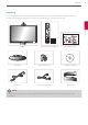
Preparation 9 Unpacking Check your product box for the following items. If there are any missing accessories, contact the local dealer where you purchased your product. The illustrations in this manual may differ from the actual product and item.
Preparation Overview Front of the VCS a bcd 2 Preparation ef a High Definition Camera. b Internal microphone. c VCS condition Indicator: Lights when the VCS turns on. d Remote Sensor: Point the remote control here. e : Logo for Headset jack. f : Logo for Microphone jack. g VCS/MNT: Changes the input source between VCS and Monitor. h OSD menu control buttons. g h i • MENU: Displays the MENU setup window or moves to the previous menu.
Preparation 11 NOTE OSD lock / unlock function You can lock the current control settings, so that they cannot be inadvertently changed. 1. Press and hold the MENU button for several seconds. The message “OSD LOCKED” should appear. 2. You can unlock the OSD controls at any time by holding the MENU button for several seconds. The message “OSD UNLOCKED” should appear. Monitor power button: Turns the monitor on and off. The camera and system power are not turned off by the monitor power button.
Preparation Remote Control This remote control provides wireless control of Video conference system functions and enables you to navigate the user interface, place and receive calls. (You cannot control the monitor using this remote control) Button 2 Description Button Description Preparation Use this button when the system receives a call or to manually make a call. Use this button to mute the microphones of the near end system. Use this button when you want to hang up.
Installation 13 3 Installation Connections CAUTION Attaching the stand 1. Lay the VCS with the screen side down on a flat surface. CAUTION Lay a foam mat or soft protective cloth on the surface and then lay the VCS carefully to prevent the camera from breaking and protect the screen from damage. 2. Make sure to assemble the front and rear side of the stand. Push it into the VCS body as shown in the following illustration. 3. Turn the Stand locking screw clockwise to tighten. Do not over tighten.
Installation CAUTION Do not attempt to tighten a screw too tightly. If you do, the thread groove or the grip of the locking nut may become damaged. Tighten a screw to fix a monitor on the stand base so that it does not separate. This may cause an accident. 4. Once assembled, lift the monitor up carefully and face the front side. CAUTION Do not make the monitor stand by holding the camera. It can be broken and damaged. 3 Installation Disassembling the stand 1.
Installation 15 Connecting to a PC This VCS supports the Plug & Play feature and has built-in speakers. Connect the VCS according to your PC. Refer to the following table. HDMI D-SUB Video O (Digital) O (Analog) Audio O (Digital) X HDMI connection Transmits the digital video and audio signals from your PC to the Monitor set. Connect the PC and the Monitor set with the HDMI cable as shown in the following illustrations.
Installation D-SUB connection Transmits the analog video signal from your PC to the Monitor set. Connect the PC and the Monitor set with the supplied D-sub 15 pin signal cable as shown in the following illustrations.
Installation 17 Connecting Network Connect the LAN port on the rear of the VCS to your network using the optional LAN cable. This device has two LAN ports. One of them is for network and the other is for PC. If you connect the PC as shown below, you can use the network on the PC and VCS at the same time. Network connection 3 Installation Broadband Service Connecting Power Connect the power cable as shown in the following illustrations.
Installation Connecting Headphones nd e Connect a headphone cable to the headphone jack at the bottom of the VCS. Headphone connection 3 Installation Connecting a Microphone Connect a microphone to the microphone jack at the bottom of the VCS. To use the external microphone, you have to set the [Active Microphone] option to “Microphone In” on the Administrator Preferences : Audio setup menu.
Installation 19 Attaching the back cover Attach the back covers when all of the connections are made as shown in the following illustrations. Attaching the back cover 3 Installation Adjusting the angle of the Monitor and camera After installation, adjust the angle of the Monitor and camera in various ways for maximum comfort. It is recommended that the tilt angle of the monitor and camera should not exceed the degrees below in order to maintain an ergonomic and comfortable viewing position.
Installation Initial settings for VCS When you access the VCS for the first time, the Initial setting screen appears. Select a language and customize the basic settings. 1. Turn on the unit. System booting will commence. The logo image will be displayed during the system booting. 2. When the booting is complete the initial configuration menu will be displayed. 3. Set the language. 3 Installation 3-1. Select your language using the wsad buttons and press OK button. 3-2. Press button to continue.
Installation 5. Set the options of the Identification menu and press 21 button. 3 Installation • Location: Select the country where the device is located. • Time Zone: Select the city corresponding to the time zone of the system location. • System Name: Enter a descriptive name for the system. The system name is used for far end system. • Video Number: Enter the video number of the system. • Voice Number: Enter the voice number of the system. 6.
Installation 7. Set the options of the Network menu and press button. 3 Installation • DHCP: Select this option when a DHCP server is installed on the network to allow IP address assignment. With this setting, the IP address is assigned automatically. If you select this option, IP address, Subnet Mask and Default Gateway options cannot be set. • IP Address: Enter the static IP address of the device. • Subnet Mask: Enter the subnet mask IP address.
Installation • Active Microphone: Select the audio input to use for the active microphone. -- Auto: Select this option to set the active microphone automatically. If you select this option, basically the unit selects the built-in microphone of the camera. -- Microphone In: Set this option to use the connected external microphone. -- Camera 1: Set this option to use the built-in microphone of the camera. • Active Microphone Volume: Select the volume level for the active microphone.
Installation Main screen overview a b c d 3 Installation e f g a Video Call button: Use this button to dial numbers manually. b Local Video Window: Displays the current input video of the local camera. c The redial list: You can make a call by selecting a number from a list of recently dialed numbers. d System information: Displays the system information such as the system name and video number. This information is hidden during a call.
Installation Icon 25 Description Indicates a video call in progress. An orange circle appears to the right of the video icon to indicate a video call in progress. Indicates a voice call in progress. An orange circle appears to the right of the voice icon to indicate a voice call in progress. Indicates that the communication subsystem is initializing. If this icon reappears after the system has booted, a problem has occurred and rebooting the system is necessary.
Installation Accessing the System Menu 1. On the main screen, press the button to access the System Menu. The system information and the configuration menu are displayed. The system information pages show the configuration and status information about your system. Use the and buttons on the remote control to navigate the pages. 3 Installation 2. Select a system menu and set the options. Refer to the next pages for more details. 3. Press the or button to exit the system menu.
Installation 27 User Preferences setup Access User Preferences from which you can do the following: 3 Installation • Appearance: Change the appearance of the user interface, including the language, screen saver and screen saver timeout, system sleep timeout, and the duration of time that the user interface appears after a call connects. • Backgrounds: Change the background image or color. • Calls: Choose the method the system uses for answering calls.
Installation Administrator Preferences Administrator Preferences is protected by password and contains preferences for administrators only. 3 Installation Accessing Administrative Features You can manage your video communications system using the remote control or remotely using a web browser, telnet session, or secure shell (ssh) session. Administration Using the Remote Control To access administrator preferences for configuring the system using the remote control, follow these steps: 1.
Installation 29 To access the web administration interface, follow these steps. 1. Open a web browser and enter the IP address of your system in the web address field. The IP address of the system appears at the top of the main screen in the user interface. A login screen appears. NOTE This is a secure Internet connection, and you may receive an unknown certificate warning. 2. In the login screen, do the following: 2-1. Choose the language in which to display the interface. 2-2.
Installation Configuring Call Preferences All users can set auto answer options for calls and specify the maximum number of entries to appear in the Redial list. Refer to “Placing a Call” on page 56 for more information. Administrators can configure the maximum call time and bandwidth in Administrator Preferences : Calls.
Installation 31 -- Select Answer and press OK to accept the call. -- Select Ignore and press OK to reject the call. • Auto Answer Mute: If it is set to Enabled (the default), and the Auto Answer preference is set to Enabled, the system is muted when a call connects. • Auto Answer Multiway Call: If it is set to Enabled, the system automatically answers after the first call is connected. The Multiway call function is allowed only for audio call.
Installation Changing the Administrator Password You can protect the administrator preferences with a secure password to prevent occasional users from changing them. To change the administrator password, follow these steps: 1. From the System Menu, access Administrator Preferences : Security : Passwords. 2. Enter a new password in the New Password field below Administrator Password and press OK.
Installation 33 Viewing Recent Configuration Changes As an aid to troubleshooting issues that you may encounter with your system or to quickly access a preference that has been recently changed, view the preferences in Administrator Preferences : Recent. Preferences that have dependencies on other preference settings, such as H.323 and SIP server preferences, may not appear in Recent. 3 Installation NOTE Upgrading the system software removes all preferences from the Recent screen.
Installation Selecting the Active Microphone To select a device to serve as the active microphone, navigate to Administrator Preferences : Audio and select a device in the Active Microphone preference. The options that are available for the Active Microphone are Auto (default), Microphone In, and Camera 1.
Installation 35 Configuring Network Usage To configure preferences that affect how your system functions with other servers and devices on your local network, access Administrator Preferences : Network : General. 3 Installation NOTE This unit cannot detect a change to its IP address if the change is due to a change in networks from a wiring closet or through software, such as a change to a router configuration. Reboot the system if the DNS changes.
Installation Specifying a VLAN Tag If you have static virtual local area networks (VLANs) configured in your environment, you can configure your system to apply a VLAN tag to outgoing packets and only accept incoming tagged packets that have the same VLAN identifier. To enable this feature, navigate to Administrator Preferences : Network : General : VLAN Tag and specify the VLAN identifier of the VLAN to which the system is assigned. The value is a number in the range 1 through 4094.
Installation 37 Enabling Network Address Translation (NAT) Network Address Translation (NAT) enables communication between devices on your LAN that have private IP addresses and devices that are accessed through a public IP network. Static NAT ensures that the same public IP address always maps to a system’s private IP address so that data from the public network intended for the private system can be routed to the system reliably.
Installation H.323 two-way call required ports: Call Type Video 3 Voice Number of Required UDP and TCP Ports Installation • • • • 8 UDP ports (6 if presentations are disabled) 2 TCP ports TCP port 1720 Each additional video participant added requires 8 UDP ports and 2 TCP ports per H.323 participant. • • • • 2 UDP ports 2 TCP ports TCP port 1720 Each additional audio participant added requires 2 UDP ports and 2 TCP ports.
Installation 39 Disabling Access to the Local Directory By default, users can place calls using entries in the local directory and add, remove, or modify these entries. For more information, refer to “Placing a Call from the Directory” on page 57. Administrators can disable user access to the local directory by setting Local Directory to Disabled in Administrator Preferences : Directory : General.
Installation Reading from an LDAP Server When you enable and configure LDAP preferences to populate the corporate directory, you specify the hostname, login and query parameters, and the refresh interval for reading data from a preconfigured LDAP server. LG recommends that you use an LDAP server configured with an H.350 compliant schema. LDAP Connection Status Unregistered Description LDAP preferences are not configured. Registered LDAP preferences are configured.
Installation 41 Enabling Telepresence You can set the system to telepresence mode in which a conference administrator controls calls from a control panel (such as LifeSize Control or the Call Manager in the web administration interface). Enabling telepresence removes the user interface from view. When the system is idle, only the background image appears in the display. An administrator can access the user interface by pressing OK and entering the administrator password.
Installation Configuring Dialing Options You can choose voice and video dialing options during the initial configuration, when performing a system reset, or at any other time by accessing Administrator Preferences : Communications : General. Receiving Presentations This system can receive and initiate presentations during a call through a secondary H.239 media channel. By default, the presentation function is enabled.
Installation 43 Enabling H.460 Support for H.323 Calls This system supports the H.460 protocol for firewall and NAT traversal of H.323 calls. You must have an H.460 server configured in your environment for this feature to function properly. NOTE If you configure H.323 settings and enable H.460 support, the system ignores preferences in Administrator Preferences : Network : NAT. To enable H.460 client support on a system, configure the H.323 preferences in Administrator Preferences : Communications : H.
Installation NOTE The system reboots if you change the UDP signaling port, enable or disable TCP or TLS signaling, or change the TCP or TLS signaling ports. If you enable TLS signaling, the system attempts to use Secure Real-time Transport Protocol (SRTP) for media encryption in SIP calls. If the far side supports SRTP, the media is encrypted and encryption icons appear in the caller ID, Call Manager list, and Call Statistics list in the user interface during a call.
Installation 45 Configuring Display Preferences Only administrators can configure preferences that affect display types, resolutions, and energy management options. Display preferences appear in Administrator Preferences : Appearance : Displays. Typically, you configure display resolutions when you install your system or change a display and to troubleshoot display issues.
Installation Selecting Priority of Quality Metrics for Source Video You can favor sharpness or motion as a priority for the quality of primary video that the system sends to the far end during a call. If you favor sharpness by selecting a smaller number for the Administrator Preferences : Video : Video Quality : Primary Video Motion preference, in lower bandwidth calls the system sends the primary video at a lower frame rate and a higher resolution. The default value (10) favors motion.
Installation 47 Rebooting the System automatically You can reboot the system once a day automatically. If you set the Auto Reboot option to Yes, the reboot occurs at 4:02 am local time if the system is asleep. Identifying the System To change the system name, dialing numbers, and geographic location specified for the system, access Administrator Preferences : System : Identification. Manually Setting System Date and Time You can set the system date and time manually as follows: 1.
Installation NOTE This is a secure Internet connection, and you may receive an unknown certificate warning. 2. In the login screen, do the following: 2-1. Choose the language in which to display the interface. 2-2. Enter the administrator password. 2-3. Click Submit. 3. Navigate to Preferences : System : License Keys. 3 4. Click the Update Keys button.
Installation 49 Restoring Default Settings Administrator preferences contain the configuration of the entire system. You may need to reset the system to its default state to correct unknown problems you may be experiencing or to return to a known configuration. You can reset the system from the user interface. Resetting a System from the User Interface To reset the system from the user interface, follow these steps: 1. From the System Menu, access Administrator Preferences : System : System Reset. 2.
Installation Using Camera Diagnostic Preferences You can use the camera diagnostic preferences in User Preferences or Administrator Preferences : Diagnostics to adjust camera brightness and white balance and correct for some types of flicker that may appear in the video. Using Color Bars You can check the monitor condition using the Administrator Preferences : Diagnostics: Color Bars.
Installation 51 Do Not Disturb Activate the system Do Not Disturb feature. For more information, refer to “Answering or Rejecting a Call” on page 58.
Installation Exclusive Web Administration Features You can perform the same administrative configuration from the web administration interface that is available from the user interface. The web administration interface contains the following additional features not available from the user interface. Using Advanced Directory Features 3 Installation Advanced usage of the directory is available only from the web administration interface.
Installation 53 3. Close all calls connected to the system. If calls are connected when you perform a restore, a dialog appears prompting you to continue or cancel the restore. If you continue, the system restore process terminates the calls. 4. In the web administration interface, navigate to Preferences : System : System Reset. 5. Click System Restore. 6. If an error dialog appears, examine the errors.
Installation Managing Calls from the Web Administration Interface You can place calls from the Directory tab by selecting an entry and clicking Dial. Dialing an entry from the directory invokes the Call Manager. The Call Manager tab includes all call management features that are available to users. When you move the pointer over an interface element, a tool tip appears to assist you with identifying the call management feature associated with that element.
Installation 55 Upgrade Error Codes Following are the error codes you may receive when an upgrade fails. Code Problem Description 1 Internal error The system is missing critical files. 2 Switch to upgrade failed The command to set the active partition failed. 3 Write failed A write failure occurred during copying of the image to the upgrade partition. This typically occurs when using an upgrade image for another LifeSize product.
Operation 4 Operation Near End Video Quality Before you place a call, examine the near end video image of the camera. If the image flickers, colors appear unbalanced, or the image appears too dark, you may need to adjust the room lighting or camera brightness and whitebalance. 4 Placing a Call Operation You can place a video or voice call with your VCS system in the following ways: • Select a stored number from the REDIAL list on the main screen or from the directory.
Operation 57 NOTE • Selecting Auto from the Video Call selection before placing a call does not change the bandwidth selection for an entry on the REDIAL list that does not have Auto as its last called bandwidth. • You can adjust the maximum number of entries that appear in the REDIAL list by adjusting the [Maximum Redial Entries] preference in the User Preferences : Calls menu.
Operation 2. Enter the number you wish to call. The last manually entered number appears by default. To edit the number, use the following keys: • The button behaves as the backspace. • The button displays the keyboard from which you can enter alphanumeric characters. Use the arrow keys to navigate to the character you wish to enter and press OK. • The button changes the text entry method (indicated at the bottom of the screen).
Operation 59 Using System Do Not Disturb You can enable the system Do Not Disturb feature to show only the background image of the main screen with the status and navigation bars and a system Do Not Disturb message. When the system Do Not Disturb feature is enabled, the system responds only to the volume control buttons and the OK button on the remote control. Callers hear a busy signal and missed calls appear in the REDIAL list.
Operation Hiding or Showing User Interface Elements By default, the system information, status bar and navigation bar fade from the screen after a call has been connected for 10 seconds. This interval resets after any interaction with the system. You can adjust the duration of the fade out interval by adjusting the Fade Out Timeout preference in User Preferences : Appearance menu. To hide or show these user interface elements at any time during a call, press the button.
Operation 61 Screen Layout Far End Video Near End Video No Presentation Near End Video Near End Video Far End Video Near End Video Far End Video Far End Presentation Near End Video Near End Video Near End Video During a Presentation Far End Presentation Far End Video Far End Video Far End Presentation 4 Operation Far End Video Near End Video Near End Video
Operation Viewing Call Statistics To view statistical information about a call, follow these steps: 1. During a call, press the button. 2. Audio and video statistics for the current call appear on the screen. Two columns of statistics, Receive and Transmit appear. The total bandwidth used for audio and video appear alongside each column heading. Each column has a video and audio block.
Operation 63 Ending a Call from the REDIAL List To hang up a call from the REDIAL list, follow these steps: 1. Press the button to return to the main screen. 2. On the REDIAL list, an orange LED indicator appears to the left of the voice or video number currently in the call. Use the arrow keys to select the entry. 3. Press OK. Managing the REDIAL List Locking and Unlocking Entries in the REDIAL List You can lock and unlock entries in the REDIAL list.
Operation Managing the Directory If you have access to the local directory, you can add, remove or edit entries. Adding an Entry to the Local Directory You can create up to 1 000 entries in the local directory. To add an entry to the local directory, follow the steps below: 1. Access the directory by pressing the button from the main screen. 2. Using the arrow keys, select the Local directory. 3. Select the Add New Entry button and press OK. 4.
Operation 65 Editing an Entry in the Local Directory You can edit an entry in the local directory. 1. Select the entry you wish to edit. 2. Press the button. 3. Select Edit from the menu, and press OK. 4. Modify values in the Edit Directory Entry dialog. 4-1. Press OK to select a field you wish to modify. If necessary, press the button to change the method of text entry for text fields. 4-2. After completing your changes, press OK to exit the field. 5.
Monitor settings 5 Monitor settings Customizing OSD settings Navigation button overview Button OSD Description MENU • • • Displays the main menu. Enter the MENU option. Move to the previous menu. MODE • • • • Displays the main menu. Enter the MODE option. Select the sub-menu title. Decrease the option value. AUTO • • • Displays the main menu. Set the image adjustment automatically. Increase the option value. INPUT • • • • Displays the main menu. Change the input source.
Monitor settings MENU PICTURE COLOR Supported Input BRIGHTNESS HDMI (Digital signal input.) D-SUB (Analog signal input.) You can adjust the level of the Contrast. Increases or decreases the gradient of the video signal. SHARPNESS You can adjust the level of the Sharpness.. BLACK LEVEL HDMI (Digital signal input.) Sets black level of the screen to proper level. This function is available in the HDMI mode only. • LOW: The reflection of the screen gets darker.
Monitor settings OTHERS LANGUAGE HDMI (Digital signal input.) D-SUB (Analog signal input.) To choose the language in which the control names are displayed. POWER INDICATOR HDMI (Digital signal input.) D-SUB (Analog signal input.) Use this function to set the power indicator on the front side of the monitor to ON or OFF. If you set OFF, it will go off. If you set ON at any time, the power indicator will automatically be turned on. WHITE BALANCE D-SUB (Analog signal input.
Troubleshooting 69 6 Troubleshooting Check the following guide for the possible cause of a problem before contacting service. Symptoms The system power does not turn on. Solutions Check the power cable is connected correctly. Check the input voltage is correct. Check the main power switch is turned on. If the system power does not turn on even if the power cable is connected correctly, please contact the service center. The system power is turned on but no video data is displayed on the monitor.
6 Troubleshooting Troubleshooting You can not make a call. If a call does not successfully connect, verify that you have dialed a working number and that the far end destination is powered on and available. Verify that the network is ready and available. Network status is indicated at all times in the status bar. If the VCS system is connected to the local network, a green network status icon appears. A yellow or red network status icon indicates a problem with the network connection.
Appendix 71 7 Appendix Specifications ITEM Specification Viewable image size Brightness, Typical Contrast Ratio, Typical Monitor 60.96 cm Full HD 300 cd/m2 1000:1 DFC 5M:1 Response Time, Typical 5 ms Display frequency range 1 920 x 1 080 @ 60 Hz Display color Digital Controls with DDC2B EDID Communication 16.7M 15 Languages OSD Yes VESA Standard, Version 1.3 H.323, SIP Signal Input Input Form Video standard H.261, H.263, H.263+, H.263++, MPEG4, H.264AVC H.
Appendix Wide-angle lens with 70 degree field of view 6 mm, 1.3 Mega pixels HD Color fixed camera Camera 1 280 x720p @ 25 to 30 fps Resolution Built-in high sensitivity Microphone G.711, G.722, G.722.1C, G723.1, G.728, G.729, G729a, MPEG-4 -AAC-LC High Definition audio Built-in ringer Audio standard Echo cancellation for echo-free calls Automatic noise reduction ( Noise suppression) / Comfort Noise Fill Automatic gain control H.221, H.224, H.225, H.231, H.241, H.242, H.245, H.
Appendix 73 Up to 500 local directory entries Save, Lock, Remove Redial List features Directory & Address Book Missed call notification Auto-Discovery directory lookup (patent pending) LDAP support / H.350 compliant System Management SNMP Backup and Restore capability Admin and User level password SNMP security alerts Ability to disable HTTP, SSH and Telnet services Security H.235 (AES) encryption support including strict compliance TLS/SRTP support IEEE 802.
Appendix WARRANTY CARD END USER Name Product Address of END USER Model Serial No Telephone Dealer Name Fax Dealer Address Email Address Dealer Telephone Date of Purchase(yyyy-mm--dd) Dealer Fax Invoice No. Dealer E-Mail 7 Appendix 1. The warranty card should be completed in full and returned to the dealer within 10 days of purchase. Failure to do so will make the warranty void. 2.
Appendix 5) When this product is sold through LifeSize’s resale or distribution partners, LifeSize reserves the right to collect repair and return any monitor which has cabinet defilement, including security marking. LifeSize may also collect units for repair where no suitable replacement is available. 6) The END USER will be liable for all costs associated with “Invalid Warranty Claims”. 7) Liability is limited to the cost of repair and/or replacement of the unit under warranty.