CANADA : http//biz.lgservice.com USA : http//www.lgservice.com : http//lgservice.com/techsup.html COLOR TV SERVICE MANUAL CHASSIS : AC-02SC MODEL : 30FZ4D MODEL : 32FZ4D-UA CAUTION BEFORE SERVICING THE CHASSIS, READ THE SAFETY PRECAUTIONS IN THIS MANUAL.
SAFETY PRECAUTIONS IMPORTANT SAFETY NOTICE Many electrical and mechanical parts in this chassis have special safety-related characteristics. These parts are identified by in the Schematic Diagram and Replacement Parts List. It is essential that these special safety parts should be replaced with the same components as recommended in this manual to prevent X-RADIATION, Shock, Fire, or other Hazards. Do not modify the original design without permission of manufacturer.
TABLE OF CONTENTS DESCRIPTION OF CONTROLS ...........................................4 SPECIFICATIONS.................................................................9 ADJUSTMENT INSTRUCTION...........................................10 BLOCK DIAGRAM...............................................................16 EXPLODED VIEW...............................................................20 EXPLODED VIEW PARTS LIST .........................................21 REPLACEMENT PARTS LIST ..........................
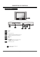
DESCRIPTION OF CONTROLS Front Panel Controls 3 TV/VIDEO MENU ON/OFF 1 VOL CH 7 5 2 4 1 ON/OFF 2 3 4 Index 5 6 Remote control sensor Standby indicator (Illuminates brightly when the TV is in standby mode. Dims when the TV is switched on.) TV/VIDEO MENU 7 VOL left/ right Volume(G) button increases the sound level and volume(F) button decreases the sound level. 8 CH (Channel) up / down These buttons work just as they do on your remote control.
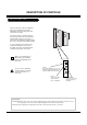
DESCRIPTION OF CONTROLS Rear Connections Panel Connecting external equipment to your TV. RF Connectors: Cable, Antenna Used to connect cable or antenna signals to the television, either directly or through your cable box. CALIBRATION Digital Audio Output Optical Connects to external audio equipment like a home theater system. Digital Audio Input Optical Connects to digital audio from various types of equipment.
DESCRIPTION OF CONTROLS Side Connections Panel There are four jacks on the lower-right front side of your TV that make connecting Audio/Video devices like video games and camcorders very simple. The jacks are like those found on the back jack connection panel. This means that most equipment that connects to those types of jacks on the rear jackpack, may be connected to the Side connection panel (FRONT VIDEO).
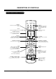
DESCRIPTION OF CONTROLS Remote Control Functions in TV Mode MODE Selects the remote operating mode: TV, VCR, Cable, DVD or Satellite. Select other operating modes, for the remote to operate external devices. TV INPUT MODE INDICATOR LIGHTS VCR CABLE DVD SAT TV Selects: TV and CATV. MODE TV/VIDEO Selects: Antenna, Cable, Video1, Video2, Front video, Component 1-2 and HDMI/DVI input sources.
DESCRIPTION OF CONTROLS Remote Control Functions in TV Mode VCR CABLE DVD SAT TV COMP2 Selects the Component 2 input source. MODE INDEX POWER TV/VIDEO COMP1 HDMI FRONT POWER TV INPUT COMP2 Turns your TV or any other programmed equipment on or off, depending on mode. FRONT HDMI Selects the front video input source. Selects the HDMI input source. 1 2 3 4 5 6 7 8 9 DASH(-) 0 FLASHBK NUMBER KEYPAD For direct channel selection and programming functions.
SPECIFICATIONS Product Specifications Model 32FZ4D-UA Horizontal Size (inches) Height (inches) Thickness (inches) Weight (pounds) 37.17 21.77 23.66 125.
ADJUSTMENT INSTRUCTIONS 4-2. Adjustment 1. Application Object (1) Select EZ Adjust 3. CUT-OFF, by pressing the ADJ key on the SVC Remote control. When it enters to adjustment mode, the pattern from a signal generator is being selected, it becomes with Normal image 16:9 and the CUT-OFF DRIVE data setting 31. (2) Connect the oscilloscope ground lead to GND on the CPT board and the probe to the GK pin connector of the CPT socket.
ADJUSTMENT INSTRUCTIONS 5-4. Raster H-center(H.CENTER) Adjustment 7. White Balance Adjustment Select 77. H Postion in the adjustment mode and adjust until left and right screen are symmetrically equal. Perform the screen adjustment first. Color Temp must be adjusted from Medium Mode. (The image condition must be adjusted from Normal condition) Manual adjustment is also possible by the following sequence. 5-5.
ADJUSTMENT INSTRUCTIONS (1) Select EZ Adjust 5. Sub Bright pressing ADJ key on the SVC Remote control. (2) Adjust to the point where “2” is not visible. 8-2. Sub COLOR, TINT Adjustment WHITE YELLOW CYAN GREENMAGENTA RED 1 3 B 1' BK M 3' BK C BK BLUE W (1) Select EZ Adjust 6. Sub Tint, Color pressing ADJ key on the SVC Remote control. (2) Select SUB COLOR and adjust the 1 and 1’ portion not to be classified. (3) Select SUB TINT and adjust the 3 and 3’ portion not to be classified.
PURITY & CONVERGENCE ADJUSTMENT Caution: 5. Reconnect the internal degaussing coil. Convergence and Purity have been factory aligned. Do not attempt to tamper with these alignments. However, the effects of adjacent receiver components, or replacement of picture tube or deflection yoke may require the readjustment of purity and convergence. 6. Position the beam bender locking rings at the 9 o'clock position and the other three pairs of tabs (2,4 and 6 pole magnets) at the 12 o'clock position.
PURITY & CONVERGENCE ADJUSTMENT 2 .ADJUST BEAM BENDER 2 POLE MAGNET TO GET FOUR EQUAL COLOR CIRCLES 1.ADJUST YOKE Z-AXIS FIRST TO GET EQUAL BLUE COLOR CIRCLES MAGNETS RED RED 8. Referring to above, perform the following two steps: a. Adjust the yoke Z-axis to obtain equal blue circles. b. Adjust the appropriate beam bender tabs to obtain correct purity (four equal circles). 9. After correct purity is set, tighten the yoke clamp screw and remove the two screen magnets. 5.
PURITY & CONVERGENCE ADJUSTMENT ROTATION DIRECTION OF BOTH TABS RING PAIRS MOVEMENT OF RED AND BLUE BEAMS B B OR OPPOSITE R 4 POLE SAME B R R OR B B R B OR OPPOSITE R R 6 POLE SAME B UP/DOWN ROCKING OF OF THETHE YOKE CAUSES UP/DOWN ROCKING YOKE OPPOSITE ROTATION ROTATION OF RED AND BLUE CAUSES OPPOSITE OF RED RASTERS AND BLUE RASTERS R OR B R LEFT/RIGHT OFTHE THE YOKE LEET/RIGHT ROCKING ROCKING OF YOKE CAUSES SIZECHANGE CHANGE CAUSES OPPOSITE OPPOSITE SIZE OFOF THE THERED REDAND AND
– – – BLOCK DIAGRAM - 16 -
BLOCK DIAGRAM - 17 -
BLOCK DIAGRAM - 18 -
NOTES - 19 -
EXPLODED VIEW 943 400 912 170 510 150 503 174 112 530 550 520 560 501 300 120 570 330 580 600 700 310 - 20 -
EXPLODED VIEW PARTS LIST No. Part No. Description 112 6335V32018B CPT ASSEMBLY,W76QEP257X V2NLGD N(+0.40G) 0G 120 6400VA0025C SPEAKER,FULLRANGE C163P03K1450 8OHM 15/20W 84DB 150 6140VC2006H COIL,DEGAUSSING AL 65TURN 14.5OHM 0.
REPLACEMENT PARTS LIST For Capacitor & Resistors, the charactors at 2nd and 3rd digit in the P/No. means as follows; LOCA. NO CC, CX, CK, CN : Ceramic CQ : Polyestor CE : Electrolytic PART NO RD : Carbon Film RS : Metal Oxide Film RN : Metal Film RF : Fusible DESCRIPTION RUN DATE : 2005.2.21 LOCA. NO PART NO IC601 0IMMRAL014B IC601 0IKE780500P SLA1003 SIP12 LF816 IC602 0IMCRMN027E MSP4440G QA B8 80P MULTI SOUND IC DESCRIPTION AT24C02N-10SI-2.
REPLACEMENT PARTS LIST LOCA. NO PART NO DESCRIPTION LOCA.
REPLACEMENT PARTS LIST LOCA. NO PART NO DESCRIPTION LOCA. NO PART NO DESCRIPTION D805 0DD414809ED 1N4148 TP GRANDE C120 0CK104DK56A 0.
REPLACEMENT PARTS LIST LOCA. NO PART NO DESCRIPTION LOCA. NO PART NO DESCRIPTION C1431 0CE106DK618 10UF STD 50V 20% C1650 0CK104DK56A 0.1UF 2012 50V 10% C1432 0CE226CR618 22UF SHL,SD 250V 20% C1651 0CE105CK636 1UF SHL,SD 50V 20% C1434 181-091W R 470PF 2KV 10%,-10% R/TP TP7.5 C1652 0CE105CK636 1UF SHL,SD 50V 20% C1435 181-091W R 470PF 2KV 10%,-10% R/TP TP7.
REPLACEMENT PARTS LIST LOCA. NO PART NO DESCRIPTION LOCA. NO C2611 0CE106SF6DC 10UF MVG 16V 20% C513 0CK104DK56A 0.1UF 2012 50V 10% C2612 0CE106SF6DC 10UF MVG 16V 20% C514 0CK104DK56A 0.1UF 2012 50V 10% C2613 0CE106SF6DC 10UF MVG 16V 20% C515 0CK104DK56A 0.1UF 2012 50V 10% C2631 0CE106SF6DC 10UF MVG 16V 20% C516 0CK104DK56A 0.1UF 2012 50V 10% C27 0CK104DK56A 0.1UF 2012 50V 10% C517 0CK104DK56A 0.1UF 2012 50V 10% C28 0CE105DK618 1UF STD 50V 20% C518 0CK104DK56A 0.
REPLACEMENT PARTS LIST LOCA. NO PART NO DESCRIPTION LOCA. NO PART NO DESCRIPTION C808 0CE227DP61A 220UF STD 160V 20% C972 0CE106DR618 10UF STD 250V M C809 0CE337DD618 330UF STD 10V 20% C973 0CE106DK618 10UF STD 50V 20% C810 181-091P SL 270PF 1KV 10%,-10% C974 0CE106DK618 10UF STD 50V 20% C811 0CE106DH618 10UF STD 25V M C975 0CE106DK618 10UF STD 50V 20% C812 0CE227DP61A 220UF STD 160V 20% C976 0CE336DP618 33UF STD 160V M C814 0CF2241L438 0.
REPLACEMENT PARTS LIST LOCA. NO PART NO DESCRIPTION LOCA. NO PART NO DESCRIPTION P901 387-J12J CONNECTOR ASSY,12P SHIELD(500) R1418 0RF0561K607 5.6 OHM 2 W 5.00% P905 387-A10G CONNECTOR ASSEMBLY,10P 2.5MM 400MM R1419 0RS1802K607 18K OHM 2 W 5.00% R1420 0RS1602K607 16K OHM 2 W 5.00% R1421 0RS1602K607 16K OHM 2 W 5.00% RESISTOR AR100 0RRZVTA001C 4.7K OHM 1 / 16 W 1608 5% R1424 0RS1501K607 1.5K OHM 2 W 5.00% AR101 0RRZVTA001C 4.
REPLACEMENT PARTS LIST LOCA. NO PART NO DESCRIPTION LOCA. NO PART NO DESCRIPTION R1967 0RD2702F609 27K OHM 1/6 W 5.00% R867 0RP0050H709 0.05 OHM 1/2 W 10% R1971 0RC0512H609 51 OHM 1/2 W 5.00% R904 0RD2202F609 22K OHM 1/6 W 5% R1972 0RC2200H609 220 OHM 1/2 W 5.00% R911 0RD3900F609 390 OHM 1/6 W 5% R1974 0RC2200H609 220 OHM 1/2 W 5.00% R911 0RS3900K619 390 OHM 2 W 5% TR R1975 0RC0512H609 51 OHM 1/2 W 5.00% R912 0RD0222F609 22 OHM 1/6 W 5.00% R1976 0RKZVTA001A 2.
REPLACEMENT PARTS LIST LOCA. NO PART NO DESCRIPTION LOCA.
Feb., 2005 Printed in Korea P/NO : 3828VD0156J CANADA: LG Electronics Canada, Inc. 550 Matheson Boulevard East Mississauga, Ontario L4Z 4G3 USA : LG Electronics Alabama Inc. P.O.Box 240007, 201 James Record Road, Bldg.
CPT MAIN(TOP) MAIN2 DIGITAL(TOP) DIGITAL(BOTTOM) MAIN(BOTTOM) LINE FILTER POWER SIDE A/V CONTROL