OWNER’S MANUAL Network Video Recorder Please read this manual carefully before operating your set and retain it for future reference. MODELS LRN3040N Series 1308 (V1.
Safety Information 1 Safety Information 1 Safety Information CAUTION This Class A digital apparatus complies with Canadian ICES-003. Cet appareil numérique de la classe A est conforme à la norme NMB-003 du Canada. RISK OF ELECTRIC SHOCK DO NOT OPEN Warning: Do not install this equipment in a confined space such as a bookcase or similar unit. CAUTION: TO REDUCE THE RISK OF ELECTRIC SHOCK DO NOT REMOVE COVER (OR BACK) NO USER-SERVICEABLE PARTS INSIDE REFER SERVICING TO QUALIFIED SERVICE PERSONNEL.
Safety Information Disposal of your old appliance 1. When this crossed-out wheeled bin symbol is attached to a product it means the product is covered by the European Directive 2002/96/EC. 3. The correct disposal of your old appliance will help prevent potential negative consequences for the environment and human health. 4. For more detailed information about disposal of your old appliance, please contact your city office, waste disposal service or the shop where you purchased the product.
Safety Information Safety warnings and Cautions 1 Safety Information The following are warnings and cautions for the safety of the users and for the prevention of any property damage. Please read the following carefully. WARNING • Turn off the system before installation. Do not plug in several electric devices to the same outlet. -- • -• This may cause an explosion. If the system’s HDD exceeds its life span, you may not be able to recover any data stored inside the HDD.
Safety Information 5 CAUTION Please beware of the following precautions before installing the system. Avoid positioning the product in any place where the unit may come into contact with moisture, dust, or soot. • Avoid placing in direct sunlight or near heating appliances. • Keep the product away from electric sparks or magnetic substances. • Do not place any conductive material through the ventilation grills. • Keep the system turned off before installation.
Contents Contents 17 General Explanation of the Live Screen on the Main Monitor 17 Main Monitor Screen 18 Moving the Channel's Position 18 Selecting the Split mode 18 Changing the order of cameras 19 PTZ Camera Control Safety Information 20 Using the Digital Zoom function 20 Export the recorded data 3 21 Viewing the System Log List 22 Viewing System Information 1 IMPORTANT SAFETY INSTRUCTIONS 2 22 Configuration menu Preparation 23 System settings 23 Properties 8 24 TCP
Contents 34 Emergency 48 Factory Default Configuration Settings 34 SNMP 54 Specifications 35 Output 35 Buzzer 35 1 User settings 35 Group Authority 36 User 36 7 2 Setup Wizard settings 36 Step 1 37 Step 2 37 Step 3 37 Step 4 3 4 4 Operation 38 Instant Recording 38 Panic Recording 39 Instant Playback 39 Search and Playback 39 Date and Time Search 39 Event Search 40 Bookmark/Protect Search 40 Export Search 41 Functions Available During Playback 42 Using th
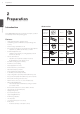
Preparation 2 Preparation 2 Preparation Introduction Accessories Model LRN3040N (4 Channel) is used for the description, operation and details provided in this operating guide. CD (Software and Owner's Manual) Mouse Remote Control AAA type batteries Features • Stable embedded Linux operating system. • Journal filing system for HDD file recovery following power recovery. • Internal storage expandable to 2 TB. • Easy operation using various user interface & user friendly GUI.
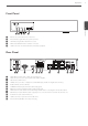
Preparation 9 Front Panel POWER HDD LAN 2 H.264 Network Video Recorder Preparation a b c d e a Remote Sensor: Point the remote control here. b Power Indicator: Lights when the system is powered. c HDD Indicator: Lights when the HDD is accessed. d NET Indicator: Blinks when the network is connected. e USB Port: Connects an external USB device for backup or playback. Rear Panel 2 RS 485 IN 4 ALARM IN USB 5V OUT - +1 23 4G12G 0.
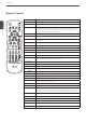
Preparation Remote Control Button POWER (1) LOGIN Description Turns system off. Displays the User Log-In dialog box or logs out. 2 ID Preparation VIEW Displays the split mode menu. CAM Displays the Monitor menu to set the first camera channel. ALM.OFF OSD SETUP wsad OK COPY SEARCH MARK Set the appropriate system ID to operate via the IR Remote Controller when using the multiple system. Press the ID button then press the number button within 2 seconds to select the system ID of the system.
Installation 11 3 Installation Connections Precautions 3 Depending on the camera and other equipment there are various ways to connect the unit. Please refer to the camera manual or manuals for other devices as necessary for additional connection information. • Be sure to switch off the camera before installation and connection. Basic Connection Overview Connect an external USB device for backup or playback. Connect audio (line input). Connect a mouse device.
Installation Connecting Display device Connecting Audio device This unit can be output simultaneously from the HDMI and VGA jack. The video signal connects between the system and the monitor. Connect the AUDIO OUT jacks on the unit to the mono audio in jacks on your audio device. Microphone and Speaker connection VGA Monitor connection Connect the VGA jacks on the rear of the unit to the corresponding input jacks on the TV or monitor using the VGA cable.
Installation USB External device LAN connection Connect the external device to the USB port. (Example: External HDD or other external storage.) Connect the LAN port to an available 10/100/1000 base-T port with a straight ethernet cable (not supplied). The NET indicator on the front panel will be lit. Mouse IP Camera connection Connect the USB mouse to operate the system. Connect the IP camera. After the installation, check the IP camera settings on the setup menu.
UT Installation Connecting LKD1000 Controller Connecting Alarm Input and Alarm Output This system has a data terminal. Use this port to connect keyboard (optional). RS-485 Terminal Alarm terminals are used to connect the alarm devices such as sensors, door switches, etc. Description - (DATA -) Data Transmission/Reception + (DATA +) Data Transmission/Reception GND Alarm Input You can connect up to 4 alarm sensors. Each alarm sensor should be connected with G (GND).
IO Installation HDD INSTALLATION Alarm Output Connect the alarm device to the alarm output. Alarm signal outputs when an event occur. 2 Alarm output connection RS 485 4 ALARM IN USB 5V OUT - + 1 2 34 G 1 2G VGA LAN 1 CAM 3 E-SATA ALARM IN 0.5 A DC 48 V Note for Hard Disk Drive HDMI RS 485 OUT The internal hard disk drive (HDD) is a fragile piece of equipment. Please follow the guidelines below when using the system to 2 protect against possible HDD failure.
Installation 2. Detach the top case by sliding it after removing the screws. You must lift up the top case verticality. Replacing the Hard Disk Drive Turn the power of the unit off and detach the power plug from the outlet. 1. Follow steps 1 to 3 described in “Installing the Hard Disk Drive”. 2. Remove the connector from the HDD. POWER HDD LAN H.264 Network Video Recorder 3. Remove the screws from the hard disk drive on the bottom of the hard disk mounting bracket. 4. Replace the new HDD. 3.
Installation System Operation General Explanation of the Live Screen on the Main Monitor 1. Turn on the unit. System booting will commence. The LG logo image will be displayed on the main monitor during the system booting. Main Monitor Screen 2. When the booting is completed the live window will be ab displayed. Click the 17 c d e f g h icon on the system control bar or press the LOGIN button on the remote control to display the log-in window. 3.
Installation Selecting the Split mode g System Control Bar Displays the CPU usage and Data traffic level of IP cameras. Displays date and time. ( ) Login (Logout) : Display the User Log-In dialog box or logs out. You can select the live screen mode to display a full or 4-split on the main monitor. 1. Press VIEW or click icon in the system control bar. 2. Select a screen mode. Search: Displays the search menu. Alarm Off: Turns the alarm off.
Installation PTZ Camera Control Preset Settings You can control the cameras connected via Network. 1. Select the PTZ camera channel on the main monitor you want to control. 2. Press PTZ or click the icon that appears when the mouse is moved to PTZ camera's screen. Virtual PTZ remote control is displayed on the main monitor. 3. Use each item to control the PTZ camera.
Installation Export the recorded data To Tour The Preset Positions You can tour all preset positions. 1. Press the TOUR button or Click the u icon. All registered preset positions in the camera will be selected and the camera position image will be switched on the active monitor. This unit can manually copy recorded images and audio from builtin HDD to the external recording devices. 1. Press COPY or click the icon in the system control bar. The [Video Export] menu appears. 2.
Installation NOTE • Check the export device before you proceed. • You can also use the COPY button on the remote control for export function. • If you use the external device, the external device has to be formatted on this unit. 21 Viewing the System Log List To view the system log list: 1. Press the LOG button or click the bar. icon in the system control 1. Connect the external device to the USB port on the front or the rear of the system. 2. Select the [Format] icon then press OK.
Installation Viewing System Information To view system information: 1. Press the INFO button or click the bar. Configuration menu icon in the system control The features and options of the system are configured through the menu. The operations of this unit can be set via a menu displayed on the main monitor. You can select and set the operational conditions by using the buttons on the remote control or using a Mouse connected to the unit.
Installation Setting the Menu Using the Remote Control Buttons Remote Control 23 System settings Description Use these buttons to select the menu options or adjust the options value. Properties Select the option or confirm the setting. Return to the previous menu or level. 3 1. Press SETUP to display the setup menu. Installation 2. Use w/s to select the desired menu item, then press OK to display the submenu. 3.
Installation TCP/IP v4 Network • Interface: Select a LAN port you want to use. • • DHCP: Select this option when a DHCP server is installed on the network to allow IP address assignment. With this setting, the IP address is assigned automatically. • IP Address: Enter the IP address. • Subnet Mask: Enter the subnet mask address. TCP/IP Port No.: Enter the TCP/IP Port number. You can watch the live surveillance image over the network with the PC Client program.
Installation When you want to change DDNS host name If you want to change the registered host name to new one, follow as shown below. 1. Enter a new host name in the [Host Name] option. 2. Press the [Update] button. The confirmation window will be displayed to change your host name. 3. Click the [OK] button. When host name is properly changed, the changed host name will be displayed in the [Registered Host] option. If host name is not changed after updating, please check network connection. 25 function.
Installation Update Backup This function is aimed at upgrade the system software. In this case, the current system settings are not deleted or replaced during the update process. 3 Installation • 1. Selects the update method. 2. Selects the device included update file or enter the FTP server name. NOTE If you select the update method to [LOCAL], the [FTP Server] option will be disabled and the [Device] option is activated.
Installation Daily/Weekly backup NOTE 1. Connect the USB device for backup. 2. Select WEEKLY or DAILY on the schedule options. 3. Select the backup device. • The backup function is not supported on the external USB CD-ROM driver. • Available external device for backup. 4. Enter the date and/or time to start backup on the schedule start option. 5. Enter the day of week and/or time on the Time Range Start option. 6. Enter the day of week and/or time on the Time Range End option. 7.
Installation Device settings IP Device -- Sensor: Select the sensor number on the drop-down list. -- In Use: Marks up when you want to activate the sensor. -- Sensor Type: Select the sensor type. -- Relay Output: Select the relay output number on the drop-down list. -- Relay Type: Select the relay type. -- Control Duration: Enter the relay time. Motion Setting You can configure this option when you select to [LGE] on the [Driver] option. Select [Motion] tab of the [Setup] window. 1.
Installation To register the IP device automatically To register the IP device manually 1. Click the [AUTO] button. 1. Click the [MANUAL] button. 2. The search window will be displayed and start to search the IP device automatically. By stopping or restarting the search, click [Stop] or [Refresh] button. 2. Enter the IP address. 4. Enter the [User Name] and the [Password] and then click the [Add] button. When you select several channels, channels are assigned same ID and password. 5.
Installation Display settings NOTE • If you register the IP camera for plug and connect, [HTTP Port] and [RTSP Port] number per each channel are assigned as below. CH HTTP Port RTSP Port 1 1080 1554 2 2080 2554 3 3080 3554 4 4080 4554 3 • If you connect the IP Camera which uses PoE for Plug and Connect port, it takes 2 or 3 minutes. Wait a moment. Installation • The information of IP camera for Plug and Connect port is not initialized if you use the [Factory Default] function.
Installation Record settings 31 2. Select a recording mode. Normal Schedule Recording A Normal schedule recoding can be activated at preset times, in a repeating pattern on selected weekdays. The system can record according to a schedule set by the user. It can also record manually regardless of date and time. The recording can be made either continuously or triggered by events (Sensor and motion detection).
Installation 3. Drag and drop with left button of the mouse to set the channel and time you want to record. The color of the time block is changed depending on the selected mode. 3. Use w/s/a/d to enter the necessary information for year, month and date. You can use the calendar icon to select the date. 4. Select the time cell block on the desired channel. NOTE If the special day recording schedule is duplicated with the other recordings, only the special day recording is possible.
Installation Sensor 33 Event settings Settings concerning sensor recording. Sensor 3 Installation • CH: Displays the channel number. • Prealarm: Specify the pre-event recording time. When the Event signal is detected, the system recordes the data before the event during the setting time. • In: Displays the number of the ALARM-IN terminal. Postalarm: Specify the post-event recording time. When the Event signal is detected, the system recordes the data after the event during the setting time.
Installation Mail Emergency • Notification: Mark up to be notified the unit's operating information according to notification settings by e-mail. • • SMTP Server: Enter the SMTP Server address. If notification option is not mark up and the SMTP server option is empty, the SMTP Port, User Name, Password and TLS options cannot be set. Notification: Mark up to be notified the emergency agent about the unit's operating information according to your notification settings.
Installation • Trap Community String: Specifies the SNMP trap community in which you want to enable this system (e.g. lgecommunity or public). Output 35 User settings Group Authority You can register a new user group with various access rights. 3 Installation • Relay Off -- ALARM ACKNOWLEDGE: Use the ALM.OFF button to stop alarm. -- POST-ALARM TIME: The alarm is stopped after post-alarm time.
Installation User You can set the user name for the selected User ID. Setup Wizard settings The Setup Wizard appears on the screen when you turn on the unit for the first time or select [Setup Wizard] on the Setup menu. You can set the system name, display language, date, time, network settings, recording schedule and recording mode on the initial setup wizard. NOTE If you run the Setup Wizard when system setup has already been completed, the data previously configured could be deleted.
Installation Step 2 Step 4 Set date and time. Set recording schedule. 37 3 Date: Select the current year, month and day. • Weekday: Sets the recording mode to weekday (Mon-Fri). • Time: Select the current time. • Weekend: Sets the recording mode to weekend (Sat-Sun). • Date Format: Select the date display format. • Time Format: Select the time display format. • Time Zone: Select the time zone in the area where the system is installed.
Operation 4 Operation 4 Operation Instant Recording Panic Recording Images from a camera will be recorded on the built-in hard disk. Ensure all the cameras are connected and that time and date have been set correctly. Before you start recording, first check the repeat recording settings in the recording menu of the system setup, and then make the recording settings. You can record the all channels at the same time. 1. Press the REC button and then press the channel button you want to record.
Operation Instant Playback 39 7. Press ad (Play) button or click button to start playback. The picture(s) is (are) displayed on the main monitor. 8. Press STOP (Z) to stop playback and return to the search menu. It is possible to play a recorded image without stopping recording. 1. Select a channel you want to playback. 2. Press ad (Play) button to play a recorded image of the previous 1 or 2 minutes of recording. The playback image will be displayed on the full screen window. 3.
Operation 5. Use w/s/a/d button to select the channel and press OK button to confirm the selection. If you want to select the all channels, marks up the [Select All] option. 6. Select the [Event Type] from the drop-down list. 7. Select the [Search] button then press OK. The event list menu appears. You can see the images through preview screen if you select a data in Event list. Export Search Searches an exported data in the external device.
Operation 41 Functions Available During Playback Button Playback Control Menu Function Remote Control Stops playback. Pauses playback. Jumps to the beginning of the current data recorded on the same date. (press the button for more than 2 seconds.) Press repeatedly to select the required scan speed. (dd, ddd, dddd, dddddor aa, aaa, aaaa, aaaaa) Press repeatedly to play frame-by-frame in pause mode. Press to play reverse or normal playback.
Operation Using the playback control menu Using the Protect function You can use various playback function using playback control menu. This function allows you to protect the recorded data against being automatically overwritten. 1. Play a data recorded. Playback control menu appears at the bottom of the screen. How to select Protect section. 1. Click icon on the Playback control menu. The [Protect] menu appears. 4 Selects the channel you want to play.
Troubleshooting 43 5 Troubleshooting Check the following guide for the possible cause of a problem before contacting service. Symptoms Cause & Solution Check the power cable is connected correctly. The system power does not turn on. Check the input voltage is correct. If the system power does not turn on even if the power cable is connected correctly, please contact the service center. Check the monitor power cable is connected properly. Make sure the monitor is turned on.
Troubleshooting Symptoms Cause & Solution Check the audio recording option is correctly set for the camera you wish to record audio. Audio data recorded with video data is not playing. Check the speaker on the rear of system are connected correctly. Check the connected speaker is working properly. Check the type of sensor in the camera setting is the same as with the connected sensor. The connected sensor is not operating.
Appendix 45 6 Appendix Recommended Devices Recommended USB Memory list No. Maker Model Name Capacity 1 LG Electronics XTICK SPIN 2G 2 LG Electronics XTICK UF1 32 G 3 Lexar Jump Drive 1G 4 Memorive SLC 2G 5 TRANSCEND JF 16 G 6 SKYDRV x2 2G 7 SANDISK Cruzer 16 G 8 Samsung Electronics SUM-LSB8 8G 9 Samsung Electronics SUM-PSB 32 G NOTE Some USB memory devices other than the ones on the above table may not work properly, even if this system reads them.
Appendix Supported function list for device Device Instant backup Schedule backup Export Configuration Import/Export USB memory O O O O USB HDD O O O O E-SATA HDD O O O O NOTE If you use a USB memory stick or USB HDD for configuration import/export you must disconnect the other external USB devices. Supported IP Camera Audio/Video Codec 6 Item Codec Video H.264 Base/Main Profile, JPEG, MPEG4 Audio G.711, G.
Appendix 47 Time zones Timezone Abbreviation Timezone Eniwetok, Kwajalein EK -12:00 Midway Island, Samoa MIS -11:00 Hawaii HAW -10:00 Alaska ALA -09:00 -08:00 Pacific Time (US and Canada); Tajuana PST -08:00 -07:00 Mountain Time (US and Canada), Chihuahua, La Paz, Mazatlan, Arizona MST -07:00 -06:00 Central Time (US and Canada), Saskatchewan, Guadalajara, Mexico City, Monterrey, Central America CST -06:00 -05:00 Eastern Time (US and Canada), Indiana (East), Bogota, Lima, Quito
Appendix Factory Default Configuration Settings 1st level 2nd level Properties TCP/IP4 6 Appendix System TCP/IP6 Network Network Streaming 3rd level Default Value Factory Default setting System Name NULL YES Language The option depends on the model.
Appendix NTP Controller System Update Backup Date Current Date NO Time Current Time NO Date Format YYYY/MM/DD YES Time Format 12 HR YES Time Zone The option depends on the model. NO Daylight Saving OFF NO Daylight Saving Start JAN, 1st, SUN, 00 NO Daylight Saving End JAN, 1st, SUN, 00 NO NTP OFF YES Time Server PUBLIC SERVER YES Private Time Server NULL YES Sync.
Appendix CH CH 01 - Name CH 01 to CH 04 YES Model Name NONE YES MAC NULL YES IP NULL YES HTTP Port 80 YES Driver NULL Profile1 NULL Profile2 NULL RTSP Port 554 YES RTP Mode UDP YES Stream NULL YES Audio Recording OFF YES Setup - - Delete - - Auto - - Manual - - 6 Overwrite ON YES Appendix Full Warning OFF YES Auto Delete OFF YES Storage Saving OFF NO Format - - E-SATA - - Insert - - Eject - - Channel Name ON YES Channel Status
Appendix Special Schedule Record Sensor Motion Sensor Event Notification Day Current day of the week NO Mode C+S+M NO Channel Copy - - Day Copy - - List Item 1 YES Name NULL YES Date --/-- YES Mode C+S+M NO Delete - - Channel Copy - - CH - - Prealarm 10 SEC YES Postalarm 10 SEC YES CH - - Prealarm 10 SEC YES Postalarm 10 SEC YES In - YES Sensor Type N.
Appendix Notification OFF YES SMTP Server NULL YES SMTP Port 25 YES User Name NULL YES Password NULL YES TLS OFF YES Mail Address 1 NULL YES Mail Address 2 NULL YES Mail Address 3 NULL YES Sender NULL YES JPEG Attachment OFF YES E-mail Test - - Notification OFF YES Host Name NULL YES Port 9002 YES SNMP Version NONE YES Port 161 YES 6 Community String public YES Appendix User NULL YES Authentication NONE YES Password NULL YES Privacy NONE
Appendix Group Authority User User Group ID GUEST YES Group Name GUEST YES Setup OFF YES Search/Play OFF YES Export OFF YES PTZ OFF YES Power Off OFF YES Instant Record OFF YES Main Channel All Enable YES User ID ADMINISTRATOR YES User Name ADMINISTRATOR YES Group ADMINISTRATOR YES Password "000000" YES Auto User Logout OFF YES 53 6 Appendix
Appendix Specifications Model LRN3040N Series Input Video Output Audio Appendix Storage Backup Network 1 HDMI 1 Output 1 Input 4 Output 2 Playback Speed Display VGA 1 Notification 6 4 Ch (Up to 5 Mega-pixel) Input Buzzer Support e-mail Support Remote S/W (Client S/W) Support Emergency S/W Support FF / Reverse 4 Steps (1x - 16x) Frame Advance Forward / Backward Alarm Search IP Screen Division Full, 4 Search Mode Date/Time, Event, Export, Protect, Bookmark Displ