Service Manual (LW20) LG Electronics 0
Contents Ch 1. Service information Ch 2. Locations Ch 3. System information · Specification · Model configuration · System Block Diagram · Fn key combinations · Status indicators · BIOS Flash · BIOS Setup Ch 4. Symptom-to-part index · Power system checkout · Numeric error codes · Error messages · LCD-related symptoms · Indeterminate problems Ch 5. Removing and replacing a part (FRU) Ch 6.
Ch1. Service information Chapter 1. Service information 1-1. Important service information Strategy for replacing parts (FRU-Field Replaceable Units) Before replacing parts Make sure that latest BIOS and drivers are installed before replacing any parts (FRUs) listed in this Use the following strategy to prevent unnecessary expense for replacing and servicing parts 1.
Ch1. Service information 1-2. Safety notices Warning Before the computer is powered-on after part (FRU) replacement, make sure all screws, springs, and other small parts are in place and are not left loose inside the computer. Verify this by shaking the computer and listening for rattling sounds. Metallic parts or metal flakes can cause electrical shorts. Warning some standby batteries contain a small amount of nickel and cadmium.
Ch1. Service information 1-3. Safety information General safety Follow these rules to ensure general safety · Observe good housekeeping in the area of the machines during and after maintenance. · When lifting any heavy object 1. Ensure you can stand safely without slipping. 2. Distribute the weight of the object equally between your feet. 3. Use a slow lifting force. Never move suddenly or twist when you attempt to lift. 4.
Ch1. Service information Electrical safety Observe the following rules when working on electrical equipment. Important Use only approved tools and test equipment. Some hand tools have handles covered with a soft material that does not insulate you when working with live electrical currents. Many customers have, near their equipment, rubber floor mats that contain small conductive fibers to decrease electrostatic discharges. Do not use this type of mat to protect yourself from electrical shock.
Ch1. Service information · Stand on suitable rubber mats (obtained locally, if necessary) to insulate you from grounds such as metal floor strips and machine frames. · Observe the special safety precautions when you work with very high voltages. These instructions are in the safety sections of maintenance information. Use extreme care when measuring high voltages. · Regularly inspect and maintain your electrical hand tools for safe operational condition. · Do not use worn or broken tools and testers.
Ch1. Service information Safety inspection guide The purpose of this inspection guide is to assist you in identifying potentially unsafe conditions. As each machine was designed and built, required safety items were installed to protect users and service personnel from injury. This guide addresses only those items. You should use good judgment to identify potential safety hazards due to attachment of non-LG features or options not covered by this inspection guide.
Ch1. Service information Handling devices that are sensitive to electrostatic discharge Any computer part containing transistors or integrated circuits (ICs) should be considered sensitive to electrostatic discharge (ESD). ESD damage can occur when there is a difference in charge between objects. Protect against ESD damage by equalizing the charge so that the machine, the part, the work mat, and the person handling the part are all at the same charge.
Ch1. Service information 1-4. Laser compliance statement When a CD-ROM drive, DVD drive or the other laser product is installed, note the following : Caution Use of controls or adjustments or performance of procedures other than those specified here in might result in hazardous radiation exposure. Opening the CD-ROM drive, DVD-ROM drive or the other optical storage device could result in exposure to hazardous laser radiation. There are no serviceable parts inside those drives.
Ch1. Service information 1-6. Read this first Before you go to the checkout guide, be sure to read this section. Important Notes · Only trained personnel certified by LG should service the computer. · Read the entire FRU removal and replacement page before replacing any FRU. · Use new nylon-coated screws when you replace FRUs. · Be extremely careful during such write operations as copying, saving, formatting. Drives in the computer that you are servicing sequence might have been altered.
Ch1.
Ch2. Locations Chapter 2.
Ch2. Locations Left view Line-in Connector / SPDIF Connector MIC Connector IEEE 1394 Connector VGA Connector Fan Louver USB Connector Headphone Connector LAN Connector Right view Emergency eject hole Optical Disk Drive Modem Connector ODD Eject Button ODD Open Button AC Connector Emergency eject hole Insert a thin and hard pin into this hole, and you can open the disc tray manually.
Ch3. System information Chapter 3. System information Specification - CPU · Dothan 1.6 ~ 2.1 GHz · μFCPGA - Main Chipset & Graphic · Intel 915GM,ICH6-M - Memory · 2SODIMM – Up to 2GB · DDR2 PC2-3200S/4200S Capable (400/533MHz) - HDD · 1.8" 5mm/8mm 30/40/60GB PATA Type - Communication · MDC · Modem, Daughter Card Type · Marvell Yukon 88E8053 PCI-E Gigabit Ethernet Controller · Marvell Yukon 88E8036 PCI-E 10/100 Ethernet Controller - Wireless LAN Solution · 802.
page48 15 page31 RJ45/RJ11 page44 Power rail & Battery Conn. page42 Miscellaneous page44 BATTERY CHARGER 5V/3.3V SYSTEM DC/DC page46 DDR2 DC/DC page47 GMCH_CORE VCCP page V1.2S / V1.5A Magnetic page31 page30 EEPROM HP/SPDIF SUB BD 5V 1.5V 3.3V 1.0V 1.8V 3.3V 3.3V MIC SUB BD SUB BD AMP 88E8036 page30 5V SUB B/D NEWCARD GbE SUB BD ALC880 AUDIO CODEC PORT 3 PORT 1 page37 MDC MODEM 88E8052 10/100 page13-15 AC’97 / AZALIA 1.
Ch3. System information Fn key combinations The following table shows the function of each combination of Fn with a function key. Function of Fn keys has nothing to do with Operating System. [Fn] + [F1] User defined Hot key. (available from OSD Setting) [Fn] + [F2] User defined Hot key. (available from OSD Setting) [Fn] + [F3] User defined Hot key. (available from OSD Setting) [Fn] + [F4] Forces the computer to enter power-saving mode.
Ch3. System information Status indicators The system status indicators show the status of the computer 1. 2. 3. 4. 5. 6. 1. Num lock Num lock indicator lights up when Num lock key is pressed. By pressing Fn + Scr LK (Num LK) key, you can use the embedded numeric keys. To disable the embedded numeric keys, press Fn + Scr LK (Num LK) key again.
Ch3. System information BIOS Flash You can update BIOS using a floppy disk drive. Because this system is not equipped with any floppy disk drive, you have to use an external USB drive for a BIOS update. In order to boot up with an USB drive, please set Removable Device as the first boot up drive in the boot menu of BIOS setup. · How to update flash ROM in DOS 1. Create ‘boot up’ flash update diskette. 2. Copy a ROM image file (*.wph) into the root of the flash update diskette. 3. Copy phlash16.
Ch3. System information BIOS Setup BIOS (Basic Input and Output System) Setup saves the system configuration in CMOS RAM, and check the configurations during startup. Use the BIOS Setup Utility to change and save the system environment, hardware configurations, power saving mode, etc. · Open the BIOS Setup Utility in the following situations : 1. to change the BIOS setup 2. to replace the backup battery 3. system configuration error occurs 4. to change the boot order 5.
Ch3. System information Using the keys The keys used in the BIOS Setup Utility and their functions are described at the bottom. · , + : General Help Display the descriptions of the keys used in the setup utility. · , : Select Item Navigate and select items in the setup utility. The selected item becomes highlighted. · , : Select Menu Move to another menu. · / , : Change Values Change the value of a selected item. · : Load Default Configuration Display Setup Confirmation window.
Ch3. System information Main menu System Time Current time. Use , , or keys to move around these fields. To change the value, press <+> or <−> key. System Date Today date. Use , , or keys to move around these fields. To change the value, press <+> or <−> key. Set any date from year 1981 to 2079. It will automatically keep track of leap years. The system date can also be set from the operating system. Product Name This shows the name of PC.
Ch3. System information Advanced menu Legacy USB Support There are two options to this field: Enabled, and Disabled. This field allows you to enable or disable the legacy USB support. Boot-time Diagnostic Screen Enables the Boot-time Diagnostic Screen. SATA Controller Mode Set SATA (Serial ATA) Controller Mode. AHCI Configuration Enables the AHCI (Advanced Host Controller Interface). Battery Charge Stop Percentage Set Battery Charge Stop Percentage. Fan Mode Control Set Fan Mode Control.
Ch3. System information Boot menu Boot menu enables you to set the boot order for the CD-ROM drive, Removable devices Hard drive, and Network boot as shown below. CD-ROM Drive Removable Devices Hard Drive B2 D0 Yukon PXE Exit menu Exit Saving Changes Select Exit Saving Changes to save new setup information in CMOS RAM. CMOS RAM stores the information using the backup battery; therefore, the information will not be lost when the computer is turned off.
Ch4. Symptom-to-part index Chapter 4. Symptom-to-part index The symptom-to-part index in this section lists symptoms and errors and their possible causes. The most likely cause is listed first. Note If replacing a part (FRU) does not solve the problem, put the original part back in the computer. Do not replace a non-defective FRU. Power system checkout · To verify a symptom, do the following : 1. Power off the computer. 2. Remove the battery pack. 3. Connect the AC adapter. 4.
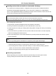
Ch4. Symptom-to-part index · Checking the AC adapter If the power-on indicator does not turn on, check the power cord of the AC adapter for correct continuity and installation. If the computer does not charge during operation, go to “Checking operational charging.” To check the AC adapter, do the following : 1. Unplug the AC adapter cable from the computer. 2. Measure the output voltage at the plug of the AC adapter cable. See the following figure: 3.
Ch4. Symptom-to-part index · If the voltage is not correct, replace the AC adapter. · If the voltage is acceptable, do the following : 1. Replace the system board. 2. If the problem persists, check the AC adapter whether it is correct product or not. Note Noise from the AC adapter does not always indicate a defect. · Checking operational charging 1.
Ch4. Symptom-to-part index · The Characteristics of the battery pack 1. Self-discharge The battery gradually loses its power over time without ever being used. 2. Periodic full discharge / charge Frequent recharge of the battery pack can reduce the capacity of the battery pack. When this happens, you can perform the full discharge / charge to improve the capacity. You should perform periodic full discharge /charge once every 30~60 days.
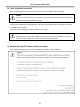
Ch4. Symptom-to-part index · To check the battery pack, do the following : 1. Power off the computer. 2. Remove the battery pack and measure the voltage between battery terminals 1(-) and 5(+). See the following figure : 5(+) 4 3 Terminal Voltage (V dc) 1 Ground(-) 5 +0V ~ +12.6V (6 cell) 2 1(-) 3. If the voltage is still less than +11.1 V DC after recharging, replace the battery. 4. If the voltage is more than +11.1 V DC, measure the resistance between battery terminals 1 and 2.
Ch4. Symptom-to-part index Numeric error codes Symptom / Error FRU or action, in sequence 0200 Fixed disk failure (The hard disk is not working) 1.Reset the hard-disk drive. 2.Load Setup Defaults in BIOS Setup Utility. 3.Hard-disk drive. 4.System board. 0210 Stuck Key error 1.Check the keyboard if it is pressed. 2.Replace the keyboard. 0211 Keyboard error Run interactive tests of the keyboard and the auxiliary input device. 0212 Keyboard Controller Failed System board.
Ch4. Symptom-to-part index Symptom / Error FRU or action, in sequence 0251 System CMOS checksum bad – System CMOS checksum is not correct. – Default configuration used. Replace the backup battery and run BIOS Setup Utility to reset the time and date. 0252 Password checksum bad – The password is cleared. Reset the password by running BIOS Setup Utility. 0260 System timer error 1. Replace the backup battery and run BIOS Setup Utility to reset the time and date. 2. System board.
Ch4. Symptom-to-part index Symptom / Error FRU or action, in sequence 02F7 Fail – Safe timer NMI failed 1. DIMM 2. System board 0611 IDE configuration changed 1. Load Setup Defaults in BIOS Setup Utility. 2. System board. 0612 IDE configuration error 1. Load Setup Defaults in BIOS Setup Utility. 2. System board. 0613 Com A configuration changed 1. Load Setup Defaults in BIOS Setup Utility. 2. System board. 0614 Com A configuration error 1. Load Setup Defaults in BIOS Setup Utility. 2.
Ch4. Symptom-to-part index Error message Symptom / Error FRU or action, in sequence Device address conflict. 1. Load Setup Defaults in BIOS Setup Utility. 2. Backup battery. 3. System board. Allocation error for device. 1. Load Setup Defaults in BIOS Setup Utility. 2. Backup battery. 3. System board. Failing bits: nnnn. 1. DIMM. 2. System board. Invalid System Configuration Data. 1. DIMM. 2. System board. I/O Device IRQ Conflict. 1. Load Setup Defaults in BIOS Setup Utility. 2. Backup battery.
Ch4. Symptom-to-part index LCD-related symptoms Note Before removing or disassembling LCD, power off the computer, unplug all power cords from electrical outlets, remove the battery pack also. Symptom / Error FRU or action, in sequence LCD screen becomes dark suddenly. Check out Battery Miser. Nothing displayed on LCD screen. 1. Check out Battery Miser. 2. Choose Never in the Turn off Monitor item on Power Options Properties. 3. Check the power save mode switch if it is pressed by something. 4.
Ch4. Symptom-to-part index Indeterminate problems · You are here because the diagnostic tests did not identify which adapter or device failed, wrong devices are installed, a short circuit is suspected, or the system is inoperative. Follow these procedures to isolate the failing FRU (do not isolate FRUs that have no defects). · Verify that all attached devices are supported by the computer. · Verify that the power supply being used at the time of the failure is operating correctly. 1.
Ch5. Removing and replacing a part Chapter 5. Removing and replacing a part (FRU) Danger Before removing any FRU, power off the computer, unplug all power cords from electrical outlets, remove the battery pack, and then disconnect any interconnecting cables. Caution Before the computer is powered on after FRU replacement, make sure that all screws, springs, and other small parts are in place and are not loose inside the computer. Verify metal flakes can cause electrical short circuits.
Ch5. Removing and replacing a part ■ 1010 Battery Pack 1. Push the battery latch in the direction shown below; then slide the battery pack out of the slot.
Ch5. Removing and replacing a part ■ 1020 Hard Disk Drive Remove the following parts in order before replacing this part. 1. Battery Pack(1010) 1. Remove 2 HDD Cover Screws. 2. Open HDD Cover, then remove HDD.
Ch5. Removing and replacing a part ■ 1030 Optical Disk Drive Remove the following parts in order before replacing this part. 1. Battery Pack(1010) 1. Push the ODD Knob in the direction shown below, then remove ODD from slot.
Ch5. Removing and replacing a part ■ 1040 Retainer Remove the following parts in order before replacing this part. 1. Battery Pack(1010) 2. Hard Disk Drive(1020) 1. Remove 2 Screws. No. FRU No. Specification Qty 1 1SZZBA4080A D4.0 X L4.0 2 2. Pull up the Hinge Cap using a (-) type screwdriver.
Ch5. Removing and replacing a part 3. Disconnect Retainer Connector. 4. Remove Retainer.
Ch5. Removing and replacing a part ■ 1050 Keyboard Remove the following parts in order before replacing this part. 1. Battery Pack(1010) 2. Hard Disk Drive(1020) 3. Retainer(1040) 1. Remove 12 Screws. No. FRU No. Specification Qty 1 1SZZBA4097B D4.5 X L6.5 12 2. Disconnect Keyboard Connector.
Ch5. Removing and replacing a part 2. Remove Keyboard.
Ch5. Removing and replacing a part ■ 1060 Display Module Remove the following parts in order before replacing this part. 1. Battery Pack(1010) 2. Hard Disk Drive(1020) 3. Retainer(1040) 4. Keyboard(1050) 1. Remove 2 Hinge Screws. (Left / Right) No. FRU No. Specification Qty 1 1SZZBA4097B D4.5 X L6.5 2 2. Remove Display Module.
Ch5. Removing and replacing a part ■ 1070 Key Deck Remove the following parts in order before replacing this part. 1. Battery Pack(1010) 2. Hard Disk Drive(1020) 3. Retainer(1040) 4. Keyboard(1050) 5. Display Module(1060) 1. Disconnect RTC Battery Connector then, remove RTC Battery. 2. Remove 7 Screws. No. FRU No. Specification Qty 1 1SZZBA4080A D4.0 X L4.
Ch5. Removing and replacing a part 2. Disconnect Touchpad Connector. 3. Remove Key Deck.
Ch5. Removing and replacing a part ■ 1080 Sub B/D Remove the following parts in order before replacing this part. 1. Battery Pack(1010) 2. Hard Disk Drive(1020) 3. Retainer(1040) 4. Keyboard(1050) 5. Display Module(1060) 6. Key Deck(1070) 1. Remove 5 Sub B/D Screws. No. FRU No. Specification Qty 1 1SZZBA4080A D4.0 X L4.0 5 2. Remove Sub B/D.
Ch5. Removing and replacing a part ■ 1090 Speaker Remove the following parts in order before replacing this part. 1. Battery Pack(1010) 2. Hard Disk Drive(1020) 3. Retainer(1040) 4. Keyboard(1050) 5. Display Module(1060) 6. Key Deck(1070) 7. Sub B/D(1080) 1. Remove 4 Speaker Screws. No. FRU No. Specification Qty 1 1SZZBA4027A D8.0 X L6.5 4 2. Remove Speakers.
Ch5. Removing and replacing a part ■ 1100 Fan Assembly Remove the following parts in order before replacing this part. 1. Battery Pack(1010) 2. Hard Disk Drive(1020) 3. Retainer(1040) 4. Keyboard(1050) 5. Display Module(1060) 6. Key Deck(1070) 7. Sub B/D(1080) 8. Speaker(1090) 1 1 1. Remove 5 Screws. 2 1 1 No. FRU No. Specification Qty 1 1SZZBA4020A D4.0 X L8.8 4 2 1SZZBZ4014C D2.0 X L5.0 1 2. Remove Fan Assy.
Ch5. Removing and replacing a part ■ 1110 Main Board Remove the following parts in order before replacing this part. 1. Battery Pack(1010) 2. Hard Disk Drive(1020) 3. Retainer(1040) 4. Keyboard(1050) 5. Display Module(1060) 6. Key Deck(1070) 7. Sub B/D(1080) 8. Speaker(1090) 9. Fan Assy(1100) 1. Remove ODD Plate. 2. Remove 3 Screws, then remove I/O Jack Sub Board. No. FRU No. Specification Qty 1 1SZZBA4080A D4.0 X L4.
Ch5. Removing and replacing a part 3. Remove a Screw, then remove Hinge Left. No. FRU No. Specification Qty 1 1SZZBA4080A D4.0 x L4.0 1 4. Remove a Screw, then remove Hinge Right. No. FRU No. Specification Qty 1 1SZZBA4080A D4.0 x L4.
Ch5. Removing and replacing a part 1 5. Remove 2 Screws and 1 Hexagon Screw. 1 2 No. FRU No. Specification Qty 1 1SZZBA4080A D4.0 X L4.0 2 2 1SZZBA4101A D2.0 x L11.5 1 6. Remove Main Board.
Ch5.
Ch5. Removing and replacing a part ■ 1120 Display Module Exploded View Remove the following parts in order before replacing this part. 1. Battery Pack(1010) 2. Hard Disk Drive(1020) 3. Retainer(1040) 4. Keyboard(1050) 5. Display Module(1060) 1. Remove 6 Rubber Caps, then remove 4 Screws. No. FRU No. Specification Qty 1 1SZZBA4104A D2.5 X L4.5 4 2. Remove LCD Front.
Ch5. Removing and replacing a part 3. Remove 4 Screws. No. FRU No. Specification Qty 1 1SZZBA4104A D2.5 X L4.5 4 4. Remove LCD Hinge. (Left / Right).
Ch5. Removing and replacing a part 5. Remove Inverter.
Ch5. Removing and replacing a part 6. Disconnect LED Sub Board Connector.
Ch5. Removing and replacing a part 7. Remove 2 Screws, then remove LED Sub Board. No. FRU No. Specification Qty 1 1SZZBA4041A D3.5 X L3.0 2 8. Remove LED Lens.
Ch5. Removing and replacing a part 9. Remove 2 Screws, then remove Left Antenna. No. FRU No. Specification Qty 1 1SZZBA4041A D3.5 X L3.0 2 10. Remove 2 Screws, then remove Right Antenna. No. FRU No. Specification Qty 1 1SZZBA4041A D3.5 X L3.
Ch5.
Ch5. Removing and replacing a part 12. Remove 4 Screws, then remove LCD Brackets. No. FRU No. Specification Qty 1 1SZZBA4041A D3.5 X L3.0 4 13. Disconnect LCD Cable.
Ch6. Part lists Chapter 6. Part lists 2005-06-20 Location Part Number Specification NCPU1 0IMCR00003A RH80536GE0462M LG INTEL 478P UFCPGA TRAY NT CPU PENTIUM-M 770 2.13GHZ/800MHZ C0-STEPPING(SL7SL) NCPU1 0IMCR00005A RH80536GE0412M LG INTEL 478P UFCPGA TRAY NT CPU PENTIUM-M 760 2.00GHZ/800MHZ C0-STEPPING(SL7SM) NCPU1 0IMCR00007A RH80536GE0362M LG INTEL 478P UFCPGA TRAY NT CPU PENTIUM-M 750 1.
Ch6. Part lists Location Part Number Specification NPLT2 3300BP4472A PLATE WINDRIVER HDD NCVR2 3550BM4200A WINDRIVER PCABS . ODD WEIGHT SAVER COVER NCVR3 3551B90003A WINDRIVER . RETAINER ASSY (수출향) NCVR4 3551B90004B WINDRIVER MEMORY DOOR ASSY NCVR5 3551B90005A WINDRIVER . 4 IN 1 ASSY NCVR6 3551B90006B WINDRIVER .
Ch6. Part lists Location Part Number Specification NNOB2 4940BM4175A WINDRIVER PCABS DRIVE KNOB LOCK NSPR1 4970BW4570A WD0.25MM ID3.0MM N9 L11.0MM 0.6KGF WINDRIVER BATEERY SPRING NANT2 5011B00026A HITACHI WIRELESS R WINDRIVER NANT1 5011B00027A HITACHI WIRELESS L WINDRIVER MKM16 5022BZ4025A THERMAL PCS-TC-11-T-13 19X19MM T130UM ZEBRA-2(MOBILE) GRAY K=4.7(W/M-C) NPADN 5022BZ4027A THERMAL SILICON 12X12MM, 0.5T HUNTER COH2003, DARK ORANGE, CONDUCTIVIEY 3.
Ch6. Part lists Location Part Number Specification NCAB5 6851B34040A MODEM CABLE 70 2 WINDRIVER, MDC CABLE NMDM2 6871BG867AB T60M893.05 FOXCONN 2 LAYERS 00L0 AZALIA MDC1.5 FORMFACTOR INTERNAL 56K MDC MODEM LF(LEAD FREE) NMDM2 6871BG869AA MA560-3 LF(LEAD FREE) QCOM 2 LAYERS 1A MDC1.5 FORM FACTOR V.92 MODEM CARD NMLB2 6871BWRGBAA N LGE 10 LAYERS REV 0.5 WINDRIVER MP GIGA MAIN B/D ASSY NMLB2 6871BWRTBAA N LGE 10 LAYERS REV 0.
Ch6.
Ch6. Part lists Location Part Number Specification NKBD2 3823B01167B NORWAY SILVER WINDRIVER SUNREX NKBD2 3823B01168A TAIWAN WINDRIVER SUNREX NKBD2 3823B01168B TAIWAN SILVER WINDRIVER SUNREX NMEM1 0IMMR00006B M470T6554BZ0-CD5 SAMSUNG ELECTRONICS 200P SODIMM BK 512MB 64MX64 533MHZ DDR2 SDRAM WITH 32MX16 PB FR NCSE2 3111B97125A WINDRIVER . CASE REAR SILVER LG LOGO NCSE2 3111B97125B WINDRIVER . CASE REAR BLUE LG LOGO NCSE2 3111B97126A WINDRIVER .
LW20 Location LG P/N NODD2 2026B10007A SPECIFICATION UJ-822BPT1-G PCC 8X 8X 24X 24X 10X 2X 2X 2.4X 2.4X 2X 24X NOTE BOOK 9.5MM ROHS WINDRIVER SUPER MULTI NODD2 NODD2 NBAT1 NBAT1 2029B09004A 2029B09005A 6911B00122A 6911B00122B GCC-4246N HLDS 8X 24X 24X 24X 9.5MM ROHS WINDRIVER COMBO ASSY UJDA765 PANASONIC 8X 24X 24X 24X 9.
LW20 2
LW20 Location LG P/N NSCRC 1SZZBA4017F NMDM2 6871BG867AB SPECIFICATION Screw, M2.0xL3.5bk REMARKS SCREW,DRAWING T60M893.05 FOXCONN 2 LAYERS 00L0 AZALIA PWB(PCB) MDC1.5 FORMFACTOR INTERNAL 56K MDC ASSEMBLY MODEM LF(LEAD FREE) MA560-3 LF(LEAD FREE) QCOM 2 LAYERS 1A MAIN PWB(PCB) NMDM2 6871BG869AA NCVR4 3551B90004B WINDRIVER MEMORY DOOR ASSY NCVR6 3551B90006B WINDRIVER .
LW20 Location LG P/N SPECIFICATION NSCR7 1SZZBA4097B NCSN1 3610BP4025A WINDRIVER RUBBER BOTTOM NNOB1 4940BM4174A WINDRIVER PCABS BATTERY KNOB KNOB NNOB2 4940BM4175A WINDRIVER PCABS DRIVE KNOB LOCK KNOB NLAN1 6718M000013 IEEE802.11G 54M 4 LAYERS REV 3.0 PRO/WIRELESS + D4.5 L6.5MM SWRH4 M2.5 H1.0 BK HUNTER TIP NO.0 ROHS 160 WM3B2200BGMWF INTEL INTERFACE STANDARD 2200BG LAN MINI WM3B2200BGRWF INTEL INTERFACE STANDARD NLAN1 6718M000014 IEEE802.11G 54M 4 LAYERS REV 3.
LW20 Location LG P/N NCAB2 6871BWRG7PA NPLT2 3300BP4472A SPECIFICATION WIMTEC 1 LAYERS - WINDRIVER TOSHIBA HDD FPC ASSY REMARKS PWB(PCB) ASSEMBLY,FPC PLATE WINDRIVER HDD MK3006GAL TOSHIBA 30GB EIDE INNER 4200RPM NHDD2 6744A00001A NHDD2 6744A00002A NHDD2 6744A00003A NHLD4 4930BM3101A WINDRIVER RUBBER HDD HOLDER NCVR3 3551B90003A WINDRIVER . RETAINER ASSY WIND RIVER MK4006GAH TOSHIBA 40GB EIDE INNER 4200RPM WIND RIVER MK6006GAH TOSHIBA 60GB EIDE INNER 4200RPM WIND RIVER" 5 PLATE HDD,1.
LW20 Location LG P/N SPECIFICATION NKBD2 3823B01150A KOREA WINDRIVER SUNREX 84KEY KBD ASSEMBLY NKBD2 3823B01151A US ENGLISH WINDRIVER SUNREX 84KEY KBD ASSEMBLY 6 REMARKS
LW20 Location LG P/N SPECIFICATION NKBD2 3823B01150B KOREA WINDRIVER SUNREX 84KEY SILVER KBD ASSEMBLY NKBD2 3823B01151B US ENGLISH WINDRIVER SUNREX 84KEY SILVER KBD ASSEMBLY NKBD2 3823B01152A US INTER WINDRIVER SUNREX KBD ASSEMBLY NKBD2 3823B01152B US INTER SILVER WINDRIVER SUNREX KBD ASSEMBLY NKBD2 3823B01153A RUSSIA WINDRIVER SUNREX KBD ASSEMBLY NKBD2 3823B01153B RUSSIA SILVER WINDRIVER SUNREX KBD ASSEMBLY NKBD2 3823B01154A ARABIC WINDRIVER SUNREX KBD ASSEMBLY NKBD2 3823B0
LW20 Location NSCR7 LG P/N 1SZZBA4097B SPECIFICATION + D4.5 L6.5MM SWRH4 M2.5 H1.0 BK HUNTER TIP NO.
LW20 Location LG P/N SPECIFICATION REMARKS LUS08 1SZZBA4080A + D4.0 L4.0MM SWRH4 M2 H1.
LW20 Location LG P/N NSUB2 6871BWRG0AA LUS08 1SZZBA4080A NCAB3 6850B32001A NCSN8 3610BM4034A SPECIFICATION N LGE 4 LAYERS REV0.5 WINDRIVER PILOT AUDIO BD ASSY PB FREE + D4.0 L4.0MM SWRH4 M2 H1.0 SILVER K2 TIP#0 AWM 20696 80C VW-1 32 . 36X16.5, 0.5PITCH KFC WINDRIVER, AUDIO BD TO MAIN BD WINDRIVER RUBBER MIC .
LW20 Location LG P/N NFAN2 5901B09287A SPECIFICATION THERMAL FAN ASSY WINDRIVER TOSHIBA THERMAL PCS-TC-11-T-13 19X19MM T130UM REMARKS FAN ASSEMBLY MKM16 5022BZ4025A NSPK1 6401B02547A . ESTEC 1.5W . . SPEAKER L WINDRIVER SPEAKER NSPK2 6401B02546A . ESTEC 1.5W . . SPECKER R WINDRIVER SPEAKER ZEBRA-2(MOBILE) GRAY K=4.7(W/M-C) + D8.0 L6.5MM MSWR3 / FN SPEAKER SILVER NSCRA 1SZZBZ4027A NSCRD 1SZZBZ4014C Screw, M2.0xL5.
LW20 Location LG P/N SPECIFICATION REMARKS LUS08 1SZZBA4080A + D4.0 L4.0MM SWRH4 M2 H1.0 SILVER K2 TIP#0 SCREW,DRAWING NSUB1 6871BWRG3PB SUB / N WIMTEC 4 LAYERS REV0.
LW20 13
LW20 Location LG P/N SPECIFICATION REMARKS LUS08 1SZZBA4080A + D4.0 L4.0MM SWRH4 M2 H1.0 SILVER K2 TIP#0 SCREW,DRAWING NCPU1 0IMCR00003A TRAY NT CPU PENTIUM-M 770 2.13GHZ/800MHZ RH80536GE0462M LG INTEL 478P UFCPGA C0-STEPPING(SL7SL) RH80536GE0412M LG INTEL 478P UFCPGA NCPU1 0IMCR00005A TRAY NT CPU PENTIUM-M 760 2.00GHZ/800MHZ C0-STEPPING(SL7SM) RH80536GE0362M LG INTEL 478P UFCPGA NCPU1 0IMCR00007A TRAY NT CPU PENTIUM-M 750 1.
LW20 Location LG P/N NSHT3 3858BP4482A . WINDRIVER SPEAKER GRILL LEFT SPECIFICATION SHEET (MECH) REMARKS NSHT5 3858BZ3038A . WINDRIVER SHEET INSULATION BOTTOM SHEET (MECH) NSHT6 3858BZ4498A .
LW20 Location LG P/N NSCRB 1SZZBA4104A NCSN3 4850BP4067A NCSN4 4850BP4068A NCSE3 3111B97122A SPECIFICATION + D2.5 L4.5MM MSWR3 / FN . BK WINDRIVER . WINDRIVER RUBBER DISPLAY FRONT UPPER 12.1INCH WINDRIVER RUBBER DISPLAY FRONT LOWER 12.
LW20 Location LG P/N NSCRB 1SZZBA4104A NHNG1 NHNG2 NINV1 NINV1 4775B00058A 4775B00057A 6708BI0096A 6708BI0097A SPECIFICATION + D2.5 L4.5MM MSWR3 / FN . BK WINDRIVER . WINDRIVER 6.5 KGF-CM HINGE LEFT LATCHLESS 12.1INCH REMARKS SCREW,DRAWING HINGE ASSEMBLY WINDRIVER 6.5 KGF-CM HINGE RIGHT LATCHLESS 12.
LW20 18
LW20 Location LG P/N HTO03 1SZZBA4041A NANT1 5011B00027A SPECIFICATION + D3.5 L3.0MM SWRH4 DUMMY COVER FIX SILVER MAGELLAN DISPLAY REMARKS SCREW,DRAWING HITACHI WIRELESS L WINDRIVER ANTENNA ANTENNA NANT2 5011B00026A HITACHI WIRELESS R WINDRIVER NLED1 3680BM4092A WINDRIVER PMMA LED DISPLAY 12.
LW20 Location LG P/N HTO03 1SZZBA4041A NBRK1 4810BP3353A WINDRIVER SUS LCD LEFT 0.5T 12.1INCH BRACKET NBRK2 4810BP3354A WINDRIVER SUS LCD RIGHT 0.5T 12.1INCH BRACKET NCAB4 6851B34039A LCD CABLE 100X147 25 WINDRIVER, WANSHIH NLCD2 6304FCI010A SPECIFICATION + D3.5 L3.0MM SWRH4 DUMMY COVER FIX SILVER MAGELLAN DISPLAY N121I1-L02 CHIMEI TFT COLOR 12.