ENGLISH OWNER’S MANUAL MONITOR SIGNAGE Please read this manual carefully before operating your set and retain it for future reference. MONITOR SIGNAGE MODELS M3204C www.lg.
Table of Contents Accessories Connecting the Stand Connecting the Speakers Portrait Mode Using the Remote Control Part Names and Functions Connecting to External Devices 3 4 5 6 7 9 10 Connecting to Your PC........................................................................................................10 Using the LAN.......................................................................................................................12 Daisy Chaining Set............................................
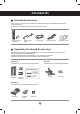
Accessories Included Accessories Thank you for your purchase. Check to make sure that the accessories shown immediately below have been included with your set. ❖ Note that the accessories may look different from those shown here. D-Sub Signal Cable Remote Control / Batteries Power Cable Audio Cable (PC) CD-ROM / Cards Separately Purchased Accessories Optional accessories are subject to change without prior notice to improve the performance of the set.
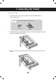
Connecting the Stand - Only on some models. 1. Take the parts for the stand out of the box and assemble them as shown in the picture. Parts First, check if the following parts are all present. Screws (4) Stand (2) 2. Place a soft cloth on a table and place the set screen side down upon the table. Connect the stand as shown below. 3. Use the screws to secure the stand on the rear side of the set as shown below.
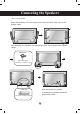
Connecting the Speakers - Only on some models. Attach the speakers to the set using screws as shown below. Then, connect the speaker cable. After installing your speakers, use holders and cable ties to organize the speaker cables. Cable holder Remove the paper. * This feature is not available on all models. When the speakers are installed. Cable ties *Connect the input terminal with the proper color match. * This feature is not available on all models.
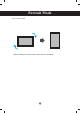
Portrait Mode - Only on some models. "When installing in portrait mode, rotate the set clockwise.
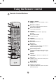
Using the Remote Control Remote Control Buttons 1 POWER On / Off Button - Switches the set on from standby or off to standby. 2 MONITOR On / Off Button - Turns off the monitor and then turn it back on. 3 Number and Letter Buttons - Type numbers and letters. 4 1/a/A Button - Selects numbers and letters. (SuperSign input only). 5 Volume Up/Down Button - Adjusts the volume. 6 PSM Button - Selects the Picture Status mode. 7 MUTE Button - Switches the sound on or off.
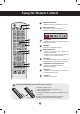
Using the Remote Control 14 ENERGY MONITOR INPUT 15 OFF ON .,! GHI PQRS 1/a/A TUV -*# CLEAR ABC JKL PSM Input List AV AUTO TILE OFF Component RGB HDMI/DVI SuperSign WXYZ 16 17 P BRIGHT A NESS G 18 E S.MENU 19 EXIT 16 CLEAR Button - Deletes the numbers and letters you typed (SuperSign input only). 17 ARC Button - Selects the Aspect Ratio mode. 18 BRIGHT NESS Button - Adjusts the resolution and brightness by pressing Up and Down.
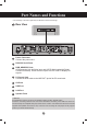
Part Names and Functions * The set image in the user's guide may be different from the actual image. Rear View 1 2 3 4 5 6 7 8 1 Power Connector Connect the power cord. 2 RS-232C Serial Ports 3 RGB, HDMI/DVI Ports HDMI supports high definition input and HDCP (High-bandwidth Digital Content Protection). Some devices require HDCP in order to display HD signals. 4 PC Sound Jack Connect the audio cable to the LINE OUT* jack of the PC sound card.
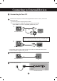
Connecting to External Devices Connecting to Your PC 1 Check that the computer, monitor and the peripherals are turned off. Then, connect the signal input cable. A. Connecting with a D-Sub Signal Input Cable. B. Connecting with an HDMI-DVI Signal Input Cable (not included) * When HDMI PC is used, a compatibility problem may occur. A. PC Rear back of the set.
Connecting to External Devices 4 1. Press Power. 2. Turn on the PC. Power button 5 Select an input signal. Press INPUT on the remote control to select the input signal. INPUT → ◄ ► → OK Or, press INPUT on the bottom of the set. INPUT → ◄ ► → AUTO/SET A. Connecting with a D-Sub Signal Input Cable. Select RGB: 15-pin D-Sub analog signal. Input List AV B. Component RGB HDMI/DVI SuperSign Connecting with an HDMI to DVI Signal Input Cable.
Connecting to External Devices Using the LAN 1 Connect the LAN cable as shown below. A. B. Connect PC to Monitor. Using a Router (Switch). LAN LAN Switch Set Set PC PC C. Using the Internet. Network LAN Network Set 2 PC Network Connect the LAN cable and install the eZ-Net Manager program on the CD-ROM. For more information about the program, please refer to the eZ-Net Guide on the included CD-ROM.
Connecting to External Devices Daisy Chaining Set A. Using RGB Input To use different set connected to each other, connect one end of the signal input cable (15-pin D-Sub signal cable) to the RGB OUT connector of set 1 and connect the other end to the RGB IN connector of other set. 15-pin D-Sub Signal Cable PC PC Set 1 Set 2 Set 3 Set 4 B.
Connecting to External Devices VESA FDMI Wall Mounting This set supports a VESA FDMI compliant mounting interface. These mounts are purchased separately and are not available from LG. Refer to the instructions included with your wall mount for more info. Kensington Security Slot The set is equipped with a Kensington Security System connector on the back panel. The cable and lock are available separately and are not sold by LG. For more info, visit http://www.kensington. com.
Connecting to External Devices Video Input 1 Connect the video cable as shown below and then connect the power cord (see page 10). Connecting with a BNC Cable •C onnect the input terminal with a proper color match. Set Audio Cable (not included) BNC Cable (not included) VCR/DVD Receiver 2 Select an input signal. Press INPUT on the remote control to select the input signal. INPUT → ◄ ► → OK Or, press INPUT on the bottom of the set. INPUT → ◄ ► → AUTO/SET Connecting with a BNC Cable Select AV.
Connecting to External Devices Component Input (480i/480p/576i/576p/720p/1080i) 1 Connect the AV cable as shown in the below figure, then connect the power cord (see page 10). • Connect the input terminal with the matching color. Set BNC Cable (not included) Audio Cable (not included) HDTV Receiver Note: - Some devices may require HDCP in order to display HD signals. - Component doesn't support HDCP. 2 Select an input signal. Press INPUT on the remote control to select the input signal.
Connecting to External Devices HDMI Input (480p/576p/720p/1080i/1080p) HDMI supports high definition input and HDCP (High-bandwidth Digital Content Protection). Some devices require HDCP in order to display HD signals. 1 Connect the AV cable as shown below and connect the power cord (see page 10). Set Set RCA-PC Audio Cable (not included) HDMI-DVI Signal Cable (not included) HDMI Signal Cable (not included) VCR/DVD/Set-top Box VCR/DVD/Set-top Box Note: Dolby Digital is not supported.
User Menus Screen Adjustment Options 2 6 3 1 Power Button 2 Power Indicator 3 MENU Button 4 OSD Select / Adjust Button 4 5 7 1 Turns the set on/off. This Indicator lights up green when the set is operating normally (on mode). If the set is in sleep mode (Energy Saving), the indicator color changes to amber. Shows/hides the OSD (On-Screen Display) menu. Selects an icon or adjusts the setting in the OSD menu. ▲ ▼ Adjusts up and down. ◄ ► Adjusts the volume.
User Menus Screen Adjustment Options 5 AUTO/SET Button [For PC Analog signal] Auto in progress For optimal display change resolution to 1360 x 768 [When XGA Mode is active and 1360 x 768 is selected] Auto in progress 6 INPUT Button INPUT → ◄ ► → AUTO/SET - Toggles between inputs AV Component RGB HDMI/DVI SuperSign Composite Video HDTV, DVD 15-pin D-Sub analog signal Digital signal SupeSign Input List AV 7 IR Receiver Component RGB HDMI/DVI SuperSign The sensor from which the set receives sig
User Menus OSD Menu Icon Function Description Adjusts screen brightness, contrast and color to your preference. Picture Adjusts the audio. Audio Adjusts the timer. Time Adjusts the screen status according to conditions. Option Adjusts tile options. Tile Adjusts USB options. USB Note OSD (On-Screen Display) • The OSD function enables you to adjust the screen status conveniently since it provides graphical menu representation.
User Menus Adjusting the OSD (On-Screen Display) MENU Pops up the menu screen ➩ ➩ Move where you want to adjust ➩ Select a menu icon ➩ ➩ Select a menu list Move where you want to adjust ➩ Adjust the status ➩ Save adjustment Exit from the menu screen. • Use the remote control to adjust the OSD. 1 Press MENU to bring up the OSD. 2 To access a control, use ▲▼. 3 When the icon you want becomes highlighted, press OK. 4 To access a control, use ▲▼.
User Menus Adjusting Screen Color Aspect Ratio PICTURE Move Aspect AspectRatio Ratio ꕫ Energy Saving 16:9 :: 16:9 : Off Picture Mode : Standard ꔋ 16:9 16:9OK Justꔋscan Original 4:3 • Backlight 70 14:9 • Contrast 90 Zoom • Brightness 50 • Sharpness 70 • Color 60 Cinena Zoom 1 Full Wide ▼ To select the image size of the screen. 16:9: Widescreen mode. Just Scan: D isplays the full signal data without cropping any of the image.
User Menus Adjusting Screen Color Energy Saving PICTURE Move Aspect Ratio : 16:9 ꕫ Energy Saving : Off Picture Mode : Standard OK ꔋ Off Offꔋ Level 1 • Backlight 70 • Contrast 90 • Brightness 50 • Sharpness 70 • Color 60 Level 2 Level 3 ▼ The screen brightness adjusting menu helps you save energy. Level: 4 screen brightness levels are available.
User Menus Adjusting Screen Color Picture Mode PICTURE Move Aspect Ratio OK : 16:9 ꕫ Energy Saving : Off Picture PictureMode Mode Standard :: Standard • Backlight 70 • Contrast 90 • Brightness 50 • Sharpness 70 • Color 60 ▼ Vivid ꔋ Standard Standard ꔋ Cinema Sport Game Expert 1 Expert 2 The picture mode menu toggles between screen presets. Standard: This is the optimum viewing condition for general users. Vivid: Displays a sharp image.
User Menus Adjusting Screen Color Picture Mode PICTURE Move Aspect Ratio : 16:9 ꕫ Energy Saving : Off Picture Mode : Standard (User) Backlight 70 70 •• Backlight • Contrast OK ꔋ 90 • Brightness 50 • Sharpness 70 • Color 60 ▼ Backlight: Adjusts the brightness of LCD panel. Contrast: Adjusts the difference between light and dark levels. Brightness: Adjusts the brightness of the screen. Sharpness: Adjusts the clearness of the screen (function works in DTV mode).
User Menus Adjusting Screen Color Advanced Control PICTURE Move OK ▲ • Contrast 90 • Brightness 50 ◄ Medium ► High • Sharpness 70 Dynamic Contrast • Color 60 Dynamic Color 0 Noise Reduction ꔋ Gamma • Tint • Advanced Control • Picture Reset Screen Color Temperature High Medium Medium Black Level High Film Mode Off Close Color Temperature: Color Settings Cool: Slightly purple temperature. Medium: Slightly blue temperature. Warm: Slightly red temperature.
User Menus Adjusting Screen Color Picture Reset PICTURE Move Returns Picture Mode to the default factory settings. OK ▲ • Contrast 90 • Brightness 50 • Sharpness 70 • Color 60 • Tint 0 • Advanced Control • Picture Reset ꔋ Screen Screen PICTURE Move OK ▲ • Contrast 90 • Brightness 50 • Sharpness 70 SCREEN • Color 60 Resolution ► 0 Auto Config. • Tint • Advanced Control • Picture Reset Screen Screen Move BACK Prev.
User Menus Adjusting Audio AUDIO Move Auto Auto Volume Volume Off :: Off Clear Voice II : Off • Level Balance Sound Mode AUDIO OK ꔋ Clear Voice II Balance 0 Sound Mode : Standard 50 • Bass 50 OK : Off • Level 3 • Treble Move ▲ 3 0 : Standard • Treble 50 • Bass 50 • Reset • Reset Speaker ▼ : On Auto Volume Automatically adjusts uneven sound volumes across all channels or signals to the most appropriate level. To use this feature, select On.
User Menus Adjusting the Timer TIME Move OK ꔋ Clock Clock Off Time : Off On Time : Off Sleep Timer : Off Auto Off : On Power On Delay : Off Clock If the current time is incorrect, reset the clock manually. 1) Press MENU button and then use ▼▲ button to select the Time menu. 2) Press ► and then use ▼▲ to select the Clock menu. 3) Press ► and then use ▼▲ to set the hour (00h to 23h). 4) Press ► and then use ▼▲ to set the minutes (00 min to 59 min).
User Menus Selecting Options OPTION Language Language Input Label Move English ::English Key Lock : Off Set ID : Off ISM Method : Normal DPM Select : On Power Indicator : ON Logo Light : ON OK ꔋ ▼ Language Chooses the language in which the control names are displayed. Input Label Selects a label for each input source. Key Lock Use ▼▲ to select On or Off. The set can be set up so that it can only be used with the remote control. This feature can prevent unauthorized viewing.
User Menus Selecting Options OPTION Move OK ▲ ISM Method : Normal DPM Select Power Indicator : On : ON Logo Light : ON Ineterface Select : RS232C ꔋ Network Setup Information Factory Reset DPM Select Turns power saving on/off. Power Indicator Sets the power indicator on the front side of the set to On or Off. If you set to Off, it will go Off. If you set On at any time, the power indicator will automatically be turned on.
User Menus Screen Tiling Options Tile Mode TILE Move Tile Mode : 2x2 Off Tile ID :0 Natural Mode : Off H Size :0 V Size :0 H Position : 0 V Position : 0 OK ꔋ - M ust be displayed with various other set. -M ust be in a function that can be connected to RS-232C or RGB Out. - Tile Mode works with several set to enlarge the screen area. Reset Select Tile Mode and choose Tile alignment and set the ID of the current set to set the location.
User Menus Screen Tiling Options - Tile Mode (set 1 to 9): c(3) x r(3) Column ID 1 ID 2 ID 3 ID 4 ID 5 ID 6 ID 7 ID 8 ID 9 Row - Tile Mode (set 1 to 2): c(2) x r(1) Column ID2 ID1 Row - Tile Mode (set 1 to 16): c(4) x r(4) Column ID 1 ID 2 ID 3 ID 4 ID 5 ID 6 ID 7 ID 8 Row ID 9 ID10 ID 11 ID 12 ID 13 ID 14 ID 15 ID 16 Tile ID: Select the location of the Tile by setting an ID. Natural: Omits the distance between the screens allowing the image to be displayed naturally.
User Menus USB Options Connecting USB Devices When you connect a USB device, this pop-up menu is displayed, automatically. The pop-up menu will not be displayed while the OSD, EPG or Schedule list is displayed. When the pop-up menu appears, you can select Music List, Photo List or Movie List in the MY MEDIA menu. You cannot add a new folder or delete an existing folder on the USB device while it is connected to the set. 1. Connect the USB device to the USB jack on the set. USB 메모리 스틱 2.
User Menus USB Options Precautions when using the USB device • • • • • • • • • • • • • • • • • • Only a USB storage device is recognizable. If the USB storage device is connected through a USB hub, the device is not recognizable. A USB storage device using an automatic recognition program may not be recognized. A USB storage device that uses its own driver may not be recognized. The recognition speed of a USB storage device may depend on each device.
User Menus USB Options Photo List You can view photo files on USB storage devices. The On-Screen Display may be different from your set. Images are an example to assist with set operation. Supported JPG Photo File Types Baseline: 15360 x 8640 Progressive: 1024 x 768 • You can view JPG files only. • Non-supported files are displayed in the form of bitmap.
User Menus USB Options Photo Selection and Pop-Up Menu USB Device Photo List Page 2/3 Drive1 JMJ001 1366x768, 125KB Up Folder Navigation No Marked Free Space 150 MB Up Folder KY103 02/12/2010 02/12/2010 KY101 02/12/2010 KY104 KY102 02/12/2010 KY105 02/12/2010 JMJ001 02/12/2010 JMJ005 02/12/2010 JMJ002 02/12/2010 JMJ006 02/12/2010 JMJ003 02/12/2010 JMJ007 02/12/2010 JMJ004 02/12/2010 JMJ008 02/12/2010 Option Page Change MARK Mark EXIT Exit ➩ View: Displays the selected
User Menus USB Options Viewing Photos Detailed operations are available on the full-sized photo view screen. The aspect ratio of a photo may change the size of the photo displayed on the screen in full-size. Press EXIT to move to the previous menu. ◄ Slideshow ◘ BGM ◘ 1/17 ꘤ ► Delete Option Hide ►► Slideshow When no picture is selected, all photos in the current folder are displayed during slide show. If some photos are selected, those photos are displayed in a slide show.
User Menus USB Options Music List You can play music files stored on USB storage devices. Purchased music files (*.MP3) may have copyright restrictions. Playback of these files may not be supported by this set. The On-Screen Display may be different from your set. Images are an example to assist with set operation. Supported MP3 Audio File Types Bit rate 32 to 320kbps • Sampling rate MPEG1 layer 3: 32 kHz, 44.1 kHz, 48 kHz.
User Menus USB Options Music Selection and Pop-Up Menu Up to 6 music files are listed per page. Play (During stop): Plays the selected music files. When playback of a file stops, the next selected file will be played. When there are no selected music files left to play, the next file in the current folder will be played. If you go to a different folder and press OK, the current file being played will stop. Play Marked: Plays the selected music files.
User Menus USB Options If you don't press any button for a while during playback, the play information box (as shown below) will display as a screen saver. What is the ‘Screen Saver’? The screen saver prevents screen pixel damage due to a fixed image remaining on the screen for an extended period of time. Music S003 0:27 / 3:67 Note • • • • • Damaged or corrupted music cannot be played and displays 00:00 in playtime.
User Menus USB Options Movie List The movie list is activated once a USB device is detected. It is used when playing movie files on the set. Movies in the USB folder can be played. Video editing is not supported but files can be deleted. It is a movie list that displays folder information and DivX files. The movie list supports up to four drives. Supported AVI/DivX Movie File Types Video format: MPEG1, MPEG2, MPEG4 (Microsoft MPEG 4-V2, V3 file types are not supported), DivX3.xx, DivX, 4.xx, DivX5.
User Menus USB Options Screen Components 2 Movie List Page 2/3 Movie M002 4 3 USB Device No Marked Free Space 150 MB Title Duration Up Folder Favorite Music M001 640x480, 720KB 1 Up Folder Navigation M002 01:34:15 M001 01:35:30 M001 01:30:20 Option 5 Page Change 1 Moves to the Upper Level Folder 2 Current Page/Total Pages 3 Total Number of Marked Movie Files 4 Usable USB Memory 5 Corresponding Buttons on the Remote Control Note • MARK Mark EXIT Exit Use < > to move f
User Menus USB Options Movie Selection and Pop-Up Menu USB Device Movie List Page 2/3 No Marked Free Space 150 MB Title Movie M002 Duration Up Folder Favorite Music M001 640x480, 720KB 01:34:15 M001 01:35:30 01:30:20 M001 Up Folder Navigation M002 Option Page Change MARK Mark EXIT Exit ➩ USB Device Movie List Page 2/3 Duration 1366x768, 125KB Favorite Music Play M001 Mark All M002 Delete 01:34:15 M001 Close 01:35:30 Mark EXIT 01:30:20 M001 Up Folder Note Free Space
User Menus USB Options Using the remote control ◄◄ / ►► II < > Play(►) When playing, repeatedly, press REW (◄◄) to speed up ◄◄(x2) -> ◄◄◄ (x4) -> ◄◄◄◄(x8) -> ◄◄◄◄◄(x16) ->◄◄◄◄◄◄(x32). Repeatedly, press FF (►►) to speed up ►►(x2)-> ►►► (x4) -> ►►►► (x8) -> ►►►►►(x16) -> ►►►►►►(x32). Pressing these buttons repeatedly increases the fast forward/reverse speed. During playback, press Pause (II) and the still screen is displayed. Press Pause (II) and then use FF (►►) for slow motion.
User Menus USB Options DivX Registration Code USB Move OK Photo List Music List Movie List DivXReg. DivX Reg.Code Code Deactivation DivX(R) Video On Demand ꔋ Your registration Code is: xxxxxxxxxx To learn more visit www.divx.com/vod. Close Confirm the DivX registration code of the set. Using the registration code, movies can be rented or purchased at www.divx.com/vod. With a DivX registration code from another set, playback of rented or purchased DivX files is not allowed.
User Menus USB Options Deactivation USB Move OK Photo List Music List Movie List DivX Reg. Code Deactivation DivX(R) Video On Demand ꔋ Do you want to deactivate your device? Yes No ➩ DivX(R) Video On Demand This device is deactivated. Your deactivation code is: xxxxxxxx To learn more visit www.divx.com/vod. Close Deactivating devices allows users who have activated all the available devices through the web server and are blocked from activating more devices.
Troubleshooting No Image is Displayed ● Is the power cord connected? • See if the power cord is properly connected to the outlet. ● Is the power indicator light on? • See if the power switch is turned on. • May need service. ● Power is on, power indicator is green but the screen appears extremely dark. • Adjust brightness and contrast again. • Backlight may need repair. ● Is the power indicator amber? • If the set is in power saving mode, move the mouse or press any key.
Troubleshooting The Screen Image Looks Abnormal ● Is the screen position wrong? • D-Sub analog signal - Press AUTO on the remote control to automatically select the optimal screen status that fits the current mode. If adjustment is not satisfactory, use the OSD Position menu. • See if the video card resolution and frequency are supported by the television.
Troubleshooting The Audio Does Not Work ● No sound? • See if the audio cable is connected properly. • Adjust the volume. • See if the sound is set properly. ● Sound is too dull. • Select the appropriate equalizer setting. ● Sound is too low. • Adjust the volume. Screen Color is Abnormal ●S creen has poor color resolution (16 colors). • Set the number of colors to more than 24 bits (true color) Select Control Panel - Display - Settings - Color Table menu in Windows.
Specifications LCD Panel 80.0 cm (31.5 inch) TFT (Thin Film Transistor) LCD (Liquid Crystal Display) Panel Visible diagonal size: 80.0 cm 0.51075 mm Power Rated Voltage Power Consumption Dimensions & Weight AC 100-240 V~ 50 / 60 Hz 1.6 A On Mode :100 W Typ. Sleep Mode :≤ 1 W (RGB) / 2 W (HDMI/DVI) (If LAN OFF is selected) Off Mode :≤ 0.5 W [2] [1] H W H D W [4] [3] H H W D D W D Width x Height x Depth [1] 80.29 cm (31.61 inch) x 53.18 cm (20.93 inch) x 30.19 cm (11.
Specifications Video Signal Max. Resolution RGB: 1600x1200 @ 60 Hz HDMI/DVI: 1 920x1080 @ 60 Hz - It may not be supported depending on the OS or video card type. Recommended Resolution RGB: WXGA 1360x768 @ 60 Hz HDMI/DVI: WXGA 1360x768 @ 60 Hz - It may not be supported depending on the OS or video card type.
Specifications PC Mode - Preset Mode Preset Mode Horizontal Frequency (kHz) Vertical Frequency (Hz) 640 x 350 720 x 400 640 x 480 640 x 480 800 x 600 800 x 600 832 x 624 1024 x 768 1024 x 768 1280 x 720 31.469 31.468 31.469 37.5 37.879 46.875 49.725 48.363 60.123 44.772 70.8 70.8 59.94 75 60.317 75 74.55 60 75.029 59.855 1 2 *3 4 *5 6 7 *8 9 *10 Preset Mode *11 *12 *13 *14 15 *16 17 *18 Vertical Frequency (Hz) 47.7 47.72 47.7 63.981 79.98 65.290 75.0 67.5 60 59.799 60 60.02 75.02 59.
RS-232C Controlling Controlling the Multiple Multiple Product Set Use this method to connect several products to a single PC. You can control several products at a time by connecting them to a single PC. If the [Set ID] menu in [Option] is set to OFF, the monitor ID value should be set between 1 and 99. Connecting the cable Connect the RS-232C cable as shown in the picture. You need to purchase a cable to connect the RS-232C socket as it is not provided as the accessory.
RS-232C Controlling Multiple Set Command Reference List COMMAND 1 COMMAND 2 01. Power 02. Input Select 03. Aspect Ratio 04. Screen Mute 05. Volume Mute 06. Volume Control 07. Contrast 08. Brightness 09. Color 10. Tint 11. Sharpness 12. OSD Select 13. Remote Lock/ key Lock 14. Balance 15. Color Temperature 16. Abnomal state 17. ISM mode 18. Auto configuration 19. Key 20. Tile Mode 21. Tile H Position 22. Tile V Position 23. Tile H Size 24. Tile V Size 25. Tile ID Set 26. Natural Mode (In Tile mode 27.
RS-232C Controlling Multiple Set COMMAND 1 COMMAND 2 38. Scheduling input select 39. Sleep Time 40. Auto Sleep 41. Power On Delay 42. Language 43. DPM Select 44. Reset 45. Power Saving 46. Power Indicator 47. Logo Indicator 48. Serial no. 49. S / W Version 50.
RS-232C Controlling Multiple Set Transmission / Receiving Protocol Transmission [Command1][Command2][ ][Set ID][ ][Data][Cr] * [Command 1]: First command. (k, j, m, d, f, x) * [Command 2]: Second command.(a to u) * [Set ID]: Set up the Set ID number of product. range : 01H to 63H. by setting '0', server can control all products. * In case of operating with more than 2 sets using set ID as '0' at the same time, it should not be checked the ack message.
RS-232C Controlling Multiple Set Transmission / Receiving Protocol 01. Power(Command : a) ► To control Power On / Off of the Set. Transmission [k][a][ ][Set ID][ ][Data][Cr] Data 0 : Power Off 1 : Power On Acknowledgement [a][ ][Set ID][ ][OK][Data][x] ► To show the status of Power On / Off. Transmission [k][a][ ][Set ID][ ][FF][Cr] Acknowledgement [a][ ][Set ID][ ][OK][Data][x] Data 0 : Power Off 1 : Power On 02. Input Select (Command : b) (Main Picture Input) ► To select input source for the Set.
RS-232C Controlling Multiple Set Transmission / Receiving Protocol 03. Aspect Ratio(Command : c) (Main picture format) ► To adjust the screen format. You can also adjust the screen format using the ARC (Aspect Ratio Control) button on remote control or in the Screen menu.
RS-232C Controlling Multiple Set Transmission / Receiving Protocol 05. Volume Mute(Command : e) ► To control On/Off of the Volume Mute. Transmission [k][e][ ][Set ID][ ][Data][Cr] Data 0 : Volume Mute On (Volume Off) 1 : Volume Mute Off (Volume On) Acknowledgement [e][ ][Set ID][ ][OK][Data][x] Data 0 : Volume Mute On (Volume Off) 1 : Volume Mute Off (Volume On) 06.
RS-232C Controlling Multiple Set Transmission / Receiving Protocol 07. Contrast(Command : g) ► To adjust screen contrast. You can also adjust the contrast in the Picture menu. Transmission [k][g][ ][Set ID][ ][Data][Cr] Data Min : 00H to Max : 64H Acknowledgement [g][ ][Set ID][ ][OK][Data][x] * Refer to 'Real data mapping' page A7. 08. Brightness(Command : h) ► To adjust screen brightness. You can also adjust the brightness in the Picture menu.
RS-232C Controlling Multiple Set Transmission / Receiving Protocol 09. Color(Command : i) (Video Timing only) ► To adjust the screen color. You can also adjust the color in the Picture menu. Transmission [k][i][ ][Set ID][ ][Data][Cr] Data Min : 00H to Max : 64H (Hexadecimal code) * Refer to 'Real data mapping' page A7. Acknowledgement [i][ ][Set ID][ ][OK][Data][x] Data Min : 00H to Max : 64H 10. Tint(Command : j) (Video Timing only) ► To adjust the screen tint.
RS-232C Controlling Multiple Set Transmission / Receiving Protocol 11. Sharpness(Command : k) (Video Timing only) ► To adjust the screen Sharpness. You can also adjust the sharpness in the Picture menu. Transmission [k][k][ ][Set ID][ ][Data][Cr] Data Min : 00H to Max : 64H (Hexadecimal code) * Refer to 'Real data mapping' page A7. Acknowledgement Data [k][ ][Set ID][ ][OK][Data][x] Min : 00H to Max : 64H 12. OSD Select(Command : l) ► To control OSD on/off to the set.
RS-232C Controlling Multiple Set Transmission / Receiving Protocol 14 Balance(Command : t) ► To adjust the sound balance. Transmission [k][t][ ][Set ID][ ][Data][Cr] Data Min : 00H to Max : 64H (Hexadecimal code) 00H : Step L50 64H : Step R50 Acknowledgement [t][ ][Set ID][ ][OK][Data][x] Data Min : 00H to Max : 64H 00H : Step 0 to L50 64H : Step 100 to R50 * Balance : L50 to R50 15. Color Temperature (Command : u) ► To adjust the screen color temperature.
RS-232C Controlling Multiple Set Transmission / Receiving Protocol 16. Abnormal state (Command : z) ► Abnormal State : Used to Read the power off status when Stand-by mode.
RS-232C Controlling Multiple Set Transmission / Receiving Protocol 18. Auto Configure(Command: j u) ► To adjust picture position and minimize image shaking automatically. it works only in RGB(PC) mode. Transmission [j][u][ ][Set ID][ ][Data][Cr] Data 1 : To set Acknowledgement [u][ ][Set ID][ ][OK][Data][x] 19. Key(Command : m c) ► To send IR remote key code. Transmission [m][c][ ][Set ID][ ][Data][Cr] Data Key code : Refer to page A 32.
RS-232C Controlling Multiple Set Transmission / Receiving Protocol 20. Tile Mode(Command : d d) ► Change a Tile Mode. Transmission [d][d][ ][Set ID][ ][Data][x] Data 00 or 11 12 13 14 ... 55 Description Tile mode is off. 1 x 2 mode(column x row) 1 x 3 mode 1 x 4 mode ... 5 x 5 mode * The data can not be set to 0X or X0 except 00.
RS-232C Controlling Multiple Set Transmission / Receiving Protocol 21. Tile H Position(Command : d e) ► To set the Horizontal position. Transmission [d][e][ ][Set ID][ ][Data][x] Data Min : 00H to Max : 14H 00H : Step -10(Left) 14H : Step 10(Right) Acknowledgement [e][ ][Set ID][ ][OK/NG][Data][x] 22. Tile V Position(Command : d f) ► To set the Vertical position.
RS-232C Controlling Multiple Set Transmission / Receiving Protocol 23. Tile H Size(Command : d g) ► To set the Horizontal size. Transmission [d][g][ ][Set ID][ ][Data][x] Data Min : 00H to Max : 64H * Refer to 'Real data mapping' page A7. Acknowledgement [g][ ][Set ID][ ][OK/NG][Data][x] 24. Tile V Size(Command : d h) ► To set the Vertical size.
Controlling Multiple Set RS-232C Transmission / Receiving Protocol 25. Tile ID Set(Command : d i) ► To assign the Tile ID for Tiling function . Transmission [d][i][ ][Set ID][ ][Data][x] Data Min : 00H to Max : 19H (Hexadecimal code) Acknowledgement [i][ ][Set ID][ ][OK/NG][Data][x] 26 Natural Mode (In Tile mode) (Command : d j) ► To assign the Tile Natural mode for Tiling function .
Controlling Multiple Set RS-232C Transmission / Receiving Protocol 28. Sound Mode (Command : d y ) ► To adjust the Sound mode. Transmission [d][y][][Set ID][][Data][X] Data Structure Data(Hex) 01 02 03 04 05 Mode Standard Music Cinema sport Game Acknowledgement [y][][Set ID][][OK/NG][Data][x] 29. Fan Fault check (Command : d w ) ► To check the Fan fault of the TV. Transmission [d][w][][Set ID][][Data][x] * The data is always FF(in Hex).
RS-232C Controlling Controlling theMultiple MultipleSet Product Transmission / Receiving Protocol 30. Elapsed time return(Command : d l) ► To read the elapsed time. Transmission [d][l][ ][Set ID][ ][Data][x] * The data is always FF(in Hex). Acknowledgement [l][ ][Set ID][ ][OK/NG][Data][x] * The data means used hours. (Hexadecimal code) 31. Temperature value (Command : d n) ► To read the inside temperature value. Transmission [d][n][ ][Set ID][ ][Data][x] * The data is always FF(in Hex).
RS-232C Controlling theMultiple MultipleSet Product Controlling Transmission / Receiving Protocol 33. Auto volume (Command : d u) ► Automatically adjust the volume level. Transmission [d][u][][Set ID][][Data][x] Data 0 : Off 1 : On Acknowledgement [u][][Set ID][][OK/NG][Data][x] 34. Speaker (Command : d v) ► Turn the speaker on or off.
RS-232C Controlling Multiple Set Transmission / Receiving Protocol 35. Time (Command : f a) ► Set the current time. Transmission [f][a][][Set ID][][Data1][][Data2][][Data3][Cr] [Data1] 0 : Monday 1 : Tuesday 2 : Wednesday 3 : Thursday 4 : Friday 5 : Saturday 6 : Sunday [Data2] 0H to 17H (Hours) [Data3] 00H to 3BH (Minutes) Acknowledgement [a][][Set ID][][OK/NG][Data1][Data2][Data3][x] *When reading data, FFH is inputted for [Data1], [Data2] and [Data3]. In other cases, all are treated as NG.
RS-232C Controlling Multiple Set Transmission / Receiving Protocol 36. On Timer (On/Off Timer) Time (Command : f d) ► Set On Timer. Transmission [f][d][][Set ID][][Data1][][Data2][][Data3][Cr] [Data1] 1. f1h to f4h(read one index) f1: read 1st index of On Time List, f2: read 2nd index of On Time List f3: read 3rd index of On Time List f4: read 4th index of On Time List 2.
RS-232C Controlling Multiple Set Transmission / Receiving Protocol 37. Off Timer (On/Off Timer) Time (Command : f e) ► Set Off Timer. Transmission [f][e][][Set ID][][Data1][][Data2][][Data3][Cr] [Data 1] 1. f1h to f4h(read one index) f1: read 1st index of Off Time List, f2: read 2nd index of Off Time List f3: read 3rd index of Off Time List f4: read 4th index of Off Time List 2.
Controlling Multiple Set RS-232C Transmission / Receiving Protocol 38. Scheduling Input select (Command : f u) (Main Picture Input) ► To select input source for TV depending on day. Transmission [f][u][][Set ID][][Data1][][Data2][Cr] [Data 1] 1.
RS-232C Controlling Multiple Set Transmission / Receiving Protocol 39. Sleep Time (Command : f f) ► Set Sleep Time. Transmission [f][f][][Set ID][][Data][Cr] Data 0 : Off 1 : 10 2 : 20 3 : 30 4 : 60 5 : 90 6 : 120 7 : 180 8 : 240 Acknowledgement [f][][Set ID][][OK/NG][Data][x] 40. Auto Sleep (Command : f g) ► Set Auto Sleep.
RS-232C Controlling Multiple Set Transmission / Receiving Protocol 41. Power On Delay (Command : f h) ► Set the schedule delay when the power is turned on (Unit: second). Transmission [f][h][][Set ID][][Data][Cr] Data : 00H to 64H (Data value) * Refer to 'Real data mapping' page A7 Acknowledgement [h][][Set ID][][OK/NG][Data][x] 42. Language (Command : f i) ► Set the OSD language.
RS-232C Controlling Multiple Set Transmission / Receiving Protocol 43. DPM Select (Command : f j) ► Set the DPM (Display Power Management) function. Transmission [f][j][][Set ID][][Data][Cr] Data 0 : Off 1: On Acknowledgement [j][][Set ID][][OK/NG][Data][x] 44. Reset (Command : f k) ► Execute the Picture, Screen and Factory Reset functions.
RS-232C Controlling Multiple Set Transmission / Receiving Protocol 45. Power saving(Command : f I) ► To set the Power saving mode. Transmission [f][I][][Set ID][][Data][Cr] Data 0 : Off 1: (static level 1) 2: (static level 2) 3: (static level 3) Acknowledgement [I][][Set ID][][OK/NG][Data][x] 46.
RS-232C Controlling Multiple Set Transmission / Receiving Protocol 47. logo Indicator (Command : f p) ► To set the LED for Power Indicator Transmission [f][p][][Set ID][][Data][Cr] Data 0 : Off 1: On Acknowledgement [p][][Set ID][][OK/NG][Data][x] 48. Serial no.Check (Command : f y) ► To read the serial numbers Transmission [f][y][][Set ID][][Data][Cr] Data FF (to read the serial numbers) Acknowledgement [y][][Set ID][][OK/NG][Data1] ~ [Data13] [x] * The data format is ASCII Code.
RS-232C Controlling Multiple Set Transmission / Receiving Protocol 49. S/W Version (Command : f z) ► Check the software version. Transmission [f][z][][Set ID][][Data][Cr] Data FFH : Read Acknowledgement [z][][Set ID][][OK/NG][Data][x] 50. Input Select (Command : x b) ► To select input source for the Set.
Controlling IR Codes Multiple Set RS-232C Remote Control IR Code Output waveform single pulse, modulated with 37.917kHz signal at 455kHz Tc Carrier frequency FCAR = 1 / Tc = fosc / 12 Duty ratio = T1 / Tc = 1 / 3 T1 ► Configuration of frame ▪ 1st frame Lead code Low custom code High custom code Data code Data code C0 C1 C2 C3 C4 C5 C6 C7 C0 C1 C2 C3 C4 C5 C6 C7 D0 D1 D2 D3 D4 D5 D6 D7 D0 D1 D2 D3 D4 D5 D6 D7 ▪ Repeat frame Repeat code Tf ► Lead code 9 ms 4.5 ms 0.55ms ► Repeat code 9 ms 2.
Controlling IR Codes Multiple Set RS-232C Code(Hex) Function 40 41 06 07 08 C4 UP(▲) DOWN(▼) RIGHT(▶) LEFT(◀) POWER ON/OFF MONITOR ON C5 MONITOR OFF 09 95 0B 43 5B 4D 44 10 11 12 13 14 15 16 17 18 19 79 MUTE Energy Saving INPUT MENU EXIT PSM OK Number Key 0 Number Key 1 Number Key 2 Number Key 3 Number Key 4 Number Key 5 Number Key 6 Number Key 7 Number Key 8 Number Key 9 ARC(MARK) 02 03 Vol+ Vol- Note R/C Button R/C Button R/C Button R/C Button R/C Button R/C Button (Discrete IR Code) R/C Butto
Controlling IR Codes Multiple Set RS-232C Code(Hex) Function E0 E1 28 99 Bright∧(Page UP) Bright∨(Page Down) BACK AUTO CONFIC 72 71 63 61 7B B0 B1 BA 8F 8E 5A ID ON(Red Color) ID OFF(Green Color) (Yellow Color) (Blue Color ) TILE ► ■ II ◄◄ ►► AV BF COMPONENT D5 RGB PC C6 HDMI/DVI 76 ARC (4:3) 77 ARC (16:9) AF ARC (ZOOM) Note R/C Button R/C Button R/C Button R/C Button (Discrete IR Code) R/C Button R/C Button R/C Button R/C Button R/C Button R/C Button R/C Button R/C Button R/C Button R/C
E N E RGY STA R i s a s et of p owe rsaving guidelines issued by the U.S. Environmental Protection Agency(EPA). As an ENERGY STAR Partner LGE U. S. A.,Inc. has determined that this product meets the ENERGY STAR guidelines for energy efficiency. Make sure to read the Safety Precautions before using the product. Keep the Owner's Manual(CD) in an accessible place for future reference. The model and serial number of the SET is located on the back and one side of the SET.
P/NO : 3840TRL098E (0801-REV00)