ENGLISH OWNER’S MANUAL MONITOR SIGNAGE Please read this manual carefully before operating your set and retain it for future reference. MONITOR SIGNAGE MODEL M4210L www.lg.
Table of Contents Connecting the stand..................................................................4 Connecting the Speakers...........................................................5 Portrait Mode...............................................................................6 Using the Remote Control..........................................................7 Remote Control Buttons.....................................................................................................
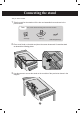
Connecting the stand - Only on some models. 1. T ake the parts for the stand out of the box and assemble them as shown in the picture below. Parts First, check that the following parts have been included. Screws (6) Stand (1) Cable management (1) 2. P lace a soft cloth on the table and place the screen downward. Connect the stand as shown in the following picture. 3. U se the screws to secure the stand on the rear side of the product as shown in the diagram.
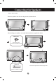
Connecting the Speakers - Only on some models. Mount the speakers onto the sets using screws as shown below. After installing your speakers, use cable holders and ties to organize the cables. Cable holder Remove the paper. * This feature is not available on all models. When the speaker is installed. Cable Ties *Connect the input terminal with the proper color. * This feature is not available on all models.
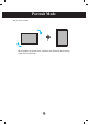
Portrait Mode - Only on some models. " When installing in portrait mode, rotate the sets clockwise when looking at the unit from the front.
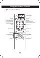
Using the Remote Control Remote Control Buttons • Power On/Off Button • I nput Select Button (See next page) • AV Button • ARC button Aspect Ratio Correction. Toggles through aspect ratio options. • Auto Button Automatic adjustment function (Operational for the analog signal only) • Sleep Button When watching AV, RGB PC,HDMI/DVI. The product will be automatically turned off after a certain period of time.
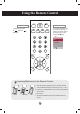
Using the Remote Control • AV Button • Input Select Button If you press the button once, the following Input Signal Window will appear. Select the signal type you want using the button. Toggles through video AV RGB PC HDMI/DVI Input AV RGB PC HDMI/DVI ▲▼ Inserting Batteries into the Remote Control AAA Type 1. Open the battery compartment cover on the back side and install the batteries matching correct polarity (+ with +,- with -). 2. Install two 1.5 V AAA batteries.
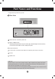
Part Names and Functions * Image shown may differ from your set. Rear View Power Connector : Connect the power cord RGB PC, HDMI/DVI Ports - HDMI Supports High Definition input and HDCP (High-bandwidth Digital Content Protection). Some devices require HDCP in order to display HD signals. RS-232C Serial Ports PC Sound Jack : Connect the audio cable to the *LINE OUT jack of the PC sound card. AV Ports Speaker Ports *LINE OUT A terminal used to connect to the speaker including a built-in amplifier (Amp).
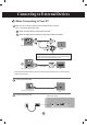
Connecting to External Devices When Connecting to Your PC Make sure the computer, product and the peripherals are turned off. Then, connect the signal input cable. A When connecting with the D-Sub signal input cable. B When connecting with the HDMI to DVI signal input cable (not included). A PC Rear side of the product. PC/MAC MAC Macintosh Adapter (not included) Use the standard Macintosh adapter since an incompatible adapter is available on the market(different signaling system).
Connecting to External Devices 1 Turn on power by pressing the power button on the product. Power button 2 Turn on the PC. Select an input signal. Press the INPUT button on the remote control to select the input signal. ▼▲ INPUT SET Or, press the SOURCE button on the back of the product. SOURCE A B ▼▲ AUTO/SET When connecting with a D-Sub signal input cable. • Select RGB PC : 15-pin D-Sub analog signal. When connecting with a HDMI to DVI signal input cable.
Connecting to External Devices VESA FDMI Wall Mounting This product supports a VESA FDMI compliant mounting interface. These mounts are purchased separately and not available from LG. Refer to the instructions included with wall mount for more info. Kensington Security Slot The Set is equipped with a Kensington Security System connector on the back panel. The cable and lock are available separately and are not sold by LG. For more info, visit http://www.kensington.
Connecting to External Devices Video Input Connect the video cable as shown below and then connect the power cord (see page 10). A Connecting with a BNC cable. •C onnect the input terminal with the proper color. Product Audio Cable (not included) BNC Cable (not included) VCR/DVD Receiver Select an input signal. Press the INPUT button on the remote control to select the input signal. INPUT ▼▲ SET Or, press the SOURCE button on the back of the product.
Connecting to External Devices HDMI Input (480p/576p/720p/1080i/1080p) - HDMI supports high definition input and HDCP (High-bandwidth Digital Content Protection). Some devices require HDCP in order to display HD signals. Connect the video/audio cable as shown below and then connect the power cord (see page 10).
Connecting to External Devices Watching AV Outputs - When using the AV input, you can connect the AV Out to other monitors. Product BNC Cable (not included) Audio Cable (not included) Video/TV Note • When multi-connecting in/out cascade format, no loss cables are recommended. We recommend using a cable distributor.
User Menus Screen Adjustment Options Power Button Power Indicator • Press this button to turn on the power. Press this button again to turn it off. • This Indicator lights up blue when the display operates normally(on mode). If the display is in sleep (Energy Saving) mode, this indicator color changes to amber. MENU Button • Use this button to show/hide the OSD (On Screen Display). OSD Select / Adjust Button • Use this button to select an icon or adjust the setting in the OSD.
User Menus Screen Adjustment Options AUTO/SET Button [For PC Analog signal] Auto in progress For optimal display change resolution to 1920 x 1080 [When 1920 x 1080 is selected] Auto in progress SOURCE Button SOURCE ▼▲ AUTO/SET - Toggles between inputs AV RGB PC HDMI/DVI Composite video, Separate video 15-pin D-Sub analog signal Digital signal Input AV RGB PC HDMI/DVI ▲▼ IR Receiver • This is where the unit receives signals from the remote control.
User Menus OSD Menu Icon Function Description Adjusts screen brightness, contrast and color. Picture Adjusts audio. Audio Adjusts the timer options. Time Option Information Note Adjusts the screen status. Adjust ID and checks Serial No. and SW version. OSD(On Screen Disp lay) The OSD function enables you to conveniently adjust the screen status with a graphic interface.
User Menus How to Adjust the OSD (On-Screen Display) Pops up the menu screen Move where you want to adjust Select a menu icon Move where you want to adjust Select a menu icon Adjust the status Save adjustment Exit from the menu screen. • Use the remote control to adjust the OSD. 1 Press the MENU button and the main menu of the OSD appears. 2 To navigate, use the 3 When you've highlighted the desired icon, press SET. 4 Use the 5 Accept the changes by pressing SET.
User Menus Adjusting Screen Color Picture Mode Picture Picture Mode Color Temperature Advanced Aspect Ratio Picture Reset Screen Vivid Standard Cinema Sport Game User1 User2 MENU Toggles between screen presets. • Vivid : Displays a sharp image. • Standard : This is the optimum viewing condition for general users. • Cinema : This mode optimizes video for watching movies. • Sport : This mode emphasizes dynamic video and primary colors (e.g. white, uniforms, grass, sky blue, etc.
User Menus Adjusting Screen Color Color Temperature Picture Picture Mode Color Temperature Advanced Aspect Ratio Picture Reset Screen Cool Medium Warm User MENU Color Settings • Cool : Slightly purple temperature. • Medium : Slightly blue temperature. • Warm : Slightly red temperature. • User : Selects user-defined settings. User Red Green Blue 0 0 0 MENU Red / Green / Blue Set your own color levels.
User Menus Adjusting Screen Color Advanced Picture Picture Mode Color Temperature Advanced Aspect Ratio Picture Reset Screen To set MENU • Gamma : Set your own gamma value. : -50/0/50 O n the monitor, high gamma values display whitish images and low gamma values display high contrast images. • Film Mode : (Function works in AV mode.) W hen watching a movie, this function adjusts screen settings to the best picture appearance. • Black Level : ( Function works in AV(NTSC), HDMI/DVI modes.
User Menus Adjusting Screen Color Aspect Ratio Selects the image size of the screen. Picture Picture Mode Color Temperature Advanced Aspect Ratio Picture Reset Screen 16:9 Original 4:3 14:9 Zoom1 Zoom2 MENU 16:9 Widescreen mode. Just Scan Displays the full signal data without cropping any of the image. Original The aspect ratio is not adjusted from the original. It is set by the program being watched. 4:3 Selects a 4:3 aspect ratio image.
User Menus Adjusting Screen Color Picture Reset Return Picture Mode, Color Temperature, Advanced, Aspect Ratio to the default settings. Picture Picture Mode Color Temperature Advanced Aspect Ratio Picture Reset Screen To set MENU Screen Adjust the screen video. Picture Picture Mode Color Temperature Advanced Aspect Ratio Picture Reset Screen Screen To set Auto Config. Manual Config. XGA Mode Reset To set MENU MENU • Auto Config. (RGB PC input only) : Adjusts the screen position, clock and phase.
User Menus Adjusting Audio Sound Mode The best sound quality will be selected automatically depending on the video type that you're currently watching. Audio Sound Mode Auto Volume Balance Speaker Clear Voice Standard Music Cinema Sport Game User MENU • Clear Voice : B y differentiating the human sound range from others, Clear Voice II improves voice quality. • Standard : Offers standard-quality sound. • Music : Optimizes sound for listening to music. • Cinema : Optimizes sound for watching movies.
User Menus Adjusting the Timer Time Sleep Time Auto Sleep Power On Delay Power Saving Off MENU Sleep Time The power is automatically turned off when the time set by a user has passed. 1) Press MENU and then use to select the Sleep Time menu. 2) Press and then use to set the hour (00 to 23). 3) Press and then use to set the minutes (00 to 59). Auto Sleep If Auto Sleep is active and there is no input signal, the set switches to off automatically after 10 minutes.
User Menus Adjusting the Timer Time Sleep Time Auto Sleep Power On Delay Power Saving To set MENU Power Saving Level Off Level 1 Level 2 Level 3 MENU Power Saving Adjusting the screen brightness helps you save energy. • Level: Total 4 screen brightness levels are provided.
User Menus Selecting Options Option Language Key Lock ISM Method Power Indicator DPM Select Tile Mode Factory Reset To set MENU Language To choose the language in which the control names are displayed. Key Lock Use to select On or Off. The monitor can be set so that it can only be used with the remote control. This feature can prevent unauthorized viewing. To lock OSD screen adjustment, set the Key Lock tab to the 'On' position.
User Menus Selecting Options •T o use this function you need to use multiple sets and be connected by an RGB cable by a distributor and RS-232C. Tile mode Option Language Key Lock ISM Method Power Indicator DPM Select Tile Mode Factory Reset Tile Mode H-Size V-Size H-Position V-Position Reset Tile ID Natural Off 0 0 <> <> To Set 1 Off It is used to enlarge the screen and also used with several products to view screen.
User Menus Selecting Options - Tile mode (product 1 ~ 9) : c(3) x r(3) column ID 1 ID 2 ID 3 ID 4 ID 5 ID 6 ID 7 ID 8 ID 9 row - Tile mode (product 1 ~ 2) : c(2) x r(1) column ID 2 ID 1 row - Tile mode (product 1 ~16) : c(4) x r(4) column ID 1 ID 2 ID 3 ID 4 ID 5 ID 6 ID 7 ID 8 ID 9 ID10 ID 11 ID 12 ID 13 ID 14 ID 15 ID 16 row 30
User Menus Selecting Options Tile mode Option Language Key Lock ISM Method Power Indicator DPM Select Tile Mode Factory Reset Tile Mode H-Size V-Size H-Position V-Position Reset Tile ID Natural Off 0 0 <> <> To Set 1 Off MENU Factory Reset • H-Size Adjusts the horizontal size of the screen taking into account the size of the bezel. • V-Size Adjusts the vertical size of the screen taking into account the size of the bezel. • H-Position Moves the screen position horizontally.
User Menus Adjust Set ID and Check Serial No. and SW Version. Information Set ID Serial No. SW Version MENU Set ID You can assign a unique Set ID NO (name assignment) to each product when several products are connected. Specify the number (01 H to 63 H) using and exit. Use the assigned Set ID to individually control each product using the Product Control Program. Serial No. This menu shows the serial number of the product. SW Version This menu shows the software version.
Troubleshooting No Image is Displayed ● Is the product power cord connected? • See if the power cord is properly connected to the outlet. ● Is the power indicator light on? • See if the power switch is turned on. • May need service. ●P ower is on, power indicator is blue but the screen appears extremely dark. • Adjust brightness and contrast again. • Backlight may need repair. ● The power indicator amber? • If the product is in power saving mode, move the mouse or press any key.
Troubleshooting The Screen Image Looks Abnormal. ● Is the screen position wrong? • D-Sub analog signal - Press "AUTO" on the remote control to automatically select the optimal screen status that fits the current mode. If adjustment is not satisfactory, use the OSD Position menu. • See if the video card resolution and frequency are supported by the product. If the frequency is out of range, set to the recommended resolution in the Control Panel "Display" Setting menu.
Troubleshooting The Audio Does Not Work. ● No sound? • See if the audio cable is connected properly. • Adjust the volume. • See if the sound is set properly. ● Sound is too dull. • Select the appropriate equalizer setting. ● Sound is too low. • Adjust the volume. Screen Color is Abnormal. ●S creen has poor color resolution (16 colors). • Set the number of colors to more than 24 bits (true color) Select Control Panel - Display - Settings - Color Table menu in Windows.
Specifications Product specifications can change without prior notice for product improvement. LCD Panel 106.73 cm (42.02 inch) TFT (Thin Film Transistor) LCD (Liquid Crystal Display) Panel 0.4845 mm (H) x 0.4845 (V) mm (Pixel Pitch) Power Rated Voltage Power Consumption Dimensions & Weight AC 100-240 V~ 50 / 60 Hz 2.2 A On Mode : 220 W Typ. Sleep Mode : ≤ 1 W (RGB) / 2 W (HDMI/DVI) Off Mode : ≤ 0.5 W [2] [1] H H W D W D [4] [3] H H Width x Height x Depth [1] 99.56 cm (39.
Specifications Product specifications can change without prior notice for product improvement. Video Signal Max. Resolution RGB : 1920 x 1080 @ 60 Hz HDMI/DVI : 1920 x 1080 @ 60 Hz - It may not be supported depending on the OS or video card type. Recommended Resolution RGB : 1920 x 1080 @ 60 Hz HDMI/DVI : 1920 x 1080 @ 60 Hz - It may not be supported depending on the OS or video card type.
Specifications PC Mode - Preset Mode Preset mode Horizontal Frequency (kHz) Vertical Frequency (Hz) Preset mode Horizontal Frequency (kHz) Vertical Frequency (Hz) 1 640 x 350 31.469 70.8 *11 1280 x 768 47.7 60 2 720 x 400 31.468 70.8 *12 1360 x 768 47.72 59.799 *3 640 x 480 31.469 59.94 *13 1366 x 768 47.7 60 4 640 x 480 37.5 75 *14 1280 x 1024 63.981 60.02 *5 800 x 600 37.879 60.317 15 1280 x 1024 79.98 75.02 6 800 x 600 46.875 75 *16 1680 x 1050 65.
RS-232C Controlling the Multiple Product Use this method to connect several products to a single PC. You can control several products at a time by connecting them to a single PC.
RS-232C Controlling the Multiple Product Command Reference List COMMAND1 COMMAND2 01. Power 02. Input Select 03. Aspect Ratio 04. Screen Mute 05. Volume Mute 06. Volume Control 07. Contrast 08. Brightness 09. Color 10. Tint 11. Sharpness 12. OSD Select 13. Remote Lock/ key Lock 14. Balance 15. Color Temperature 16. Abnormal state 17. ISM mode 18. Auto configuration 19. Key 20. Tile Mode 21. Tile H Position 22. Tile V Position 23. Tile H Size 24. Tile V Size 25. Tile ID Set 26.
RS-232C Controlling the Multiple Product COMMAND1 COMMAND2 41. Power Saving 42. Power Indicator 43. H Position 44. V Position 45. H Size 46. V Size 47. Serial no. 48. S/W Version 49.
RS-232C Controlling the Multiple Product Transmission / Receiving Protocol Transmission [Command1][Command2][ ][Set ID][ ][Data][Cr] * [Command 1]: First command. (k, j, m, d, f, x) * [Command 2]: Second command.(a to u) * [Set ID]: Set up the Set ID number of product. range : 01Hto63H. by setting '0', server can control all products. * In case of operating with more than 2 sets using set ID as '0' at the same time, it should not be checked the ack message.
RS-232C Controlling the Multiple Product Transmission / Receiving Protocol ▲ 01. Power(Command : a) To control Power On / Off of the Set. Transmission [k][a][ ][Set ID][ ][Data][Cr] Data 0 : Power Off 1 : Power On Acknowledgement [a][ ][Set ID][ ][OK][Data][x] ▲ To show the status of Power On / Off. Transmission [k][a][ ][Set ID][ ][FF][Cr] Acknowledgement [a][ ][Set ID][ ][OK][Data][x] Data 0 : Power Off 1 : Power On ▲ 02.
RS-232C Controlling the Multiple Product Transmission / Receiving Protocol ▲ 03. Aspect Ratio(Command : c) (Main picture format) To adjust the screen format. You can also adjust the screen format using the ARC (Aspect Ratio Control) button on remote control or in the Screen menu.
RS-232C Controlling the Multiple Product Transmission / Receiving Protocol ▲ 05. Volume Mute(Command : e) To control On/Off of the Volume Mute. Transmission [k][e][ ][Set ID][ ][Data][Cr] Data 0 : Volume Mute On (Volume Off) 1 : Volume Mute Off (Volume On) Acknowledgement [e][ ][Set ID][ ][OK][Data][x] Data 0 : Volume Mute On (Volume Off) 1 : Volume Mute Off (Volume On) ▲ 06. Volume Control(Command : f) To adjust Volume .
RS-232C Controlling the Multiple Product Transmission / Receiving Protocol ▲ 07. Contrast(Command : g) To adjust screen contrast. You can also adjust the contrast in the Picture menu. Transmission [k][g][ ][Set ID][ ][Data][Cr] Data Min : 00H to Max : 64H • Refer to ‘Real data mapping’ as shown below. Acknowledgement [g][ ][Set ID][ ][OK][Data][x] * Real data mapping 0 : Step 0 : A : Step 10 : F : Step 15 10 : Step 16 : 64 : Step 100 ▲ 08. Brightness(Command : h) To adjust screen brightness.
RS-232C Controlling the Multiple Product Transmission / Receiving Protocol ▲ 09. Color(Command : i) (Video Timing only) To adjust the screen color. You can also adjust the color in the Picture menu. Transmission [k][i][ ][Set ID][ ][Data][Cr] Data Min : 00H to Max : 64H (Hexadecimal code) • Refer to ‘Real data mapping’ page A 8. Acknowledgement [i][ ][Set ID][ ][OK][Data][x] Data Min : 00H to Max : 64H ▲ 10. Tint(Command : j) (Video Timing only) To adjust the screen tint.
Controlling the Multiple Product RS-232C Transmission / Receiving Protocol ▲ 11. Sharpness(Command : k) (Video Timing only) To adjust the screen Sharpness. You can also adjust the sharpness in the Picture menu. Transmission [k][k][ ][Set ID][ ][Data][Cr] Data Min : 00H to Max : 64H (Hexadecimal code) • Refer to ‘Real data mapping’ page A 8. Acknowledgement [k][ ][Set ID][ ][OK][Data][x] Data Min : 00H to Max : 64H ▲ 12. OSD Select(Command : l) To control OSD on/off to the set.
RS-232C Controlling the Multiple Product Transmission / Receiving Protocol ▲ 14 Balance(Command : t) To adjust the sound balance. Transmission [k][t][ ][Set ID][ ][Data][Cr] Data Min : 00H to Max : 64H (Hexadecimal code) • Refer to ‘Real data mapping’ page A 8. Acknowledgement [t][ ][Set ID][ ][OK][Data][x] Data Min : 00H to Max : 64H * Balance : L50 to R50 ▲ 15. Color Temperature (Command : u) To adjust the screen color temperature.
RS-232C Controlling the Multiple Product Transmission / Receiving Protocol ▲ 16. Abnormal state (Command : z) Abnormal State : Used to Read the power off status when Stand-by mode.
RS-232C Controlling the Multiple Product Transmission / Receiving Protocol ▲ 18. Auto Configure(Command: j u) To adjust picture position and minimize image shaking automatically. it works only in RGB(PC) mode. Transmission [j][u][ ][Set ID][ ][Data][Cr] Data 1 : To set Acknowledgement [u][ ][Set ID][ ][OK][Data][x] ▲ 19. Key(Command : m c) To send IR remote key code. Transmission [m][c][ ][Set ID][ ][Data][Cr] Data Key code : Refer to page A 34.
Controlling the Multiple Product RS-232C Transmission / Receiving Protocol ▲ 20. Tile Mode(Command : d d) Change a Tile Mode. Transmission [d][d][][Set ID][][Data][x] Data 00 or 11 12 13 14 ... 55 Description Tile mode is off. 1 x 2 mode(column x row) 1 x 3 mode 1 x 4 mode ... 5 x 5 mode * The data can not be set to 0X or X0 except 00.
RS-232C Controlling the Multiple Product Transmission / Receiving Protocol ▲ 21. Tile H Position(Command : d e) To set the Horizontal position. Transmission [d][e][][Set ID][][Data][x] Data Min : 00H to Max : 64H • Refer to ‘Real data mapping’ page A 8. Acknowledgement [e][][Set ID][][OK/NG][Data][x] ▲ 22. Tile V Position(Command : d f) To set the Vertical position. Transmission [d][f][][Set ID][][Data][x] Data Min : 00H to Max : 64H • Refer to ‘Real data mapping’ page A 8.
RS-232C Controlling the Multiple Product Transmission / Receiving Protocol ▲ 23. Tile H Size(Command : d g) To set the Horizontal size. Transmission [d][g][][Set ID][][Data][x] Data Min : 00H to Max : 64H • Refer to ‘Real data mapping’ page A 8. Acknowledgement [g][][Set ID][][OK/NG][Data][x] ▲ 24. Tile V Size(Command : d h) To set the Vertical size. Transmission [d][h][][Set ID][][Data][x] Data Min : 00H to Max : 64H • Refer to ‘Real data mapping’ page A 8.
Controlling the Multiple Product RS-232C Transmission / Receiving Protocol ▲ 25. Tile ID Set(Command : d i) To assign the Tile ID for Tiling function . Transmission [d][i][][Set ID][][Data][x] Data Min : 00H to Max : 19H (Hexadecimal code) Acknowledgement [i][][Set ID][][OK/NG][Data][x] ▲ 26 Natural Mode (In Tile mode) (Command : d j) To assign the Tile Natural mode for Tiling function .
RS-232C Controlling the Multiple Product Transmission / Receiving Protocol ▲ 28. Sound Mode (Command : d y ) To adjust the Sound mode. Transmission [d][y][][Set ID][][Data][x] Data Structure Data(Hex) 00 01 02 03 04 05 06 Mode Clear Voice Standard Music Cinema sport Game User Acknowledgement [y][][Set ID][][OK/NG][Data][x] ▲ 29. Fan Fault check (Command : d w ) To check the Fan fault of the TV. Transmission [d][w][][Set ID][][Data][x] * The data is always FF(in Hex).
RS-232C Controlling the Multiple Product Transmission / Receiving Protocol ▲ 30. Elapsed time return(Command : d l) To read the elapsed time. Transmission [d][l][][Set ID][][Data][x] * The data is always FF(in Hex). Acknowledgement [l][][Set ID][][OK/NG][Data][x] * The data means used hours. (Hexadecimal code) ▲ 31. Temperature value (Command : d n) To read the inside temperature value. Transmission [d][n][][Set ID][][Data][x] * The data is always FF(in Hex).
RS-232C Controlling the Multiple Product Transmission / Receiving Protocol ▲ 33. Auto volume (Command : d u) Automatically adjust the volume level. Transmission [d][u][][Set ID][][Data][x] Data 0 : Off 1 : On Acknowledgement [u][][Set ID][][OK/NG][Data][x] ▲ 34. Speaker (Command : d v) Turn the speaker on or off.
RS-232C Controlling the Multiple Product Transmission / Receiving Protocol ▲ 35. Sleep Time (Command : f f) Set Sleep Time. Transmission [f][f][][Set ID][][Data][Cr] Data 0 : Off 1 : 10 2 : 20 3 : 30 4 : 60 5 : 90 6 : 120 7 : 180 8 : 240 (Orderly) Acknowledgement [f][][Set ID][][OK/NG][Data][x] ▲ 36. Auto Sleep (Command : f g) Set Auto Sleep.
RS-232C Controlling the Multiple Product Transmission / Receiving Protocol ▲ 37. Power On Delay (Command : f h) Set the schedule delay when the power is turned on (Unit: second). Transmission [f][h][][Set ID][][Data][Cr] Data : 00H to 64H (Data value) • Refer to ‘Real data mapping’ page A 8. Acknowledgement [h][][Set ID][][OK/NG][Data][x] ▲ 38. Language (Command : f i) Set the OSD language.
RS-232C Controlling the Multiple Product Transmission / Receiving Protocol ▲ 39. DPM Select (Command : f j) Set the DPM (Display Power Management) function. Transmission [f][j][][Set ID][][Data][Cr] Data 0 : Off 1: On Acknowledgement [j][][Set ID][][OK/NG][Data][x] ▲ 40. Reset (Command : f k) Execute the Picture, Screen and Factory Reset functions.
RS-232C Controlling the Multiple Product Transmission / Receiving Protocol ▲ 41. Power saving(Command : f I) To set the Power saving mode. Transmission [f][I][][Set ID][][Data][Cr] Data 0 : Off 1: (static level 1) 2: (static level 2) 3: (static level 3) Acknowledgement [I][][Set ID][][OK/NG][Data][x] ▲ 42. Power Indicator (Command : f o) To set the LED for Power Indicator Transmission [f][o][][Set ID][][Data][Cr] Data 0 : Off 1: On Acknowledgement [o][][Set ID][][OK/NG][Data][x] ▲ 43.
RS-232C Controlling the Multiple Product Transmission / Receiving Protocol ▲ 44. V Position (Command : f r) To set the Horizontal position Transmission [f][r][][Set ID][][Data][Cr] * The data range is from 00 to 64(in Hex) • Refer to ‘Real data mapping’ page A 8. Acknowledgement [r][][Set ID][][OK/NG][Data][x] ▲ 45. H Size (Command : f s) To set the Horizontal size. Transmission [f][s][][Set ID][][Data][Cr] * The data range is from 00 to 64(in Hex) • Refer to ‘Real data mapping’ page A 8.
RS-232C Controlling the Multiple Product Transmission / Receiving Protocol ▲ 46. V Size (Command : f t) To set the Vertical size Transmission [f][t][][Set ID][][Data][Cr] * The data range is from 00 to 64(in Hex) • Refer to ‘Real data mapping’ page A 8. Acknowledgement [t][][Set ID][][OK/NG][Data][x] * V Size Real Data Mapping [Data1] 0x00: Step 0 0x0A: Step 10 0x14: Step 20 0x1E: Step 30 0x28: Step 40 0x32: Step 50 0x3C: Step 60 0x46: Step 70 0x50: Step 80 0x5A: Step 90 0x64: Step 100 ▲ 47.
RS-232C Controlling the Multiple Product Transmission / Receiving Protocol ▲ 48. S/W Version (Command : f z) Check the software version. Transmission [f][z][][Set ID][][Data][Cr] Data FFH : Read Acknowledgement [z][][Set ID][][OK/NG][Data][x] ▲ 49. Input Select (Command : x b) To select input source for the Set.
Controlling IR theCodes Multiple Product RS-232C ▲ How to connect Connect your wired remote control to Remote Control port on the Product. Remote Control IR Code ▲ Output waveform single pulse, modulated with 37.
Controlling IR theCodes Multiple Product RS-232C Code(Hex) Function Note ▲ R/C Button 01 ▼ R/C Button 02 VOL( ) R/C Button 03 VOL( ▲ R/C Button 08 POWER ON/OFF R/C Button (Power On / Off) C4 POWER ON Discrete IR Code (Only Power On) C5 POWER OFF Discrete IR Code (Only Power Off) 09 MUTE R/C Button 98 AV R/C Button 0B INPUT R/C Button 0E SLEEP R/C Button 43 MENU R/C Button 5B EXIT R/C Button 6E PSM R/C Button 44 SET R/C Button 10 Number Key 0 R/C Button 1
Make sure to read the Safety Precautions before using the product. Keep the Owner's Manual(CD) in an accessible place for future reference. The model and serial number of the SET is located on the back and one side of the SET. Record it below should you ever need service. MODEL SERIAL ENERGY STAR is a set of power-saving guidelines issued by the U.S.Environmental Protection Agency(EPA). As an ENERGY STAR Partner LGE U. S. A.,Inc.