ENGLISH OWNER’S MANUAL LCD MONITOR Please read this manual carefully before operating your set and retain it for future reference. LCD MONITOR MODELS W2363D www.lg.
Important Precautions This unit has been engineered and manufactured to ensure your personal safety, however improper use may result in potential electrical shock or fire hazards. In order to allow the proper operation of all safeguards incorporated in this display, observe the following basic rules for its installation, use, and servicing. On Safety Use only the power cord supplied with the unit.
Important Precautions On Installation Do not allow anything to rest upon or roll over the power cord, and do not place the display where the power cord is subject to damage. Do not use this display near water such as near a bathtub, washbowl, kitchen sink, laundry tub, in a wet basement, or near a swimming pool. Displays are provided with ventilation openings in the cabinet to allow the release of heat generated during operation.
Important Precautions On Cleaning Unplug the display before cleaning the face of the display screen. Use a slightly damp (not wet) cloth. Do not use an aerosol directly on the display screen because over-spraying may cause electrical shock. When cleaning the product, unplug the power cord and scrub gently with a soft cloth to prevent scratching. Do not clean with a wet cloth or spray water or other liquids directly onto the product. An electric shock may occur.
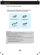
Accessories Thank for selecting LGE products Please make sure the following items are included with your monitor. If any items are missing, contact your dealer. Power Cord (Depending on the country) OWNER'S MANUAL/Cards DVI-D Signal Cable (Dual) Audio Cable IMPORTANT Actual accessories may look different from those shown here. User must use shielded signal interface cables (DVI-D cable) with ferrite cores to maintain standard compliance for the product. Requirements for 3D (3 Dimensional) imagery 1.
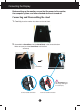
Connecting the Display Before setting up the monitor, ensure that the power to the monitor, the computer system, and other attached devices is turned off. Connecting and Disassembling the stand 1. Carefully place the monitor face down on the soft cloth. 2. Assemble the Stand Base into the Stand Body in the correct direction. Make sure you push the Stand Base until the end. Stand Body Stand Base The Stand Base may fall and get damaged or cause injury.
Connecting the Display 3. Turn the screw to the right to fix the Stand Body to the Stand Base. Screw Turn the screw by using the screw handle. 4. Then fold the screw handle flat. 5. Once assembly is complete the monitor up carefully and position for use. 6. To disconnect the Stand Base from the Stand Body, simply unfold the screw handle and turn "counter-clockwise" to loosen the screw and disconnect the Stand Base from its body. IMPORTANT This picture depicts the general model of connection.
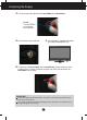
Connecting the Display Before setting up the monitor, ensure that the power to the monitor, the computer system, and other attached devices is turned off. Positioning your display After installation, adjust the angle as shown below. 1. Adjust the position of the panel in various ways for maximum comfort. Tilt Range: -5˚ to 15˚ 15 -5 Do not touch or press the screen when adjusting the angle of the monitor.
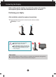
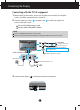
Connecting the Display Connecting with the PC/AV equipment 1. Before setting up the monitor, ensure that the power to the monitor, the computer system, and other attached devices is turned off. 2. Connect signal input cable 1 and power cord 2 in order, then tighten the screws of the signal cable. A Connect DVI-D (Digital signal) Cable B Connect HDMI Cable (HDMI1, HDMI2) NOTE This is a simplified representation of the rear view.
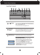
Control Panel Functions Front Panel Controls Button Use this button to enter THRU MODE, SRS TRUSURROUND HD, ARC or AUTO BRIGHT menus. For more information, refer to page 13 to 14. SOURCE Button When two input signals are connected, you can select the input signal (DVI-D/HDMI1/HDMI2) you want. When only one signal is connected, it is automatically detected. MENU Button Use this button to enter or exit the On Screen Display.
Control Panel Functions Buttons Use these buttons to select or adjust functions in the On Screen Display. SET Button This button is used to enter a selection in the On Screen Display. TRU-LIGHT Button You can select GAME, MOVIE or MUSIC by using this button and the LED light shape will change according to each mode. When you select OFF, the LED light will be turned off. TRU-LIGHT GAME MOVIE MUSIC OFF Power Button Use this button to turn the display on or off.
On Screen Display (OSD) Control Adjustment Screen Adjustment Making adjustments to the image size, position and operating parameters of the display is quick and easy with the On Screen Display Control system. A short example is given below to familiarize you with the use of the controls. The following section is an outline of the available adjustments and selections you can make using the OSD.
On Screen Display (OSD) Control Adjustment The following table indicates all the On Screen Display control, adjustment, and setting menus. 3D mode DVI-D HDMI Main menu G-MODE Sub-menu Supported input DVI-D THRU MODE : 3D mode output : DVI-D(Digital signal) input : HDMI input Description Use Frame-Buffer to prevent picture delay. HDMI SRS TRUSURROUND HD 3D mode DVI-D HDMI Use 3D surround for live sound effect. ARC 3D mode DVI-D HDMI Use aspect ratio control.
On Screen Display(OSD) Selection and Adjustment The OSD screen will appear when you press the of the monitor. Menu Name G-MODE button on the front MENU Icons : Move SET Sub-menu Name Main menu THRU MODE THRU MODE Sub menu THRU MODE G-MODE ON : Save & Exit : Enter ON Description ON This prevents the response speed of the display from delaying by disabling the frame buffer memory. Set this for the game mode. OFF This shows the optimized screen by using the frame buffer memory.
On Screen Display(OSD) Selection and Adjustment Main menu ARC G-MODE ARC Sub menu FULL Description 1:1 The picture will be displayed depends on Input resolution.No Scaling. If 640 x 480 resolution input, the picture will just display 640 x 480 size even though the 1920 x 1080 size panel. ORIGINAL The picture will be displayed with input resolution ratio scaling. If 640 x 480 resolution input, the picture will keep at 4:3 ratio scaling. FULL The picture will be displayed with Full size.
On Screen Display(OSD) Selection and Adjustment You were introduced to the procedure of selecting and adjusting an item using the OSD system. Listed below are the icons, icon names, and icon descriptions of the all items shown on the Menu. Press the MENU Button, then the main menu of the OSD appears.
On Screen Display(OSD) Selection and Adjustment Main menu Sub menu Description PICTURE DVI-D input BRIGHTNESS To adjust the brightness of the screen. HDMI input CONTRAST To adjust the contrast of the screen. GAMMA Set your own gamma value: -50 / 0 / 50 On the monitor, high gamma values display whitish images and low gamma values display blackish images. BLACK LEVEL You can set the off set level. If you select 'HIGH', the screen will be bright and if you select ‘LOW’, the screen will be dark.
On Screen Display(OSD) Selection and Adjustment Main menu Sub menu Description COLOR DVI-D input PRESET • sRGB: Set the screen color to fit the sRGB standard color specification. • 6500K: Slightly reddish white. • 9300K: Slightly bluish white. RED Set your own red color levels. GREEN Set your own green color levels. BLUE Set your own blue color levels. HUE Set your own hue levels. SATURATION Set your own saturation levels.
On Screen Display(OSD) Selection and Adjustment Main menu Sub menu Description SHARPNESS To adjust the sharpness of the screens cpmtemt.
On Screen Display(OSD) Selection and Adjustment Main menu Sub menu Description SETUP DVI-D input LANGUAGE To choose the language in which the control names are displayed. To adjust the volume of headphone/Earphone. VOLUME OVERSCAN Removes noise that may occur at the edges of an image when HDMI is connected to an external device. When ON is selected, the image size is reduced to prevent noise. When OFF is selected, the original image size is maintained regardless of noise.
Troubleshooting Check the following before calling for service. No image appears ● Is the power cord of the • Check and see if the power cord is connected properly to the power outlet. display connected? ● Is the power indicator light on? • Press the Power button. ● Is the power indicator blinking? • If the display is in power saving mode, try moving the mouse or pressing any key on the keyboard to bring up the screen. • Try to turn on the PC.
Troubleshooting Display image is incorrect ● The screen color is mono or abnormal. • Check if the signal cable is properly connected and use a screwdriver to fasten if necessary. • Make sure the video card is properly inserted in the slot. • Set the color setting higher than 24 bits (true color) at Control Panel - Settings. ● The screen blinks. • Check if the screen is set to interlace mode and if yes, change it to the recommend resolution.
Specifications Display 58.4 cm (23.0 inch) Flat Panel Active matrix-TFT LCD Anti-Glare coating Visible diagonal size: 58.4 cm 0.266 mm x 0.266 mm (Pixel Pitch) Sync Input Horizontal Freq. Vertical Freq.
Specifications Preset Modes (Resolution) - DVI-D(Digital) INPUT Display Modes (Resolution) Horizontal Freq. (kHz) 640 x 350 720 x 400 640 x 480 640 x 480 800 x 600 800 x 600 1024 x 768 1024 x 768 1152 x 864 1280 x 1024 1280 x 1024 1680 x 1050 1680 x 1050 1920 x 1080 1920 x 1080 1920 x 1080 1920 x 1080 31.469 31.468 31.469 37.500 37.879 46.875 48.363 60.123 67.500 63.981 79.976 64.674 65.290 67.500 113.721 125.668 137.860 1 2 3 4 5 6 7 8 9 10 11 12 13 *14 **15 **16 **17 Vertical Freq.
Installing the Wall mount plate This monitor satisfies the specifications of the Wall mount plate or the interchange device. 1. Carefully place the monitor face down on the soft cloth. 2. To disconnect the Stand Base from the Stand Body, simply unfold the screw handle and turn "counter-clockwise" to loosen the screw and disconnect the Stand Base from its body. 3. Pull out the Stand Base to remove.
Installing the Wall mount plate 4. Install the Wall mount plate. Wall mount plate(Separate purchase) This is stand-type or wall mount type and is connectable with Wall mount plate. Please refer to the installation guide for more details, which is provided when Wall mount plate is purchased. Wall Mount pad Kensington Security Slot Connected to a locking cable that can be purchased separately at most computer stores. Hole spacing : 100 mm x 100 mm.
Make sure to read the Important Precautions before using the product. Keep the User’s Guide(CD) in an accessible place for furture reference. The model and serial number of the SET is located on the back and one side of the SET. Record it below should you ever need service.