User Guide for the LTD-BK1110 Product: LTE_WCDMA Wireless Modem Model name: LTD-BK1110 Table of Contents 1. Overview 2. Major features 3. Interface 4. Electrical specifications 5. RF specifications 6. Mechanical specifications 7. General specifications 8. Connectors 9. RFx information 10. Approbation FCC Copyright ⓒ. 2017. All Rights Reserved.
1. Overview The LTD-BK1110 is a personal mobile communication device that incorporates the latest compact radio technology, including smaller and lighter components and support for WCDMA(850/1900MHz) bands and LTE(700/850/1700/1900/2700 MHz). This device acts as the vehicle’s telematics system and connects to WCDMA (HSPA+) and LTE wireless networks and wireless modules to allow voice and data communication. Furthermore, this device can operate on land and water as well as other similar areas.
2. Major features Dimensions Weight Mechanical Interface 34 x 40 x 3.5 mm (L x W x T) (Tolerance – width, length : TBD) TBD g (max) USB, general purpose I/O pins Temperature* Operation: -20 ℃ - +70 ℃ Storage: -40 ℃ - +85 ℃ Main chipset MDM9628 Memory 4Gb(NAND) / 1Gb(SDRAM) Standard WCDMA (HSPA+) - DL Speed : 14.4 Mbps - UL Speed : 5.76 Mbps LTE - DL Speed : 150 Mbps - UL Speed : 50 Mbps Technology Band WCDMA B2, B5 LTE B2, B4, B5, B12(17), B7 Power WCDMA : Typ.
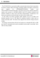
3. Interface 3.1 LGA Pad Layout (Top View) Figure 1. LGA Pin map Copyright ⓒ. 2017. All Rights Reserved.
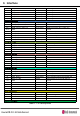
3. Interface 3.2 Pin description PAD.
3.
3.
3.
3.
3.
3.
3. Interface 3.3 USB This device supports universal serial bus (USB) connections for high-speed data communication. The relevant hardware satisfies the USB 2.0 specifications and supports maximum communications speeds of 480 Mbps Pin NO. Signal Name Pin I/O (Modem host) Function Description M1 USB_D+ IO USB Differential data line (+) N2 USB_D- IO USB Differential data line (-) K1 USB_VBUS I USB Power Supply Table 2. USB Pin descriptions Copyright ⓒ. 2017. All Rights Reserved.
3. Interface 3.4 Audio This module includes a PCM interface. The pull-up and pull-down resistors attached to these pin must provide more than 50 Kohm of resistance. Pin NO. Pin I/O (Modem host) Signal Name Function Description W1 PCM_SYNC I PCM Interface sync X2 PCM_CLK I PCM Interface clock Y1 PCM_TXD O PCM Interface digital audio data out Y3 PCM_RXD I PCM Interface digital audio data in Table 3. PCM Pin descriptions 3.5 User interface Pin No.
4. Electrical specifications 4.1 Power supply specifications The host system provides the power supply (V_BATT)DC 4 V, 2.5 A to the device. The internal power supply module manages the power supplied to the integral circuits and maintains constant voltages. This module also controls each power block to minimize power consumption. In particular, the PAM (power amplifier module) consumes a lot of power, so it receives a direct power supply of 4 V from the V_BATT.
4. Electrical specifications 4.2 Logic level specifications 4.2.1 Digital logic level specifications Signal Name Type BOOT_OK RESET_IN MSG 168H_END ACC_ON_SLEEP O I O O I Low Min 0 -0.3 0 0 0 High Max 0.45 0.63 0.45 0.45 0.63 Min 1.35 1.17 1.35 1.35 1.17 Table 6. Digital logic level specifications Copyright ⓒ. 2017. All Rights Reserved. Max 1.8 1.8 1.8 1.8 1.
5. RF specifications 5.1 WCDMA 5.1.1 Receiver .- Bandwidth : 5MHz .- Frequency : 869MHz – 894MHz (B5), 1930MHz – 1990MHz (B2) .- RF to Baseband Direct conversion (Zero IF) .- Modulation method : QPSK, 16QAM .- Sensitivity : ≤-104dBm (BER = Under 0.1%) 5.1.2 Transmitter .- Frequency: 824MHz – 849MHz (B5), 1850MHz – 1910MHz (B2) .- Maximum RF Output : Power class3 , 20.3dBm ~ 25.7dBm .- Modulation method : QPSK .- Baseband to RF Direct conversion (Zero IF) 5.2 LTE 5.2.1 Receiver .
5. RF specifications 5.2.2 Transmitter .- Frequency: B2 (1850 MHz – 1910 MHz), B4 (1710 MHz – 1755 MHz), B5 (824 MHz – 849 MHz), B7 (2500 MHz – 2570 MHz), B12&B17(699 MHz – 716 MHz) .- Maximum RF Output : Power class3 , 20.3dBm ~ 25.7dBm .- Modulation method : QPSK and 16QAM .- Baseband to RF Direct conversion (Zero IF) Copyright ⓒ. 2017. All Rights Reserved.
6. Mechanical specifications 6.1 Environment specifications .- Storage temp.: -40 ℃ - +85 ℃ .- Operating temp.: -20 ℃ - +70 ℃ (-20 ℃ - +70 ℃ : 3GPP specifications are satisfied -30 ℃ - -20 ℃, +70 ℃ - +80 ℃ : May cause performance degradation) .- Operating humidity: 80% (60℃) relative humidity Copyright ⓒ. 2017. All Rights Reserved.
6. Mechanical specifications 6.1 Mechanical dimensions Dimensions 34 x 40.0 x 3.5 mm (L x W x T) (Tolerance – width, length : TBD) Weight TBD grams(max.) Table 7. Mechanical specification Figure 2. Mechanical dimension Copyright ⓒ. 2017. All Rights Reserved.
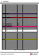
7. General specifications 7.1 WCDMA B5 electrical specifications TEST ITEM 1 Spec. Test Temperature Test Freq uency Normal, Temp L, Te mp H Normal, Temp L, Te mp H Low, Mid, High Low, Mid, High CHANNEL 4357 4400 4458 PASS PASS PASS PASS PASS PASS Maximum Output Power 20.3~25.
7. General specifications 7.2 WCDMA B2 electrical specifications Test Temperature Test Freq uency Normal, Temp L, Te mp H Normal, Temp L, Te mp H Low, Mid, High Low, Mid, High TEST ITEM Spec. 1 Maximum Output Power 20.3~25.
7. General specifications 7.3 LTE B2 electrical specifications TX Channel 시험 항목 Spec. Test Temperature Frequency 1 Maximum Output Power(class 3) 20.3~25.7dBm Normal, Temp L, Temp H 2 Minimum Output Power -39dBm ↓ 3 Frequency Error 4 Error Vector Magnitude(EVM) 18650 18900 19150 Low, Mid, High PASS PASS PASS Normal, Temp L, Temp H Low, Mid, High PASS PASS PASS ±0.1ppm Normal, Temp L, Temp H Low, Mid, High PASS PASS PASS 12.
7. General specifications 7.4 LTE B4 electrical specifications TX Channel 시험 항목 Spec. Test Temperature Frequency 1 Maximum Output Power(class 3) 20.3~25.7dBm Normal, Temp L, Temp H 2 Minimum Output Power -39dBm ↓ 3 Frequency Error 4 Error Vector Magnitude(EVM) 20000 20175 20350 Low, Mid, High PASS PASS PASS Normal, Temp L, Temp H Low, Mid, High PASS PASS PASS ±0.1ppm Normal, Temp L, Temp H Low, Mid, High PASS PASS PASS 12.
7. General specifications 7.5 LTE B5 electrical specifications TX Channel 시험 항목 Spec. Test Temperature Frequency 1 Maximum Output Power(class 3) 20.3~25.7dBm Normal, Temp L, Temp H 2 Minimum Output Power -39dBm ↓ 3 Frequency Error 4 Error Vector Magnitude(EVM) 20450 20525 20600 Low, Mid, High PASS PASS PASS Normal, Temp L, Temp H Low, Mid, High PASS PASS PASS ±0.1ppm Normal, Temp L, Temp H Low, Mid, High PASS PASS PASS 12.
7. General specifications 7.6 LTE B7 electrical specifications TX Channel 시험 항목 Spec. Test Temperature Frequency 1 Maximum Output Power(class 3) 20.3~25.7dBm Normal, Temp L, Temp H 2 Minimum Output Power -39dBm ↓ 3 Frequency Error 4 Error Vector Magnitude(EVM) 23780 23790 23800 Low, Mid, High PASS PASS PASS Normal, Temp L, Temp H Low, Mid, High PASS PASS PASS ±0.1ppm Normal, Temp L, Temp H Low, Mid, High PASS PASS PASS 12.
7. General specifications 7.7 LTE B12/17 electrical specifications TX Channel 시험 항목 Spec. Test Temperature Frequency 1 Maximum Output Power(class 3) 20.3~25.7dBm Normal, Temp L, Temp H 2 Minimum Output Power -39dBm ↓ 3 Frequency Error 4 Error Vector Magnitude(EVM) 23780 23790 23800 Low, Mid, High PASS PASS PASS Normal, Temp L, Temp H Low, Mid, High PASS PASS PASS ±0.1ppm Normal, Temp L, Temp H Low, Mid, High PASS PASS PASS 12.
8. RFx information The strength of the RF field produced by the wireless module or modules embedded in the TCU is well within all international RF exposure limits known at this time. Because the wireless modules embedded in the TCU emit less than the maximum amount of energy permitted in radio frequency safety standards and recommendations, the manufacturer believes these modules are safe for use. Regardless of the power levels, care should be taken to minimize human contact during normal operation.
9. Approbation FCC This module complies with FCC/IC rules. FCC : Part 22, Part 24, Part 27 ISED : RSS-130, RSS-132, RSS-133, RSS-139, RSS-199 Furthermore, this device complies with FCC radiation exposure limits set forth for uncontrolled environments. This module must be installed and operated with minimum distance of 20 cm between the radiating element and the user. This module must not be co-located with any other transmitters or antennas.