UUGGwGXWGG{ SGhGY[SGYWYXGGZaXYGwt 10 INSTALLATION INSTALLATION Before Installing Installation Overview Please read the following installation instructions first after purchasing this product or transporting it to another location. The images in this guide may be different from the actual components and accessories, which are subject to change by the manufacturer without prior notice for product improvement purposes.
UUGGwGXXGG{ SGhGY[SGYWYXGGZaXYGwt INSTALLATION 11 Tools Needed a 4-Wire cord or 3-Wire cord (UL approved 40 or 50 AMP) b Strain relief (For conduit installations only) • Observe all governing codes and ordinances. • Have the installer show you the location of the circuit breaker or fuse. Mark it for easy reference.
UUGGwGXYGG{ SGhGY[SGYWYXGGZaXYGwt 12 INSTALLATION NOTE • Your range is heavy and can be installed on soft floor coverings such as cushioned vinyl or carpeting. Use care when moving the range on this type of flooring. Use a belt when moving the range to prevent damaging the floor. Or slide the range onto cardboard or plywood to avoid damaging the floor covering. Flooring CAUTION • Use an insulated pad or 1/4 in. (0.
UUGGwGXZGG{ SGhGY[SGYWYXGGZaXYGwt INSTALLATION 13 Dimensions and Clearances Dimensions ENGLISH - Dimensions LSES6338 A Width 29 7/8" (758.8 mm) B Height 37 1/4" (946 mm) C Depth (Includes Door Handle) D Height (Excludes Vent Trim) E Depth (Includes only the product body that is loaded into the cabinet. Excludes door, drawer, and handles) F Depth (Excludes Door Handle) G Depth when drawer is fully opened 36 1/16" (916.
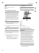
UUGGwGX[GG{ SGhGY[SGYWYXGGZaXYGwt 14 INSTALLATION Clearances a Acceptable electrical outlet area b Normal counter top depth c Counter top height d Cabinet e Wall f Center A (Cabinet opening) = 30" (76.2 cm) For U.S.A = 30" (76.2 cm) ~ 31" (78.
UUGGwGX\GG{ SGhGY[SGYWYXGGZaXYGwt INSTALLATION 15 a 30" (76.2 cm) minimum clearance between the top of the cooking surface and the bottom of an b 15" (38.1 cm) minimum between countertop and adjacent cabinet bottom. NOTE • Important – Save for the use of the local electrical inspector. • For installation in Canada, a free-standing range is not to be installed closer than 15/32" (12 mm) from any adjacent surface.
UUGGwGX]GG{ SGhGY[SGYWYXGGZaXYGwt 16 INSTALLATION Specified Power Cord Kit Rating Case 1 • Voltage: 120/240 volts (3-wire) • Range rating: 8,750 W - 16,500 W Connecting the Power Cord / Conduit The rear access cover a must be removed. Loosen the two screws with a screwdriver. The terminal block will then be accessible.
UUGGwGX^GG{ SGhGY[SGYWYXGGZaXYGwt INSTALLATION 17 f Ring 5 g Body i Conduit CAUTION • Do not remove the ground strap connections. 3-Wire Connection: Power Cord WARNING • The middle (neutral or ground) wire, which is white, of a 3-wire power cord or a 3-wire conduit has to be connected to the middle post of the main terminal block. The remaining two wires of the power cord or conduit have to be connected to the outside posts of the main terminal connection block.
UUGGwGX_GG{ SGhGY[SGYWYXGGZaXYGwt 18 INSTALLATION 2 Insert the power cord through the strain relief and tighten it. CAUTION • Do not install the power cord without a strain relief. 3 4 5 6 Remove the lower 3 screws from the terminal block and retain them. Remove the ground screw and bend the end of the ground strap up so the slot is over the hole of the center screw removed in step 3.
UUGGwGX`GG{ SGhGY[SGYWYXGGZaXYGwt INSTALLATION 19 2 4 Insert the two side bare wire ends into the lower left and the lower right terminal block openings. Tighten the 3 screws securely into the terminal block. (approximately 35 - 50 IN-LB) Conduit Installations CAUTION • Do not install the conduit without a strain relief. 1 Remove the cord/conduit connection plate from the rear of the oven and rotate it. • The conduit hole (1 1/8") must be used.
UUGGwGYWGG{ SGhGY[SGYWYXGGZaXYGwt 20 INSTALLATION 3 4 5 Attach the ground (green) bare wire end to the range frame and secure it in place with the ground screw. Insert the bare wire (white/neutral) end through the center terminal block opening. The center screw now attaches the bent up ground strap to the block. Insert the two side bare wire ends into the left and the right terminal block openings. Tighten the 3 screws securely into the terminal block.
UUGGwGYXGG{ SGhGY[SGYWYXGGZaXYGwt INSTALLATION 21 Anti-Tip Device • Screws c must enter wood or concrete. Installing the Anti-Tip Device ENGLISH Tip Hazard WARNING • A child or adult can tip the range and be killed. a Anti-tip bracket b Wall plate Engaging the Anti-tip Device • Install the anti-tip device to the structure and/or the range. Verify the anti-tip device has been properly installed and engaged by following the guide on the anti-tip bracket template.
UUGGwGYYGG{ SGhGY[SGYWYXGGZaXYGwt 22 INSTALLATION and off periodically even when the knob is in the Hi position. This cycling prevents the glass-ceramic from being cracked by thermal shock. NOTE • The Warm Zone does not consume enough power to glow red. 4 5 6 7 After checking all the surface heating elements, check the locking system by pressing Control Lock for three seconds.