ENGLISH ESPAÑOL INSTALLATION GUIDE HOOD Read these instructions thoroughly before installing and operating the hood. LSHD3689BD LSHD3680ST LSHD3089BD LSHD3080ST www.lg.com MFL70208702_00 Copyright © 2017 LG Electronics Inc. All Rights Reserved.
TABLE OF CONTENTS TABLE OF CONTENTS 3 Before You Begin 14 Installation Instructions 14 Mounting the Range Hood 4 IMPORTANT SAFETY INSTRUCTIONS 7 Product Specifications 7 General Specifications 8 Dimensions 9 PRODUCT OVERVIEW 9 Parts 9 Accessories 10 Planning the Installation 10 11 12 13 13 Cabinet Layout Ducting Options Ducting Calculation Sheet Power Supply Verify the Package Contents 15 Wiring Diagram
Before You Begin Important: •• Installer: In the interest of safety and to minimize problems, read these installation instructions completely and carefully before you begin the installation process. Leave these installation instructions with the customer. •• Customer: Keep these installation instructions for future reference and the local electrical inspector’s use. APPLIANCE DATA PLATE •• The appliance data plate contains the model and serial number information and the electrical requirements.
IMPORTANT SAFETY INSTRUCTIONS IMPORTANT SAFETY INSTRUCTIONS Read and follow all instructions when using the range to prevent the risk of fire, electric shock, personal injury, or damage. This guide does not cover all possible conditions that may occur. Always contact your service agent or manufacturer about problems that you do not understand. Download this owner's manual at: http://www.lg.com This is the safety alert symbol.
IMPORTANT SAFETY INSTRUCTIONS •• TO REDUCE THE RISK OF FIRE, ELECTRIC SHOCK, OR INJURY TO PERSONS, OBSERVE THE FOLLOWING: –– Installation work and electrical wiring must be done by qualified person(s) in accordance with all applicable codes and standards, including fire-rated construction. –– Sufficient air is needed for proper combustion and exhausting of gases through the flue(chimney) of fuel burning equipment to prevent back drafting.
IMPORTANT SAFETY INSTRUCTIONS Warning •• Never allow the filter(s) to become blocked or clogged. Do not allow foreign objects, such as cigarettes or napkins, to be sucked into the hood. •• Clean the filter(s) and all grease-laden surfaces often to prevent grease fires and maintain performance. •• If the cooktop and range hood are near a window, use an appropriate window treatment. Avoid long drapes or other window coverings that could blow over the cooktop and hood, resulting in a fire hazard.
Product Specifications General Specifications All Models Fan Speeds 5 Filters Aluminum mesh filters Total Connect Load 120 VAC, 60 Hz, 4 Amp. Lights 120 VAC, 8 W LED light strip Model Specific Model Number LSHD3689BD, LSHD3680ST, LSHD3089BD, LSHD3080ST, Filters 2 Weight Specifications Model Number Weight LSHD3689BD, LSHD3680ST 37 lb. (17 kg) LSHD3089BD, LSHD3080ST 35 lb.
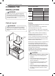
Product Specifications Dimensions Tolerances: +1/16", -0 (1.6 mm, -0), unless otherwise stated. NOTE The exhaust duct(s) and electrical wiring can be connected from either the top or the back of the hood. 10 5/8″ 10 3/8″ 1 3/16″ 5 5/16″ 18 7/16″ STANDARD min. ducted - 27″ min. recirc. - 31″ max.
PRODUCT OVERVIEW ENGLISH PRODUCT OVERVIEW Parts 3 2 1 4 5 1 Hood 4 Mesh Filter 2 Icon Touch Control Panel 5 Side Panel (Only for LSHD3689BD, LSHD3680ST) 3 LED Strip Light 9 Accessories Included Accessories Manual Duct cover bracket Duct cover Manual M6 x 1-1/2" (2) M4 x 8 (2) Wire Caps (3) M6 x 1" (3)
Planning the Installation Planning the Installation Minimum Cabinet Width Standard Duct Cover Warning Observe all governing codes and ordinances during planning and installation. Contact your local building department for further information. Use only duct work deemed acceptable by state, municipal and local codes.
Planning the Installation 11 ENGLISH Ducting Options Warning Fire Hazard •• NEVER exhaust air or terminate duct work into spaces between walls, crawl spaces, ceiling, attics or garages. •• All exhaust must be ducted to the outside. •• Use metal ductwork only. •• Fasten all connections with sheet metal screws and tape all joints with certified Silver Tape or Duct Tape.
Planning the Installation Ducting Calculation Sheet Duct pieces Equivalent length x number used = Total Duct pieces Equivalent length x number used = Total 3-1/4" x 10" Rect., straight 1 Ft. x( )= Ft. 6" Round 30 Ft. wall cap with damper x( )= Ft. 6" Round, straight 1 Ft. x( )= Ft. 6" Round, roof cap 30 Ft. x( )= Ft. 7"-10" Round, straight 1 Ft. x( )= Ft. 1 Ft. x( )= Ft. 3-1/4" x 10" Rect.90˚ elbow 15 Ft. 6" round to 3-1/4" x 10" rect. transition 16 Ft.
Planning the Installation 13 Electrical Supply Wherever possible, reduce the number of transitions and turns to as few sharp angles as possible. Two staggered 45° angles are better than one 90°. This appliance requires a 120V 60Hz electrical supply, and must be connected to an individual, properly grounded branch circuit, protected by a 15 or 20 ampere circuit breaker or time delay fuse. Wiring must be 2 wire w/ ground. Please also refer to the Electrical Diagram label on product.
Installation Instructions Installation Instructions WARNING •• Do not install the range hood unless the electrical service provided meets the range hood specifications. •• Observe all governing codes and ordinances during installation. Contact your local building department for further information. •• A qualified technician must complete the installation of this built-in appliance. More than one person is required to raise the hood into place.
Wiring Diagram 15 Models Volts HZ MAX Amps LSHD3089BD LSHD3080ST LSHD3689BD LSHD3680ST 120 60 4 ENGLISH Wiring Diagram
Memo Memo
ESPAÑOL GUÍA DE INSTALACIÓN CAMPANA Lea atentamente estas instrucciones antes de instalar y poner la campana en funcionamiento. LSHD3689BD LSHD3680ST LSHD3089BD LSHD3080ST www.lg.com MFL70208702_00 Copyright © 2017 LG Electronics Inc. Todos los Derechos Reservados.
2 ÍNDICE ÍNDICE 3 Antes de comenzar 14 INSTRUCCIONES DE INSTALACIÓN 14 Montaje de la campana extractora 4 INSTRUCCIONES IMPORTANTES DE SEGURIDAD 7 ESPECIFICACIONES DEL PRODUCTO 7 Especificaciones generales 8 Dimensiones 9 DESCRIPCIÓN GENERAL DEL PRODUCTO 9 Piezas 9 Lista de piezas 10 PLANIFICACIÓN DE LA INSTALACIÓN 10 11 12 13 13 Disposición de alacenas Opciones de conducto Hoja de cálculo de conducto Suministro de energía Verifique el contenido del embalaje 15 DIAGRAMA DE CABLEADO
Antes de comenzar 3 Antes de comenzar IMPORTANTE: Placa de datos del artefacto •• La placa de datos de este artefacto contiene información del número de serie y el modelo, y los requisitos eléctricos. •• Se encuentra ubicada dentro de la campana, detrás de los filtros, en la parte posterior del chasis. Retire los filtros para verla. Todas las especificaciones están sujetas a cambios sin previo aviso. LG STUDIO no se hace responsable por cambios en las especificaciones.
4 INSTRUCCIONES IMPORTANTES DE SEGURIDAD INSTRUCCIONES IMPORTANTES DE SEGURIDAD Lea y siga todas las instrucciones cuando utilice la cocina para evitar riesgos de incendios, descargas eléctricas, lesiones personales o daños. Esta guía no incluye todas las situaciones posibles que podrían ocurrir. Siempre comuníquese con su agente de servicio técnico o con el fabricante cuando haya problemas que no comprenda. Descargue este manual en: http://www.lg.com Este es el símbolo de alerta de seguridad.
INSTRUCCIONES IMPORTANTES DE SEGURIDAD 5 ADVERTENCIA PRECAUCIÓN Solo para uso de ventilación general. No lo utilice para la extracción de materiales y vapores peligrosos o explosivos.
6 INSTRUCCIONES IMPORTANTES DE SEGURIDAD ADVERTENCIA •• Lea el manual del propietario por completo antes de usar el aparato. Limpie el aparato solamente como se indica en el manual del propietario. Use únicamente los productos de limpieza especificados. •• No manipule indebidamente los controles. •• Nunca permita que el/los filtro(s) se bloquee(n) u obstruya(n). No permita que objetos extraños, tales como cigarrillos o servilletas, sean aspirados por la campana.
ESPECIFICACIONES DEL PRODUCTO 7 ESPECIFICACIONES DEL PRODUCTO Especificaciones generales Todos los modelos 5 Filtros Filtros de malla de aluminio Carga total de conexión 120 V CA, 60 Hz, 4 A.
8 ESPECIFICACIONES DEL PRODUCTO Dimensiones Tolerancias: +1/16", -0 (1.6 mm, -0), a menos que se especifique lo contrario. NOTA El/los conducto(s) de escape y el cableado eléctrico se pueden conectar desde la parte superior o posterior de la campana.
DESCRIPCIÓN GENERAL DEL PRODUCTO 9 DESCRIPCIÓN GENERAL DEL PRODUCTO Piezas 2 1 4 ESPAÑOL 3 5 1 Campana iltros de malla 4 F 2 Panel de control táctil con iconos 5 Panel lateral (solo para LSHD3689BD, LSHD3680ST) 3 Luz led Lista de piezas Accesorios incluidos Manual Soporte de cubierta de conducto Cubierta de conducto Manual M6 x 1-1/2" (2) M4 x 8 (2) Remates para cables (3) M6 x 1" (3)
10 PLANIFICACIÓN DE LA INSTALACIÓN PLANIFICACIÓN DE LA INSTALACIÓN ADVERTENCIA Respete todos los códigos y las ordenanzas vigentes durante la planificación y la instalación. Póngase en contacto con el departamento de construcción de su localidad para obtener más información. Utilice solamente conductos considerados aceptables por las normas estatales, municipales y locales.
PLANIFICACIÓN DE LA INSTALACIÓN 11 Opciones de conducto ADVERTENCIA Riesgo de fuego ESPAÑOL •• NUNCA extraiga aire o termine el conducto en espacios entre paredes, espacios angostos, techos, áticos o garajes. •• Toda la extracción debe realizarse al exterior. •• Utilice únicamente conductos de metal. •• Fije todas las conexiones con tornillos para metal y cubra todas las juntas con cinta plateada o cinta de conducto certificada.
12 PLANIFICACIÓN DE LA INSTALACIÓN Hoja de cálculo de conducto Piezas de conducto Longitud equivalente x número usado Piezas de conducto Total = Rectangular, recto 3-1/4" x 10" 1 Ft. x( )= Ft. 6" redondo, recto 1 Ft. x( )= Ft. 7"-10" 1 Ft. redondo, recto x( )= Ft. Longitud equivalente x número usado Total = 30 Ft. 6" tope de pared redondo con compuerta x( )= Ft. 6" redondo, 30 Ft. tope de tejado x( )= Ft. 1 Ft.
PLANIFICACIÓN DE LA INSTALACIÓN 13 Suministro eléctrico Siempre que sea posible, reduzca el número de transiciones y curvas al menor número de ángulos agudos que sea posible. Dos instancias de ángulos de 45° son mejores que una de 90°. Este aparato requiere un suministro eléctrico de 120V 60Hz, y debe conectarse a un circuito ramal con una conexión a tierra adecuada, protegido por un interruptor de circuitos de 15 o 20 amperios o un fusible de acción retardada.
14 INSTRUCCIONES DE INSTALACIÓN INSTRUCCIONES DE INSTALACIÓN ADVERTENCIA •• No instale la campana extractora, a menos que el suministro de energía eléctrica del domicilio cumpla con las especificaciones de la campana. •• Respete todos los códigos y las ordenanzas vigentes durante la instalación. Póngase en contacto con el departamento de construcción de su localidad para obtener más información. •• La instalación de este artefacto empotrable debe ser realizada por un técnico calificado.
DIAGRAMA DE CABLEADO 15 DIAGRAMA DE CABLEADO Voltios Hz Amps Máx.
LG Customer Information Center 1-800-243-0000 USA Register your product Online! www.lg.