OWNER’S MANUAL LED TV* * LG LED TVs are LCD TVs with LED backlighting. Click! User Guide Please read this manual carefully before operating your set and retain it for future reference. UB85** UB93** UB95** UB98** UC97** UC9* *MFL68066606* UG88** www.lg.
TABLE OF CONTENTS ENGLISH ENG TABLE OF CONTENTS 3 3 3 LICENSES 42 42 - Digital optical audio Connection OPEN SOURCE SOFTWARE NOTICE 42 Headphone Connection 43 USB Connection 43 CI module Connection 44 Euro Scart Connection 45 REMOTE CONTROL 47 MAGIC REMOTE FUNCTIONS 48 Registering Magic Remote 48 How to use Magic Remote EXTERNAL CONTROL DEVICE SETUP 4 SAFETY INSTRUCTIONS 11 Viewing 3D Imaging (Only 3D models) 13 INSTALLATION PROCEDURE 13 ASSEMBLING AND PREPARING 13 Unpac
LICENSES / OPEN SOURCE SOFTWARE NOTICE / EXTERNAL CONTROL DEVICE SETUP 3 Supported licenses may differ by model. For more information about licenses, visit www.lg.com. OPEN SOURCE SOFTWARE NOTICE To obtain the source code under GPL, LGPL, MPL and other open source licenses, that is contained in this product, please visit http://opensource.lge.com. In addition to the source code, all referred license terms, warranty disclaimers and copyright notices are available for download.
SAFETY INSTRUCTIONS ENGLISH ENG SAFETY INSTRUCTIONS Please read these safety precautions carefully before using the product.
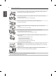
SAFETY INSTRUCTIONS yy When mounting TV onto wall make sure to neatly install and isolate cabling from rear of TV as to not create possibility of electric shock/fire hazard. yy Do not plug too many electrical devices into a single multiple electrical outlet. Otherwise, this may result in fire due to over-heating. yy Do not drop the product or let it fall over when connecting external devices. Otherwise, this may result in injury or damage to the product.
SAFETY INSTRUCTIONS ENGLISH ENG yy Do not spray water on the product or scrub with an inflammable substance (thinner or benzene). Fire or electric shock accident can occur. yy Do not allow any impact, shock or any objects to fall into the unit, and do not drop anything onto the screen. You may be injured or the product can be damaged. yy Never touch this product or antenna during a thunder or lighting storm. You may be electrocuted.
SAFETY INSTRUCTIONS yy Install the product where no radio wave occurs. yy There should be enough distance between an outside antenna and power lines to keep the former from touching the latter even when the antenna falls. This may cause an electric shock. yy Do not install the product on places such as unstable shelves or inclined surfaces. Also avoid places where there is vibration or where the product cannot be fully supported.
SAFETY INSTRUCTIONS ENGLISH ENG yy Make sure there are no objects between the remote control and its sensor. yy Signal from Remote Control can be interrupted due to external/internal lighting eg Sunlight, fluorescent lighting. If this occurs turn off lighting or darken viewing area. yy When connecting external devices such as video game consoles, make sure the connecting cables are long enough. Otherwise, the product may fall over, which may cause injury or damage the product.
SAFETY INSTRUCTIONS yy When cleaning the product and its components, unplug the power first and wipe it with a soft cloth. Applying excessive force may cause scratches or discolouration. Do not spray with water or wipe with a wet cloth. Never use glass cleaner, car or industrial shiner, abrasives or wax, benzene, alcohol etc., which can damage the product and its panel. Otherwise, this may result in fire, electric shock or product damage (deformation, corrosion or breakage).
SAFETY INSTRUCTIONS ENGLISH ENG yy You may find different brightness and colour of the panel depending on your viewing position(left/right/top/down). This phenomenon occurs due to the characteristic of the panel. It is not related with the product performance, and it is not malfunction. yy Displaying a still image (e.g.
SAFETY INSTRUCTIONS 11 Viewing 3D Imaging (Only 3D models) Viewing Environment yy Viewing Time -- When watching 3D contents, take 5 - 15 minute breaks every hour. Viewing 3D contents for a long period of time may cause headache, dizziness, fatigue or eye strain. Those that have a photosensitive seizure or chronic illness yy Some users may experience a seizure or other abnormal symptoms when they are exposed to a flashing light or particular pattern from 3D contents.
SAFETY INSTRUCTIONS ENGLISH ENG CAUTION Viewing Environment yy Viewing Distance - Maintain a distance of at least twice the screen diagonal length when watching 3D contents. If you feel discomfort in viewing 3D contents, move further away from the TV. Viewing Age yy Infants/Children -- Usage/ Viewing 3D contents for children under the age of 6 are prohibited.
INSTALLATION PROCEDURE / ASSEMBLING AND PREPARING 13 INSTALLATION PROCEDURE 1 2 3 4 Open the package and make sure all the accessories are included. Attach the stand to the TV set. Connect an external device to the TV set. Make sure the network connection is available. You can use the TV network functions only when the network connection is made. * If the TV is turned on for the first time after it was shipped from the factory, initialization of the TV may take a few minutes.
ASSEMBLING AND PREPARING ENGLISH ENG NOTE How to use the ferrite core (Depending on model) yy Use the ferrite core to reduce the electromagnetic interference in the LAN cable. Wind the LAN cable once on the ferrite core. Place the ferrite core close to the TV.
ASSEMBLING AND PREPARING 15 ENGLISH ENG ENERGY AV MODE INPUT TV SAVING 1 2 3 4 5 6 7 8 9 0 FLASHBK LIST MARK FAV VOL 3D CH P A G E MUTE MENU INFO Q.MENU Tag On ENTER BACK EXIT L/R SELECT FREEZE RATIO Remote Control, Batteries (AAA) (Depending on model) The remote control will not be included for all sales market. (See p. 45, 46) Magic remote, batteries (AA) (Only UB85**, UB93**, UB95**, UB98**, UC97**, UC9*, UG88**) (See p.
1 2 16 ASSEMBLING AND PREPARING ENGLISH ENG Stand Body / Stand Base (Only UC97**) (See p. 27, 28) Stand Body / Stand Base (Only UG88**) (See p. 28) Stand Screws 8EA, M4 x L20 (Only UB85**-ZA, UB93**, UB95**-ZA) 4EA, M4 x L20 (Only UB85**-ZD, UB95**-ZB, UC97**) (See p. 23, 24, 28) Stand Screws 4EA, M4 x L10 (Only UB85**-ZD, UB95**-ZB, UC97**) 2EA, M4 X L10 (Only UG88**) (See p.24, 27, 28) Stand Screws 4EA, M6 x L47 (Only 65UB98**) (See p.25) Stand Screws 4EA, M6 x L52 (Only 79/84UB98**) (See p.
ASSEMBLING AND PREPARING 17 ENGLISH ENG AV Port Cover (Only UC9*) (See p. 34) Separate purchase Optional extras can be changed or modified for quality improvement without any notification. Contact your dealer for buying these items. These devices only work with certain models.
ASSEMBLING AND PREPARING ENGLISH ENG Parts and buttons A type : UB85**-ZA B type : UB85**-ZD Screen Screen Speakers Speakers Remote control and Intelligent1 sensors Power Indicator Joystick Button2 Remote control and Intelligent1 sensors Power Indicator D type : UB95**-ZB C type : UB93**, UB95**-ZA Screen Screen Speakers Speakers Remote control and Intelligent1 sensors LG Logo light Joystick Button2 Joystick Button3 Remote control and Intelligent1 sensors LG Logo light Joystick Butt
ASSEMBLING AND PREPARING F type : 84UB98** E type : 65/79UB98** Screen Screen Speakers Speakers Speakers(Only 79UB98**) Speakers Joystick Button 2 G type : 98UB98** Built-in camera Screen Remote control and Intelligent1 sensors LG Logo light Joystick Button3 H type : UC97** Screen Speakers Remote control and Intelligent1 sensors LG Logo light Sliding Speaker Joystick Button3 Remote control and Intelligent1 sensors LG Logo light Joystick Button2 ENGLISH ENG Built-in camera Built-in camer
ASSEMBLING AND PREPARING I Type : UC9* ENGLISH ENG Built-in Camera J Type : UG88** Screen Screen Speakers Speakers Remote control and Intelligent1 sensors Power Indicator Joystick Button3 Remote control and Intelligent1 sensors LG Logo light Joystick Button2 CAUTION yy Do NOT place any objects or body parts in area between TV Screen and Speaker Stand assembly. It could cause personal Injury or damage to product .
ASSEMBLING AND PREPARING 21 Using the joystick button Basic Functions Power On When the TV is turned off, place your finger on the joystick button and press it once and release it. Power Off When the TV is turned on, place your finger on the joystick button and press it once for a few seconds and release it. Volume Control If you place your finger over the joystick button and move it left or right, you can adjust the volume level you want.
ASSEMBLING AND PREPARING ENGLISH ENG Lifting and moving the TV Please note the following advice to prevent the TV from being scratched or damaged and for safe transportation regardless of its type and size. yy When transporting a large TV, there should be at least 2 people. yy When transporting the TV by hand, hold the TV as shown in the following illustration. CAUTION yy Avoid touching the screen at all times, as this may result in damage to the screen.
ASSEMBLING AND PREPARING Setting up the TV 23 ENGLISH ENG 2 Image shown may differ from your TV. Attaching the stand UB85**-ZA, UB93**, UB95**-ZA 1 Stand Body (L) 1 Stand Body (R) 2 Stand Base 1 Attach the stand to the TV using the upper mounting hole on the back of the TV. 2 Attach the stand to the TV using the lower connection on the back of the TV. M4 x L20 4EA 3 NOTE yy Be sure to check the Stand Body (L), (R), when installing on the stand base.
ASSEMBLING AND PREPARING UB85**-ZD, UB95**-ZB ENGLISH ENG 3 1 Stand Body (R) Stand Body (L) Stand Base 1 Attach the stand to the TV using the upper mounting hole on the back of the TV. 2 Attach the stand to the TV using the lower connection on the back of the TV. 2 4 4EA M4 x L10 NOTE yy Be sure to check the Stand Body (L), (R), when installing on the stand base.
ASSEMBLING AND PREPARING 65/79/84UB98** 1 ENGLISH ENG 3 (Only 65/79UB98**) 1 2 Wrench Stand Base 4EA 2 M6 x L47 (Only 65UB98**) 1 M6 x L52 (Only 79UB98**) 2 (Only 84UB98**) 1 2 Wrench 4EA M6 x L52 1 25 4EA (Insulation Holder) 2
ASSEMBLING AND PREPARING ENGLISH ENG CAUTION y Make sure that the screws are inserted correctly and fastened securely. (If they are not fastened securely enough, the TV may tilt forward after being installed.) 98UB98** 1 Wrench 1 2 1 2 Mold M6 x L47 6EA NOTE y The stand screws are already attached at the back of the TV. Please use these attached screw to assemble the TV and stand.
ASSEMBLING AND PREPARING UC97** 1 ENGLISH ENG 2 27 2 1 Stand Body (L) Stand Body (R) Stand Base Stand Base 1 2 M4 x L10 4EA 3 Wrench 2 2 3 1 When assembling the stand, lay the front screen protective package included in the product box on a table or flat surface and then place the TV screen face down on the protective package. 2 Attach the stand to the TV using the upper mounting hole on the back of the TV. 3 Attach the stand to the TV using the lower connection on the back of the TV.
28 ASSEMBLING AND PREPARING ENGLISH ENG 3 2 2 3 1 1 M4 x L20 4EA * Use at least two people to attach the stand to the TV. 1 1 When assembling the stand, lay the front screen protective package included in the product box on a table or flat surface and then place the TV screen face down on the protective package. 2 Attach the stand to the TV using the upper mounting hole on the back of the TV. 3 Attach the stand to the TV using the lower connection on the back of the TV.
ASSEMBLING AND PREPARING yy When attaching the stand to the TV set, place the screen facing down on a cushioned table or flat surface to protect the screen from scratches. (Only UB85**, UB93**, UB95**, UB98**) yy Make sure that the screws are inserted correctly and fastened securely. (If they are not fastened securely enough, the TV may tilt forward after being installed.) Do not use too much force and over tighten the screws; otherwise screw may be damaged and not tighten correctly.
ASSEMBLING AND PREPARING Mounting on a wall Securing the TV to a wall ENGLISH ENG (This feature is not available for all models.) (Only 105UC9*) (Only 98UB98**) Attach an optional wall mount bracket at the rear of the TV carefully and install the wall mount bracket on a solid wall perpendicular to the floor. When you attach the TV to other building materials, please contact qualified personnel. LG recommends that wall mounting be performed by a qualified professional installer.
ASSEMBLING AND PREPARING MSW240 LSW640B A B CAUTION yy Disconnect the power first, and then move or install the TV. Otherwise electric shock may occur. yy If you install the TV on a ceiling or slanted wall, it may fall and result in severe injury. Use an authorized LG wall mount and contact the local dealer or qualified personnel. yy Do not over tighten the screws as this may cause damage to the TV and void your warranty. yy Use the screws and wall mounts that meet the VESA standard.
ASSEMBLING AND PREPARING ENGLISH ENG Tidying cables (Only UC97**) Image shown may differ from your TV. 1 Gather and bind the cables with the Cable Holder and the Cable Management. 2 Fix the Cable Management firmly to the TV.
ASSEMBLING AND PREPARING 1 Fix the Cable Management firmly to the TV. (Only 65/79/84UB98**) (Only UC9*) Cable Holder ENGLISH ENG 1 Gather and bind the cables with the Cable Holder. 33 Cable Management CAUTION (Only UG88**) Cable Holder yy Do not move the TV by holding the cable holders, as the cable holders may break, and injuries and damage to the TV may occur.
ASSEMBLING AND PREPARING ENGLISH ENG Assembling the AV cover (Only 98UB98**) 1 Insert the cover holder attached to the AV port cover into the hole of the main body of the product as illustrated. 2 Attach the port cover onto the AV port part. (The cover remains attached through the use of a magnet.) 1 (Only UC9*) 1 Insert the cover holder attached to the AV port cover into the hole of the main body of the product as illustrated.
Sliding Speaker 35 CAUTION y When the Sliding Speaker is operating (when the TV is turned on/off), ensure that children do not put their hands near the operating part of the speaker (at the bottom of the TV) and that they do not crawl into the space below the TV. - Their hands may get caught and injured due to the operation of the speaker. (Only 98UB98**) Sliding Speaker 1 When TV is turned ON - the hidden speaker slides out from inside the TV.
ASSEMBLING AND PREPARING ENGLISH ENG Using Built-in Camera Preparing Built-in Camera (Only UB98**, UC9*) (This feature is not available for all models.) You can make a Skype video call or use the motion recognition function using the built-in camera of the TV. This TV does not support the use of an external camera. 1 Pull up the slide at the back of the TV.
MAKING CONNECTIONS MAKING CONNECTIONS This section on MAKING CONNECTIONS mainly uses diagrams for the UB85** models. Connect various external devices to the TV and switch input modes to select an external device. For more information on external device’s connection, refer to the manual provided with each device. Available external devices are: HD receivers, DVD players, VCRs, audio systems, USB storage devices, PC, gaming devices, and other external devices.
MAKING CONNECTIONS ENGLISH ENG Satellite dish Connection Antenna Connection (Only satellite models) IN IN (*Not Provided) 13 / 18 V 700mA Max LNB IN Satellite ANTENNA / CABLE (*Not Provided) Wall Antenna Socket Connect the TV to a wall antenna socket with an RF cable (75 Ω). NOTE yy Use a signal splitter to use more than 2 TVs. yy If the image quality is poor, install a signal amplifier properly to improve the image quality.
MAKING CONNECTIONS 4 (MHL) (4K@60Hz) / DVI IN 3 (10Bit) 2 (ARC) 1 (HDCP 2.2) DVD / Blu-Ray / HD Cable Box / HD STB / PC 1) HDMI specifications may be different for each input port, so make sure to check the device specifications before connecting. 2) The HDMI IN 3 port is especially suitable for the specifications to enjoy UHD Video (4:4:4, 4:2:2) of 4K @ 50/60 Hz. However, video or audio may not be supported depending on the specifications of the external equipment.
MAKING CONNECTIONS AV2 IN AV2 VIDEO COMPONENT AUDIO PR Y AV2 YELLOW (Use the composite gender cable provided.) GREEN (Use the component gender cable provided.) BLUE RED BLUE GREEN GREEN BLUE RED GREEN NOTE RED WHITE DVD / Blu-Ray / HD Cable Box / PC / HD STB yy Depending on the graphics card, DOS mode may not work if a HDMI to DVI Cable is in use. yy When using the DVI/HDMI cable, single link is supported.
MHL Connection COMPONENT AUDIO PR PB Y 11(HDCP 2.2) 2(ARC) 2 VIDEO IN 3(10Bit) AV2 (4K@60Hz) / DVI/ DVI IN IN 4 (MHL) Composite Connection 41 ENGLISH ENG ponent provided.) MAKING CONNECTIONS AV2 YELLOW (Use the composite gender cable provided.
MAKING CONNECTIONS ENGLISH ENG Audio Connection Headphone Connection OUT OPTICAL DIGITAL AUDIO OUT Ext.SPEAKER / H/P (*Not Provided) (*Not Provided) Transmits the headphone signal from the TV to an external device. Connect the external device and the TV with the headphone as shown. NOTE Digital Audio System OPTICAL AUDIO IN You may use an external audio system instead of the built-in speaker.
MAKING CONNECTIONS HDD IN 1(USB 3.0 IN) 2 USB IN 3 ▼ PCMCIA CARD SLOT ▼ CI module Connection ENGLISH ENG USB Connection 43 (*Not Provided) HUB (*Not Provided) USB (*Not Provided) Connect a USB storage device such as a USB flash memory, external hard drive or a USB memory card reader to the TV and access the SmartShare menu to use various multimedia files. ▼ PCMCIA CARD SLOT ▼ HDD (*Not Provided) NOTE yy Some USB Hubs may not work.
MAKING CONNECTIONS ENGLISH ENG Euro Scart Connection IN / OUT (RGB) AV1 (Use the Scart gender cable provided - Depending on model) (*Not Provided) Transmits the video and audio signals from an external device to the TV set. Connect the external device and the TV set with the euro scart cable (or Scart gender cable) as shown. Output Type Current input mode Digital TV AV1 (TV Out1) Digital TV Analogue TV, AV Component Analogue TV HDMI 1 TV Out : Outputs Analogue TV or Digital TV signals.
REMOTE CONTROL 45 The descriptions in this manual are based on the buttons on the remote control. Please read this manual carefully and use the TV correctly. To replace batteries, open the battery cover, replace batteries (1.5 V AAA) matching the and ends to the label inside the compartment, and close the battery cover. To remove the batteries, perform the installation actions in reverse. or CAUTION yy Do not mix old and new batteries, as this may damage the remote control.
REMOTE CONTROL (Depending on model) ENGLISH ENG TV / RAD Q.MENU 2 5 8 3 6 9 0 Q.VIEW [ 1 4 7 FAV MUTE 1 RECENT MENU TEXT T.OPT EXIT T M AD 2 REC/ AD/PIP (POWER) Turns the TV on or off. TV/RAD Selects Radio, TV and DTV programme. INPUT Changes the input source. SETTINGS Accesses the main menus. Q. MENU Accesses the quick menus. INFO Views the information of the current programme and screen. SUBTITLE Recalls your preferred subtitle in digital mode. GUIDE Shows programme guide.
MAGIC REMOTE FUNCTIONS 47 When the message “Magic Remote battery is low. Change the battery.” is displayed, replace the battery. To replace batteries, open the battery cover, replace batteries (1.5 V AA) matching and ends to the label inside the compartment, and close the battery cover. Be sure to point the remote control toward the remote control sensor on the TV. To remove the batteries, perform the installation actions in reverse.
MAGIC REMOTE FUNCTIONS ENGLISH ENG Voice recognition Network connection is required to use the voice recognition function. 1. Press the Voice recognition button. 2. Speak when the voice display window appears on the left of the TV screen. • The voice recognition may fail when you speak too fast or too slow. • Use the Magic remote control no further than 10 cm from your face.
MAGIC REMOTE FUNCTIONS yy Use the Magic Remote within the maximum communication distance (10 m). Using the Magic Remote beyond this distance, or with an object obstructing it, may cause a communication failure. yy A communication failure may occur due to nearby devices. Electrical devices such as a microwave oven or wireless LAN product may cause interference, as these use the same bandwidth (2.4 GHz) as the Magic Remote.
USING THE USER GUIDE / MAINTENANCE ENGLISH ENG USING THE USER GUIDE User Guide allows you to more easily access the detailed TV information. 1 Press the (Home) button to access the Home menu. 2 Select User Guide and press Wheel(OK). BACK HOME P MY APPS NOTE yy You can also access the User Guide by pressing (User Guide) in the remote control. (Depending on model) MAINTENANCE Cleaning your TV Clean your TV regularly to keep the best performance and to extend the product lifespan.
SPECIFICATIONS 51 Problem Solution Cannot control the TV with the remote control. yy Check the remote control sensor on the product and try again. yy Check if there is any obstacle between the product and the remote control. yy Check if the batteries are still working and properly installed ( to , to ). No image display and no sound is produced. yy Check if the product is turned on. yy Check if the power cord is connected to a wall outlet.
SPECIFICATIONS (Only UB98**, UC9*) ENGLISH ENG Wireless LAN module (LGSWF41) specification Standard IEEE 802.11a/b/g/n/ac 2400 to 2483.5 MHz 5150 to 5250 MHz 5725 to 5850 MHz (for Non EU) Frequency Range 802.11a: 14.5 dBm 802.11b: 16 dBm 802.11g: 13.5 dBm 802.11n - 2.4GHz: 14 dBm 802.11n - 5GHz: 15.5 dBm 802.11ac - 5GHz : 16 dBm Output Power (Max.
SPECIFICATIONS 53 Product specifications may be changed without prior notice due to upgrade of product functions. 49UB850V-ZD 49UB850V-ZA 49UB856V-ZD With stand (mm) 1093 x 689 x 242 1093 x 681 x 237 Without stand (mm) 1093 x 646 x 38.2 1093 x 646 x 38.2 With stand (kg) 18.2 18.5 Without stand (kg) 17.5 17.
SPECIFICATIONS ENGLISH ENG MODELS Dimensions (W x H x D) 55UB95** 55UB950V-ZA 55UB950V-ZB With stand (mm) 1232 x 782 x 260 1232 x 780 x 242 Without stand (mm) 1232 x 734 x 37 1232 x 734 x 37 With stand (kg) 23.8 24.2 Without stand (kg) 23.1 23.
SPECIFICATIONS With stand (mm) Dimensions (W x H x D) Without stand (mm) 65UC97** 55UC970V-ZA 65UC970V-ZA 1238.7 x 757.5 x 289.0 1456.9 x 888.0 x 316.4 1238.7 x 730 x 72.1 1456.9 x 853.2 x 71.5 With stand (kg) 27.7 34.6 Without stand (kg) 26.2 32.
Please contact LG First. If you have any inquiries or comments, please contact LG customer information centre. Customer Information Centre Country Record the model number and serial number of the TV. Refer to the label on the back cover and quote this information to your dealer when requiring any service.
OWNER’S MANUAL EXTERNAL CONTROL DEVICE SETUP Please read this manual carefully before operating the set and retain it for future reference. www.lg.
2 KEY CODES ENGLISH ENG KEY CODES • This feature is not available for all models.
EXTERNAL CONTROL DEVICE SETUP 3 • Image shown may differ from your TV. Connect the USB to Serial converter/RS-232C input jack to an external control device (such as a computer or an A/V control system) to control the product’s functions externally. Note: The type of control port on the TV can be different between model series. * Please be advised that not all models support this type of connectivity. * Cable is not provided.
USB USB IN IN 4 EXTERNAL CONTROL DEVICE SETUP (PC) (PC) (TV) (TV) RS-232C IN (CONTROL SERVICE) • You need to purchase the phone-jack to RS-232 cable required for &the connection between the PC and the TV, which is specified in the manual. RS-232C IN (PC) (PC) (CONTROL & SERVICE) * For other models, connect to the USB port. * The connection interface may differ from your TV.
EXTERNAL CONTROL DEVICE SETUP 5 • Baud rate : 9600 bps (UART) • Data length : 8 bits • Parity : None ENGLISH ENG Communication Parameters • Stop bit : 1 bit • Communication code : ASCII code • Use a crossed (reverse) cable. Command reference list (Depending on model) COMMAND1 COMMAND2 DATA (Hexadecimal) 01. Power* k a 00 to 01 02. Aspect Ratio k c (p.7) 03. Screen Mute k d (p.7) k e 00 to 01 k f 00 to 64 06. Contrast k g 00 to 64 07. Brightness k h 00 to 64 08.
6 EXTERNAL CONTROL DEVICE SETUP ENGLISH ENG Transmission / Receiving Protocol Transmission [Command1][Command2][ ][Set ID][ ][Data][Cr] [Command 1] : First command to control the TV. (j, k, m or x) [Command 2] : Second command to control the TV. [Set ID] : You can adjust the [Set ID] to choose desired monitor ID number in option menu. Adjustment range in TV is 1 to 99. If [Set ID] value is selected to ‘0’, every connected set can be controlled.
EXTERNAL CONTROL DEVICE SETUP 7 01. Power (Command: k a) ►► To control Power *On or Off of the set. Transmission[k][a][ ][Set ID][ ][Data][Cr] Data 00 : Power Off 01 : *Power On Ack [a][ ][Set ID][ ][OK/NG][Data][x] ►► To Show TV is Power On or *Off Transmission [k][a][ ][Set ID][ ][FF][Cr] Ack [a][ ][Set ID][ ][OK][Data][x] * Similarly, if other functions transmit ‘FF’ data based on this format, Acknowledgement feedback presents status about each function. 02.
8 EXTERNAL CONTROL DEVICE SETUP ENGLISH ENG Data Min : 00 to Max : 64 * (Depending on model) Ack [i][ ][Set ID][ ][OK/NG][Data][x] 09. Tint (Command: k j) ►► To adjust the screen tint. You can also adjust tint in the PICTURE menu. Transmission [k][j][ ][Set ID][ ][Data][Cr] Data Red : 00 to Green : 64 Ack [j][ ][Set ID][ ][OK/NG][Data][x] 10. Sharpness (Command: k k) ►► To adjust the screen sharpness. You can also adjust sharpness in the PICTURE menu.
EXTERNAL CONTROL DEVICE SETUP 0 0 5th Band 0 0 1 0 1 20(decimal) Acknowledgement [v][ ][Set ID][ ][OK/NG][Data][x] * It depends on model, and can adjust when sound mode is EQ adjustable value. 19. Energy Saving (Command: j q) ►► To reduce the power consumption of the TV. You can also adjust Energy Saving in PICTURE menu.
10 EXTERNAL CONTROL DEVICE SETUP ENGLISH ENG Number - 22 : Antenna TV (DTV) – Don’t Use Physical Channel Number - 26 : Cable TV (CADTV) - Don’t Use Physical Channel Number - 46 : Cable TV (CADTV) – Use Major Channel Number Only (One Part Channel) Two bytes are available for each major and minor channel data, but usually the low byte is used alone (high byte is 0). * Tune Command Examples: 1. Tune to the Analog cable (NTSC) channel 35.
EXTERNAL CONTROL DEVICE SETUP ►► To select input source for main picture. Transmission [x][b][ ][Set ID][ ][Data][Cr] Data 00 : DTV 01 : CADTV 02 : Satellite DTV 10 : ATV ISDB-BS (Japan) 03 : ISDB-CS1 (Japan) 04 : ISDB-CS2 (Japan) 11 : CATV O 01 X X X 02 X X X 03 X O O [Data03][x] [t][ ][Set ID][ ][NG][Data00][x] 40 : Component1 60 : RGB 41 : Component2 90 : HDMI1 92 : HDMI3 91 : HDMI2 93 : HDMI4 26.
12 EXTERNAL CONTROL DEVICE SETUP ENGLISH ENG 27. Auto Configure (Command: j u) (Depending on model) ►► To adjust picture position and minimize image shaking automatically. It works only in RGB (PC) mode.