English OWNER'S MANUAL CLOUD MONITOR Please read the safety information carefully before using the product. CLOUD Monitor Model 23CAV42K www.lg.
Table of Contents TABLE OF CONTENTS English ENG 3 ASSEMBLING AND PREPARING 22 TROUBLESHOOTING 3 Unpacking 4 Parts and buttons 24 PRODUCT SPECIFICATION 5 Lifting and moving the Monitor 25 Preset Mode 5 Setting Up the Monitor set 25 Power Indicator 5 - Attaching the Stand Base 6 - Detaching the stand base 6 - Detaching the stand body 26 PROPER POSTURE 7 - Mounting on a table 26 Proper posture for using the monitor 7 - Adjusting the stand height 8 - Adjusting the angle 27
ASSEMBLING AND PREPARING 3 ASSEMBLING AND PREPARING ENG English Unpacking Please check whether all the components are included in the box before using the product. If there are missing components, contact the retail store where you purchased the product. Note that the product and components may look different from those shown here. User Manual/Card Stand Base Power Cord Adaptor 15-pin D-SUB Signal Cable CAUTION Only use an approved LG power adapter.
ASSEMBLING AND PREPARING Parts and buttons English ENG Input Connectors (See p.14 ) Power Indicator yyLED On : Power is on yyLED Off: Power is off (Power Button) MENU 92/ CLOUD AUTO INPUT EXIT Front Side Buttons 1 1 Input Connectors (See p.
ASSEMBLING AND PREPARING Please heed the following information when moving the monitor. CAUTION yyAvoid touching the screen at all times, as this may result in damage to the screen or pixels . Setting Up the Monitor set Attaching the Stand Base 1 Place the monitor's screen face down. CAUTION To protect the screen from scratches, yy cover the surface with a soft cloth.
ASSEMBLING AND PREPARING English ENG Detaching the stand base Detaching the stand body 1 Place the monitor's screen face down. 1 Place the monitor's screen face down. To To protect the screen from scratches, cover the surface with a soft cloth. protect the screen from scratches, cover the surface with a soft cloth. 2 Using a screwdriver, remove the four screws and detach the stand from the monitor. 2 Using a coin, turn the screw in the stand base counterclockwise.
ASSEMBLING AND PREPARING Adjusting the stand height 1 Lift the monitor and place it on the table in an 1 Place the monitor mounted on the stand base Install at least 10 cm away from the wall to ensure sufficient ventilation. 2 Remove the tape attached at the bottom rear upright position. in an upright position. of the stand body, then pull out the locking pin. 10 cm 10 cm 10 cm Stand Body 10 cm Tape Locking Pin 3 The height can be adjusted up to 130.0 mm. 130.
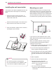
ASSEMBLING AND PREPARING Adjusting the angle English ENG 1 Place the monitor mounted on the stand base in an upright position. 2 Adjust the angle of the screen. The angle of the screen can be adjusted up to 5° forwards and 15° backwards for a comfortable viewing experience. 15 Rear Side -5 Using the Kensington locking device The connector for the Kensington lock is located on the rear of the monitor.
ASSEMBLING AND PREPARING Swivel stand 3 Be careful with the cables when rotating the screen. ENG English Image shown may differ from your Monitor yy set. 1 Swivel 90 degrees and adjust the angle of the Monitor set to suit your view. Using the Pivot function The pivot function allows you to rotate the screen 90 degrees clockwise. 1 Lift the monitor to its highest height to utilize the Pivot function. 2 Landscape & Portrait : You can rotate the panel 90o clockwise.
ASSEMBLING AND PREPARING English ENG Installing the wall mount plate Mounting on a wall This monitor has a VESA compatible mount on the back. Most mounts will require an LG mounting plate. Install the monitor at least 10 cm away from the wall and leave about 10 cm of space at each side of the monitor to ensure sufficient ventilation. Detailed installation instructions can be obtained from your local retail store. Please refer to the manual to install and set up a tilting wall mounting bracket.
ASSEMBLING AND PREPARING Model 11 23CAV42K CAUTION Unplug the power cord before moving or inyy stalling the monitor to avoid electric shocks. Installing the monitor on the ceiling or on a yy slanted wall may result in the monitor falling off, which could lead to injury. Please use a LG wall mounting bracket when using a VESA mount. For more information, contact your local retail store or a qualified installer. Applying excessive force when fastening yy screws may cause damage to the monitor.
USING THE MONITOR SET USING THE MONITOR SET English ENG D-SUB IN connection - PC This monitor supports the *Plug and Play yy feature. *Plug and Play: A feature that allows you to add a device to your computer, without having to reconfigure anything or install any manual drivers. Connecting Input Signal Cable Self Image Adjustment Press the power button on the front to turn on the monitor.
USING THE MONITOR SET 13 DVI connection LAN connection Transfers digital video signals from the Cloud Monitor to an extended monitor. Connect the Cloud Monitor to an extended monitor using a DVI cable. Connect the router or switch to the monitor using a LAN cable as illustrated below. DVI-I(D) IN LAN Hub/Router NOTE The LAN cable is sold separately. yy The following LAN cable type can be used: yy Standard: IEEE 802.
USING THE MONITOR SET Peripheral device connection English ENG Connect peripheral devices to the monitor using USB, microphone and headphone ports. NOTE Peripheral devices are sold separately. yy The USB ports on the left and bottom of the yy monitor can be used to connect the keyboard, mouse, and other USB devices. Cables with angled plugs may have clearyy ance issues, use straight plugs when possible.
CUSTOMIZING SETTINGS 15 CUSTOMIZING SETTINGS ENG English Accessing The Main Menus 1 Press any button on the front of the monitor to display the MONITOR SETUP OSD menu. 2 Press to select the desired menu item. 3 To change the settings of the selected item press the buttons on the front of the monitor. To return to the upper menu or set other menu items, use the up arrow ( ) button. 4 Select EXIT to leave the OSD menu.
CUSTOMIZING SETTINGS Customizing Settings English ENG Menu Settings 1 Press MENU button on the bottom of the Monitor set to display the MENU OSD. 2 Set the options by pressing the ◄ or ► or ▼ buttons. 3 Select the "NEXT MENU" button to enter the more option settings. 4 Select EXIT to leave the OSD menu. To return to the upper menu or set other menu items, use the up arrow ( ) button. VOLUME Each option is explained below.
CUSTOMIZING SETTINGS 17 PICTURE ENG English 1 Press MENU button on the bottom of the Monitor set to display the MENU OSD. 2 Select the "NEXT MENU" button to enter the more option settings. 3 Enter to PICTURE by pressing the ▼ button. 4 Set the options by pressing the ◄ or ► or ▼ buttons. 5 Select EXIT to leave the OSD menu. To return to the upper menu or set other menu items, use the up arrow ( ) button. Each option is explained below.
CUSTOMIZING SETTINGS COLOR English ENG 1 Press MENU button on the bottom of the Monitor set to display the MENU OSD. 2 Select the "NEXT MENU" button to enter the more option settings. 3 Select COLOR by pressing the ► button. 4 Enter to COLOR by pressing the ▼ button. 5 Set the options by pressing the ◄ or ► or ▼ buttons. 6 Select EXIT to leave the OSD menu. To return to the upper menu or set other menu items, use the up arrow ( ) button. Each option is explained below.
CUSTOMIZING SETTINGS 19 DISPLAY ENG English 1 Press MENU button on the bottom of the Monitor set to display the MENU OSD. 2 Select the "NEXT MENU" button to enter the more option settings. 3 Select DISPLAY by pressing the ► button. 4 Enter to DISPLAY by pressing the ▼ button. 5 Set the options by pressing the ◄ or ► or ▼ buttons. 6 Select EXIT to leave the OSD menu. To return to the upper menu or set other menu items, use the up arrow ( ) button. Only available in D-SUB input mode.
CUSTOMIZING SETTINGS OTHERS English ENG 1 Press MENU button on the bottom of the Monitor set to display the MENU OSD. 2 Select the "NEXT MENU" button to enter the more option settings. 3 Select OTHERS by pressing the ► button. 4 Enter to OTHERS by pressing the ▼ button. 5 Set the options by pressing the ◄ or ► or ▼ buttons. 6 Select EXIT to leave the OSD menu. To return to the upper menu or set other menu items, use the up arrow ( ) button. Each option is explained below.
CUSTOMIZING SETTINGS 21 Volume ENG English 1 Press the VOL button at the bottom of the monitor to display the VOL OSD menu. 2 Press the◄ or ► button to adjust the volume. 3 Press the VOLUME button to enable or disable Mute. 4 Select EXIT to leave the OSD menu. Each option is explained below. MENU > NEXT MENU > VOLUME VOLUME Description Adjusts the volume (only available in CLOUD input mode).
Troubleshooting TROUBLESHOOTING English ENG Nothing is displayed on the screen Is the monitor's power cord plugged in? yy Check if the power cord is correctly plugged in to the outlet. Is the power indicator on? yy Check the power indicator. Is the power indicator displaying as white? yy Adjust the brightness and the contrast. Is the power indicator blinking? yy If the monitor is in power saving mode, move the mouse or press any key on the keyboard to switch the display on.
Troubleshooting 23 The image is displayed abnormally. Pressing the AUTO button will automatically optimize the screen to the current display mode. Does the screen exhibit vertical lines? Pressing the AUTO button will automatically optimize the screen to the current display mode. Does the screen display horizontal Pressing the AUTO button will automatically optimize the screen to the current frequencies, or does the text appear display mode.
Specifications PRODUCT SPECIFICATION English ENG LCD Screen Type Resolution Pixel Pitch Maximum Resolution Video Signal Input Connector Power Dimension/ Weight Weight (Without Packaging) AC/DC Adapter Stand Angle Adjustment Environment Condition Recommended Resolution DVI-I output Horizontal Frequency Vertical Frequency Synchronization 15-pin D-SUB (Analog) 19 V 2.3 A Power Consumption(Typ.) (D-sub/CLOUD) 58.
Product Specification 25 Preset Mode Horizontal Frequency (kHz) Vertical Frequency (Hz) Polarity (H/V) 720 x 400 31.468 70.08 -/+ 640 x 480 31.469 59.94 -/- 800 x 600 37.879 60.317 +/+ 1024 x 768 48.363 60 -/- 1280 x 1024 63.981 60.02 +/+ 1680 x 1050 65.290 59.954 -/+ 1920 x 1080 67.
Proper Posture PROPER POSTURE English ENG Proper posture for using the monitor Adjust the angle so that the screen is slightly lower than your eyes. Using the monitor for a prolonged period of time can cause eye fatigue. Take a 10-minute break every yy hour. The stand is designed to best support the monitor when the optimal conditions are selected. yy Adjust the angle of the monitor from -5° to 15° to obtain the best view of the screen. You should be looking slightly down at the screen.
Using CLOUD Solution 27 USING CLOUD SOLUTION ENG English NOTE yyMenus and functions in CLOUD mode may be slightly different depending on the firmware version. You can download the user manual for each version from the Teradici homepage: http://www.teradici.com yyTo check the firmware version, see page . Connect Screen The Connect screen is shown during start-up, except when the portal has been configured for a managed start-up or auto-reconnect.
Using CLOUD Solution English ENG If you select the Connect button, the connection session is started. When the connection is pending, the "Discovering hosts, please wait…" message is displayed on the OSD local GUI. When the connection is established, the OSD local GUI will disappear and be replaced by the session image. Configuration Window In the Configuration window, the administrator can access the window tabs that contain the settings to configure and manage the portal environment.
Using CLOUD Solution NOTE The Network parameters can also be conyy figured using the Webpage Administration Interface. yy Gateway The Gateway field contains the gateway IP address of the device. If DHCP is disabled, this field is required. If DHCP is enabled, this field cannot be edited. yy Primary DNS Server The Primary DNS Server field contains the primary DNS IP address of the device. This field is optional. If DHCP is enabled, this field cannot be edited.
Using CLOUD Solution English ENG Tab The IPv6 tab is used when the portal is connected to the network configured with the IP v6. yy Secondary DNS Server The Secondary DNS Server field contains the secondary DNS IP address of the device. This field is optional. If DHCPv6 is enabled, this field cannot be edited. yy Domain Name The Domain Name field contains the domain name used, e.g. "domain local". This field is optional. It specifies on which domain the host or portal operates.
Using CLOUD Solution NOTE The portal label parameters can also be conyy figured using the Webpage Administration Interface. Discovery Tab The Discovery configuration tab allows the administrator to easily find a portal in the PCoIP system. The Discovery parameters can also be configured using the Webpage Administration Interface. NOTE The Discovery parameters can also be conyy figured using the Webpage Administration Interface.
Using CLOUD Solution English ENG Session Tab The Session tab allows the administrator to set the method to connect the device to a peer device. See below for information how to set for each option. NOTE The Session parameters can also be conyy figured using the Webpage Administration Interface. yy Connection Type The Connection Type field allows the user to select the device to be connected with the portal.
Using CLOUD Solution 33 yy Enable Auto-Reconnect If this option is selected, reconnection is attempted automatically when a session is disconnected or the user is logged off. NOTE This setting is provided only for the client. yy yy Enable Peer Loss Overlay The "Connection Lost" message is displayed. The display is the same as in the VDI environment. The default is Disable. NOTE This setting is provided only for the client.
Using CLOUD Solution English ENG yy View Connection Server In the Session tab, you can select to enable the user client to access the VMware View Connection Server. To do this, select View Connection Server for Connection Type. yy Enable Auto-Reconnect If this option is selected, reconnection is attempted automatically when a session is disconnected or the user is logged off. NOTE This setting is provided only for the client.
Using CLOUD Solution 35 NOTE This setting is provided only when a smart yy card is used. yy Desktop Name to Select Enter the name of the pool/desktop which the user client uses upon starting a session. yy Port For the default setting, leave the port field empty. When the VMware View Connection Server uses the SSL authentication, enter 443 in the Port field.
Using CLOUD Solution English ENG yy View Connection Server with Auto-Logon In the Session tab, you can select to enable the user client to automatically access the VMware View Connection Server. To do this, select View Connection Server with Auto-Logon for Connection Type.
Using CLOUD Solution NOTE This setting is provided only when a smart yy card is used. yy View Connection Server + Kiosk Select View Connection Server + Kiosk to use the kiosk mode. You can configure the View Connection Server + Kiosk mode using the Webpage Administration Interface. NOTE You cannot use the kiosk mode by connectyy ing to the host PC.
Using CLOUD Solution English ENG yy Enable Preparing Desktop Overlay If this option is selected, the "Preparing Desktop" message is displayed on the screen when the user is logged in. yy Disconnect Message Filter This option determines the type of message to display when a session is disconnected. - Show All: Shows all the error messages. - Show Error and Warning Only: Shows the error and warning messages only. - Show Error Only: Shows the error messages only. - Show None: Shows nothing.
Using CLOUD Solution 39 yy Remember Username If this option is selected, the username which is previously used to access the VMware View Connection Server is automatically entered in the username field. yy Use OSD logo for View banner If this option is enabled, you can change the OSD logo of PCoIP during the login.
Using CLOUD Solution English ENG Language Tab The Language tab allows the administrator to set the OSD language. NOTE The Language parameters can also be conyy figured using the Webpage Administration Interface. yy Enable Peer Loss Overlay If this option is selected, the "Network Connection Lost" message is displayed on the screen when it is confirmed that the network is disconnected.
Using CLOUD Solution NOTE Display Tab The Display tab allows the user to configure the EDID function of the monitor. NOTE The OSD parameters can also be configured yy using the Webpage Administration Interface. yyThe Enable display override function can be used when the EDID function of the monitor is not running.
Using CLOUD Solution English ENG Reset Tab The Reset tab allows the administrator to reset all configurable parameters stored in Flash. NOTE yyThe Reset function can also be accessed through the Webpage Administration Interface. Diagnostics Window In the Diagnostics window, the administrator can access the window tab to diagnose the portal. The Diagnostics window has the following tabs: yy Event Log yy Session Statistics yy PCoIP Processor yy Ping Each tab has the Close button to close the window.
Using CLOUD Solution yy PCoIP Processor Tab The PCoIP Processor tab allows the administrator to view the portal PCoIP processor's uptime since its last booting. NOTE yyThe PCoIP Processor Uptime can also be viewed using the Webpage Administration Interface. yy PCoIP Packets Sent The PCoIP Packets Sent field shows the total number of PCoIP packets sent from the portal to the host in the last active session.
Using CLOUD Solution English ENG yy Ping Tab The Ping tab allows the administrator to perform a ping test to the device and check if it can reach the overall IP network. This is useful to check whether the device can reach the host. NOTE yyThe Ping tab has no corresponding menu in to the Webpage Administration Interface of Section 1. Information Window In the Information window, the administrator can access the Version tab that contains the device related information.
Using CLOUD Solution yy VMware View Tab The VMware View tab allows user to specify the client behavior for when a user cannot check the secure connection to a server. yy Mouse Tab The Mouse tab allows the user to modify the OSD and RDP session's mouse cursor speed setting. NOTE yyThe OSD mouse cursor speed setting does not affect the mouse cursor settings when a PColP session is active unless the Local Keyboard Host Driver function is being used. (see PColP Host Software User Guide for more information).
Using CLOUD Solution English ENG yy Keyboard Tab The Keyboard tab allows the user to modify the OSD and RDP session's keyboard repeat setting. NOTE yyThe OSD keyboard setting does not affect the keyboard settings when a PColP session is active unless the Local Keyboard Host Driver function is being used. (see PColP Host Software User Guide for more information). yyThe Keyboard tab has no corresponding menu in the Webpage Administration Interface of Section 1.
Using CLOUD Solution yy Touch Screen Tab The Touch Screen tab allows the user to specify the touch sensitivity and alignment when the monitor supports the touch screen function. NOTE yyIt is applicable when the VMware View Connection Server version is 4.5 or later. yy Enable Configuration When this option is selected, you can set the display position and alignment.
Make sure to read the Safety Precautions before using the product. Keep the Owner's Manual(CD) in an accessible place for future reference. The model and serial number of the SET is located on the back and one side of the SET. Record it below should you ever need service.